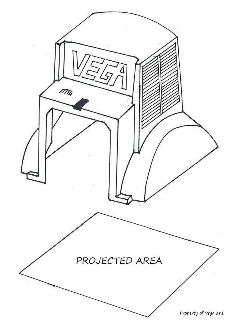
1) Projected Area of Molded Part
The real surface of the molded part is the area in contact with the molten plastic. Naturally the Plastic Part has a complex design, and obviously the pressure will act perpendicularly to each bit of surface element. The force we are interested in, is only the part acting along the cylinder rod. The other forces acting on the part and resulting from the injection pressure, concern the mold designer and maker. Therefore, if you project the surface of the part (only the one related to the cylinder) on a plane perpendicular to the cylinder rod, you get the projected surface we are interested in. Of course, in this analysis we consider the cylinder directly connected to the part, without wedges or similar.
Most CAD and CAM software are perfectly capable to make this calculation within a few mouse clicks.
To obtain the force necessary to withstand the plastic pressure and therefore to know the proper size of the piston of our hydraulic cylinder, we then need to know the projected surface.
We can suggest choosing the bore size of our Hydraulic Cylinder so that it exceeds the cavity pressure force by 1.5 times, to ensure a proper safety factor. For example, if expected cavity pressure was 600 bar and the projected surface area of the component was 10 cm square, we know that there would be 60’000 Newton of force acting on the component (600 bars = 6000 N/sqcm * 10 cm square). If we multiply 60’000 Newton by 1.5 ratio, we find that we need approximately 90’000 Newton of force to counteract the cavity pressure (i.e. 9000 daN).
Statistically the maximum average Oil Pressure coming from the Hydraulic Pump of a Plastic Injection Machine is 130 to 140 bars.
In order to counteract the force of 90’000 N we need to select a bore diameter of 100 mm.
At this point there are 3 options while choosing a Vega cylinder: the first is to buy a normal cylinder with 100 mm of bore diameter such as V210CR or V450CM, the second is to reduce the size of our cylinder to 80 mm and use a Check Valve, the third choice is to buy an hydraulic locking cylinder such V260CF.
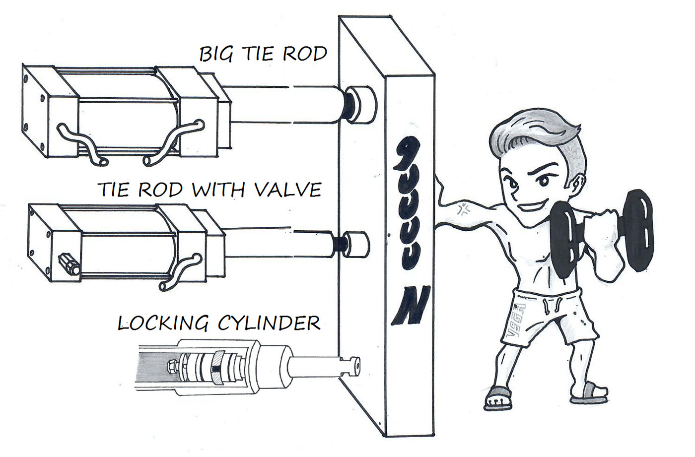
Let us now review the last 2 options as follows.
An hydraulic cylinder with bore diameter of 80 mm at the pressure of 130 bars is able to withstand a force of approx. 65000 N.
What is a Check Valve? And why could it be useful?
Check valves or non-return valves are mechanical valves that let the oil flow in only one direction, avoiding flow reversal. They are classified as one-way directional valves. Fluid flowing in the desired direction opens the valve, while a backflow forces the valve closed.
By using this valve we create a hydraulic lock inside our cylinder.
What is the limit? And advantages?
If we are not careful the pressure inside our hydraulic cylinder can increase so much as to damage its static seals, the o-rings or even the cylinder structure itself. (Each cylinder produced by Vega has a maximum oil pressure limit, e.g. each cylinder has a name like V450CM and that means 450 is the maximum pressure for that cylinder in bars.)
If, for example, we select a cylinder dia. 80, in the case just mentioned, pressure will go up 180bars, which implies an increase of 50 bars as to the nominal one. The cylinder will not suffer, but due to oil compressibility, with a stroke 100, the rod end will come back some 0.3 mm and even worse with smaller diameters.
So, the 3 advantages in using this solution are: (1) the Hydraulic Pump can be switched off once the cylinder is in position, (2) the overall size of the cylinder can be reduced, (3) a reduction of costs of both our cylinder and mold.
The main drawback is that the piston rod may bounce back due to oil compression.
The third option we mentioned before was to use a Hydraulic Locking Cylinder.
In this case a V260CF cylinder with a bore size of 36 mm could be more than enough to withhold the force generated by the mold part.
What is the difference in using a Locking Cylinder compared to a Check Valve?
The main difference is that inside a Locking Cylinder the oil pressure does not increase because the force generated by the injection is supported by a Hardened Steel Ring.
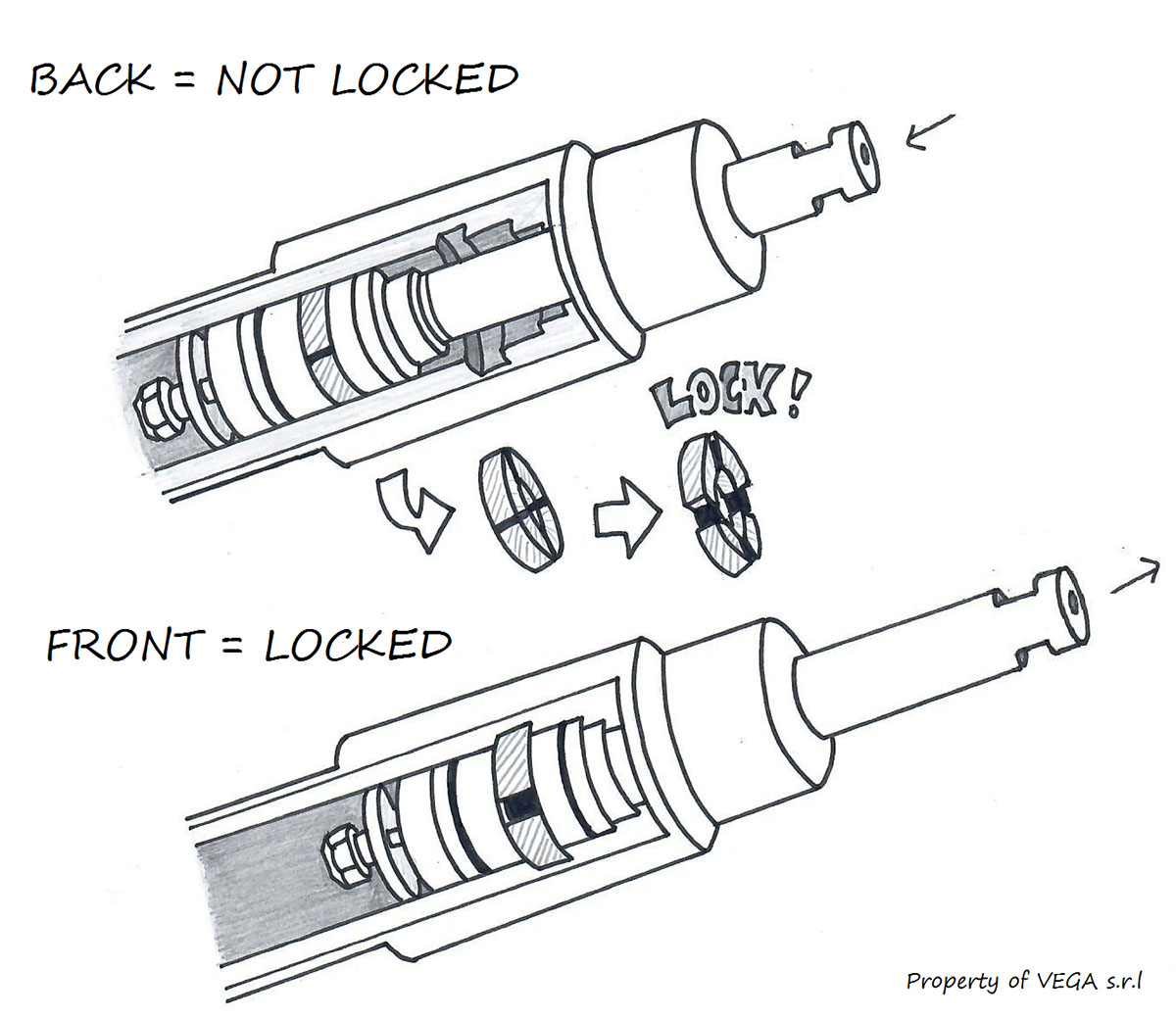
A second difference lies in the precision we get by using a mechanical lock instead of relying on oil pressure. As seen above, even with bore 80, the rod end would bounce back some 0.3 mm, which the V260 rod will not do.
To get more insight on this please read this post: OTHER WAYS TO ACTUATE MOLD CORES PULLS AND SLIDES.