written by Stefano Rogora (Technical Support Manager) and Alessandro Draganti (Technical Director)
Yes, it’s true: switches are necessary, but there are so many types and versions that they seem to make a “jungle” out there, and it’s likely to get lost in it.
For that, some basic ideas are required, in order to make a choice effective and satisfactory.
In a few words, a switch lets you know where a part of the machine is. It is necessary if you have a cycle and you require that a sequence is made in the right order and at the right moment. Just think of a complex mold with the two plates on the press, and a lot of cores. If just one of them is actuated after the press opens, then just a disaster will happen: breakages, machine downtime, loss of production and money, penalties, and more.
This nightmare can be avoided basically in two ways: timing each movement, or using switches.
Timing allows enough time (and a little more) for completing the operation safely. Anyway, is something sticks on the way, nobody knows, and the disaster is back again…
A switch lets you know the position of an item, so you are sure it is right there, and disaster will hopefully fade away forever.
So we must enter this “jungle”, because it’s the only way to stay safe. This is not to imply that switches are perfect, so there are some subject to take care of, in order to be safe and happy.
There are two ways of using switches in molds: directly on its components or on the cylinders. We’ll here consider only this latter subject.
The main subjects dealt-with in this article, will then be:
1) Main types of limit-switches.
2) Other transducers used for cylinders in molds.
3) Troubleshooting and making one’s life much easier with Vega Switch Connection Box.
Let’s have a quick look at each of them.
1) Main types of limit switches
Just the following list is a true jungle… Let’s now go by order.
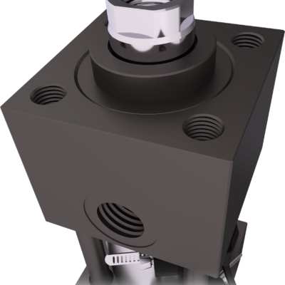
Mechanical switches
Electrical contact is opened or closed by mechanical parts commanding it at the right moment. Their variety and capacity is almost limitless. Luckily, only a few types are used in cylinders for molds. Some are custom-made as for Vega V450.
Magnetic switches
They operate detecting a magnetic field, generated by a permanent magnet placed nearby.
They are widely used in industrial automation (molds for plastics and injection die casting, machine tools and so on), actuated by cylinders (hydraulic, pneumatic or electric).
The sensor sends an electrical signal to the control equipment, as soon as the cylinder completed its motion (stroke).
There are various types, among which the most common are the REED, the Hall effect electronic types, PNP and NPN.
For a correct application it is necessary to avoid all kind of strong electromagnetic interference (motors, contactors, power lines, magnetic chucks for molds or else). Of course all masses of ferromagnetic material with a residual magnetic field should be avoided.
For correct installation and operation, minimum distance from the sensor and the ferromagnetic masses should be at least 25 – 30 mm. Anyway, the application should consider all aspects, especially the cons.
If these latter appear to be too many, it’s advisable to evaluate another sensor type (mechanical or inductive) more suitable to the operative conditions.
By the way, Vega was the first Company to install magnetic switches on a hydraulic cylinder.
Pros: Simple and affordable. Easy to use.
Cons: Possible interference with other magnetic fields may limit their use.
Reed type magnetic switches
The Reed sensor has a normally open (NO) couple of foils made of ferromagnetic material. When placed in a magnetic field (which must be strong enough), their ends get opposite polarity, stick together and close the contact. The foils are placed in a glass tube filled with an inert gas such as nitrogen or argon, so called a “Reed ampoule“.
The operating range is between 0 and 230 VAC, max. temperature 80°C, protection IP 66 to 67 (according to manufacturer). Max current for resistive load may be from 500 to 800 mA.
Pros: Simple and affordable. Easy to use. No need for permanent power supply (only 2 wires required).
Very cheap.
Cons: Risk of double signal in certain specific situations.
The limited current prevents from directly controlling a relay.
Chance of hysteresis, with a reading range up to 12-15 mm, which is too much for short cylinder strokes.
If series connected and equipped with signaling LED, there is a voltage drop with consequent increase in current and reduced life-span of the switch. Better not connecting more than 4 of them in series.
“Electronic” type magnetic switches
The “Hall effect” electronic sensors are widely used in process control, and can be PNP (positive + output signal) or NPN (negative output signal, 0V).
Unlike the REEDs, this sensor requires a DC stabilized power supply (max 30V).
3 wires for connection: 2 for power supply ( +24VDC e 0V) and one for output ( PNP or NPN). The most used are PNP type for easily matching the PLC on board the m/c.
Max. temperature 80°C, protection IP 66 to 67 (according to manufacturer). Max current for resistive load no more than 200 mA.
Pros: Long electrical life.
High commutation frequency (over 1 KHz, while a normal REED stops at 200).
Very low hysteresis value, so not prone to double signals, even if used on short cylinder strokes of 20 – 25 mm.
Protection circuits are standard, so preventing damages from connection errors or short-circuits.
Cons: They need a permanent power supply.
The limited current prevents from controlling directly a relay.
They are not as compact as the REEDs ones.
Vega developed magnetic sensors MSU1/4(one relay) and MSU2/3 (two relays), with a power supply circuit and a clean contact 0V relay-controlled.
They can be configured as PNP or NPN, and can be connected to any type of press (old or new) provided that a 24VDC power supply is used when the press hasn’t it.
In this latter case, voltage supply to sensors in the press can be 24 – 48 – 110 VAC. So, in these m/c only mechanical or REED sensors are installed, with all the Cons we already saw.
With Vega sensors mentioned above, all these problems disappear.
Inductive switches
Inductive type sensors are the most used ones in industrial automation. Their working principle is based on a change in inductance due to the presence of a metallic object within the sensor action field. The sensor generates a high-frequency electromagnetic field and, when a metallic object approaches, such fields weakens proportionally to the approach of the said object. Above a given value, the output signal is commuted. As trigging frequency can reach some KHz, these sensors can detect objects at high speed.
They need continuous power supply, max 30V stabilized DC, and of course 3 wires (2 for power – +24VDC and 0V) and one for output signal (PNP, for most PLC on board of the machines, or NPN). Typically they are stainless steel round threaded type, IP67 operating max at 70°C or (for some models) 120.
Compared to the mechanical switches. Pros and Cons are:
Pros: Long electrical life.
Contactless, even at very high trigging frequency.
Excellent precision and repeatability.
Non affected by vibrations, dust and humidity.
Protection circuits are standard, so preventing damages from connection errors or short-circuits.
Cons: They need a permanent power supply.
The limited current prevents from controlling directly a relay.
Capacitive switches
They are electronic transducers which give an output signal when a material enters their active zone, even if there is no physical contact.
The difference with the inductive sensor and with the “Hall” effect ones, is that their operation is not limited to ferromagnetic materials. Capacitive sensors can (with different degrees of sensitiveness) detect all solid and liquid materials (wood, plastic, granular products and so on). The working principle is based on a variation of capacity, generated by a surface which approaches the active part of the sensor.
They need continuous power supply, max 30V stabilized DC, and of course 3 wires (2 for power – +24VDC and 0V) and one for output signal (PNP, for most PLC on board of the machines, or NPN). Typically they are stainless steel round threaded type, IP67 operating max at 70°C or (for some models) 120.
Compared to the mechanical switches. Pros and Cons are:
Pros: Long electrical life.
contactless, even at very high trigging frequency.
excellent precision and repeatability.
non affected by vibrations, dust and humidity.
Protection circuits are standard, so preventing damages from connection errors or short-circuits.
Cons: They need a permanent power supply.
The limited current prevents from controlling directly a relay.
2) Other transducers used for cylinders in molds
Linear transducers
Linear displacement transducers are widely used in many applications where it is necessary to have full control on the movement / displacement of an object driven by actuators / cylinders (hydraulic or pneumatic).
They convert an input physical dimension (e.g. a linear displacement) into an analog output electrical signal (voltage, 0 to 10, or current 4 to 20mA). They also can directly give a digital output to the m/c PLC (CNC or injection press).
Such a transducer lets you set with high precision and repeatability the displacement of the actuator / cylinder.
In the molds they can be used on cylinders for dual-material injection or for two-stage unscrewing devices.
Pros and Cons of the Linear displacement transducers as to ON/OFF magnetic sensors.
Pros: This kind of transducer, duly interfaced with the injection press PLC, and using a proportional valve, can control all motion parameters (displacement, speed and acceleration), also allowing a stop at an intermediate spot, chosen at wish.
excellent precision and repeatability.
Protection circuits are standard, so preventing damages from connection errors or short-circuits.
Cons: They need a permanent power supply.
Installation and transducer itself are costlier than simpler solutions.
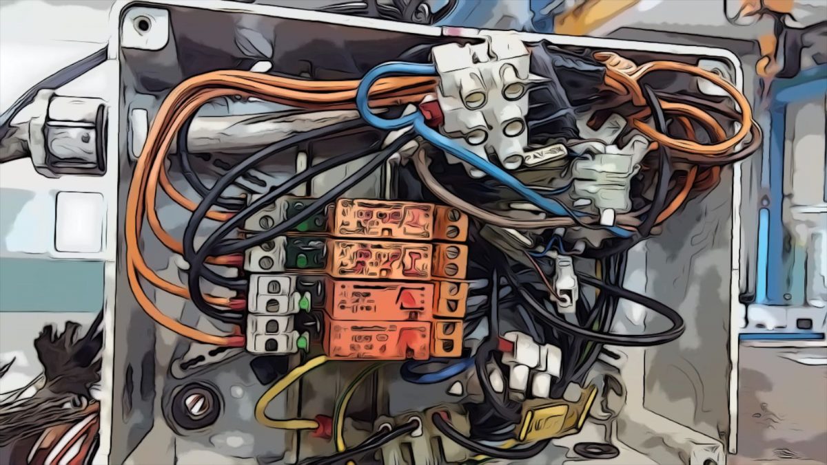
3) Troubleshooting and making one’s life much easier with Vega Switch Connection Box
Sensors connection in series
A series connection for a number of sensors (of course not possible for linear transducers), is used as a safety system for controlling some actuators (hydraulic, pneumatic or electric cylinders), which must move simultaneously in a single sequence or production phase.
Doing so, all the “switches” must be closed in order to let currant pass, so moving to the next step of the production cycle. If just one sensor fails, the circuit keeps open and next operation cannot be performed. When everything is stopped, no harm or damage can happen…
It may look strange, but a very important thing to take care of is, in this case, voltage drop. This happens more frequently (for both REED and electronic) sensors, when signaling LEDs are present.
As an average, voltage drop for each sensor with LED is about 0.8 – 1 V, so that total drop will be this values times the No of sensor in series. If they are 4, total average drop will be close to 4 V, which leads to a mere 20 VDC usable, instead of the nominal 24.
For this reason, it’s advisable not to connect in series more than 4 sensors, also checking (on the datasheet) their operating range and admissible load.
Cable length for each sensor should not exceed 3 to 4 meters, because the consequent voltage drop could be too high, so increasing the current in the circuit.
This kind of connection is reasonable, but in some extreme situations it could not be safe enough.
Let’s, make an example:
A mold with 4 tables, each one driven by a cylinder.
Total No of cylinders: 4.
Total No of switches: 8 (2 on each cylinder).
Total No of series connections: 2 (one ahead with 4 switches, 1 back with 4 switches).
Let’s imagine that one of the contacts (problem often present with REED switches if the current is too much), sticks (of course in the closed position). For the series circuit, the cylinder corresponding to the stuck contact, is always in the “end of stroke” position. So, if by chance it is still moving while the other 3 cylinders already reached their final position, the circuit closes and the PLC moves to the next step, while one cylinder is still moving! You may imagine what can happen, how many inconveniences, breakage(s) and loss of time…
It is true that the PLC on the press, if duly configured, can stop the productive cycle if two conflicting signals appear at the same time, but this is just one aspect of the issue: the other one is finding the defective sensor…
For this reason, Vega developed the SIM08, a device for controlling and handling the signals. In fact, it can check how every single sensor works. In addition, wiring is very easy and simple, because connectors and LEDs are used everywhere. No more mess with tangling wires and the long troubleshooting for finding the guilty sensor!
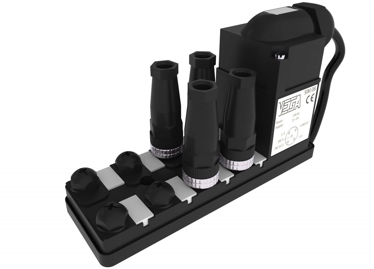
Dip-switches let you choose and define the sensors actually used (No and type).
Electrical connections to the press are :
Two power supply wires ( +24VDC – 0V),
Two clean contacts NO, 0V, one for actuators in, the other for actuators out, and
A safety NC clean contact.
Protection degree: IP67, operating temperature: 0 – 45°C
If the SIM08 detects two signals at the same time, it stops the cycle being performed, and the NC contact switches to open. If it is connected to the PLC of the press (or to a secondary relay circuit), it can operate a visual or audible warning device.
Pros: Dramatically simplifies connections.
Guarantees the best safety level for your mold.
Protection circuits are standard, so preventing damages from connection errors or short-circuits.
Cons: It needs a permanent power supply.
Conflict of interest between mold maker and mold user: why should the former pay an extra amount for a device useful only to the latter?
Conclusion:
For not getting lost in the ‘jungle’ of sensors, you need two things:
A map of the jungle (precise knowledge of what sensors give you and what you need from them, as we tried to give you that in this article), and: A good ‘machete’ like Vega SIM 08.
We can compare Vega SIM 08 to a sharp and duly shaped machete, which simplifies the overall efficiency and cost of a mold. We strongly recommend that you take a look at it before taking a decision regarding sensors…