by Alessandro Draganti, Technical Director Vega srl.
Threads in Molds
Except in the most simple of cases, molds require moving parts. One specific situation is the production of threaded finished pieces.
Such pieces can be entirely threaded – like in the case of a bottle cap – or partially – a fitting, or a more complex part having a thread in it. Also, the requested precision may vary a lot from case to case. Due to that, the solutions adopted for disengaging the piece from the mold vary accordingly.
Such solutions are basically divided into two main groups:
• Collapsible devices
• Rotating devices
We’ll quickly consider the first and then examine the second one a bit more in detail.
Collapsible devices
The operating mode is very clear. There is no need of unscrewing the part. In fact, the inside of the collapsible device slides backwards, and lets the threaded core free to collapse.
Of course, in order to do so, the thread must not be continuous along the circumference, but it must have some slots to allow it to collapse. Their number and width depend on thread depth. The result on the finished part (which is generally a bottle cap) is an ‘interrupted’ thread. This has no drawback in such applications.
Pros:
– Cost; many units can be installed in a single mold.
– A lot of manufacturers; choice option is wide. Cons:
– An interrupted thread is no problem for bottle caps, but it is for other types of folded parts.
- With some models, many slide movements are required. The simplest collapsible devices just require one movement for collapsible closure, and one for ejection, which should be acceptable in most cases.
Where more demanding performances are required, then a continuous thread should be adopted and the part has to be unscrewed from its core. Different solutions come to mind…
Rotating devices
Rotating devices can be very different one from the other. The main families are:
• Electric motors / gear motors
• Hydraulic motors
• Rack hydraulic cylinders for rack/pinion systems
Let’s have a look at them in more detail. The first two groups use a rotating shaft to actuate the core, either directly or through gears (or a train of them). The third one will be explained later.
Electric Motors / Gear Motors
The main properties of an electric system are well known. Typically, an electric motor is rather fast but its torque is not on the highest side. New servo-motors (especially for short periods) partly overcome the lack of torque.
The simple control of an electric motor is easy and cheap, while a sophisticated drive can be costly. It has the advantage of precisely controlling position, speed and acceleration, being good for fast cycles where the required torque is not too high. Of course, a very precise position for the end-of-stroke implies a very precise control, which may increase the cost. An alternative is the use of mechanical (and adjustable) stops for the end-of-stroke. With a drive, the end-of-stroke speed will be low and the parts will not hit each other hard.
For multiple cores, a train of gears is required, or a pulley/belt system as in the last picture. Normally this does not allow for very high torques.
This system is fairly compact and can fit in tight spaces, but the electric motor must be kept away from areas having a very high temperature. This is especially true when belts are used. The electrical connections are often on the side, and this may be inconvenient in some type of molds.
This is clearly the most natural solution in electric presses.
Hydraulic Motors
In many ways, these devices are similar to electric motors, with the exception that the driving ‘agent’ is a fluid and not electricity, so their use on hydraulic presses comes natural.
Basically, they have the same pros and cons of electric motors. They are usually rather fast, and torque is generally higher than electric motors. They are normally slower than electric motors, and they often don’t require a gear reducer. If a precise end-of- stroke position is required, a proportional valve has to be used, together with some detection system. All that adds to the cost, especially if we include mechanical stops.
As for electric motors, a train of gears is required in the case of multiple cores; the system is rather compact but oil connections are often on the side, therefore increasing overall dimensions. Operative temperatures are the same as those of normal hydraulic cylinders.
Some manufacturers sell ready-to-use units.
Rack Hydraulic Cylinders, for Rack/Pinion Systems
In this case, the base motion is linear, and not a rotation. By moving back and forth, the rack engages a gear or a train of gears, which then rotate the core. It seems more complex, but this allows for high unscrewing torques.
This category can be divided into two branches:
• DIY (do-it-yourself) systems
• Compact systems, supplied as a readily installable unit
It seems that many mold makers stick to the first solution, but we believe it’s good to examine all the different aspects to make the best possible choice.
 DIY Systems
Basically, the customer takes a normal tie rod cylinder, a rack and its guide, then puts everything together by linking the rod to the rack.
Pros:
– Almost all the parts are readily available from the market.
– Multiple pinions may engage on the rack and this may lead to a saving in the gear train.
– Their stroke is defined by the cylinder length, so there is generally no need for sophisticated controls.
If the cylinder is cushioned, a soft end-of-stroke is attained automatically.
Cons:
– Very cumbersome system.
– Oil ports are generally on the side, but this is not so crucial as the cylinder is usually outside.
– Often, only one rack is used: this once again turns against compactness. In fact, two-rack solutions are even larger.
Because of its large dimensions, this system is used where space is not a concern. It may perform well, provided that all the parts are finely machined and assembled.
Compact systems supplied as a readily installable unit
They are generally customized (starting from the manufacturer’s standard parts), meaning that the customer tells the manufacturer what kind of unit he wants, and the supplier gives it as per the customer’s request.
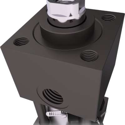
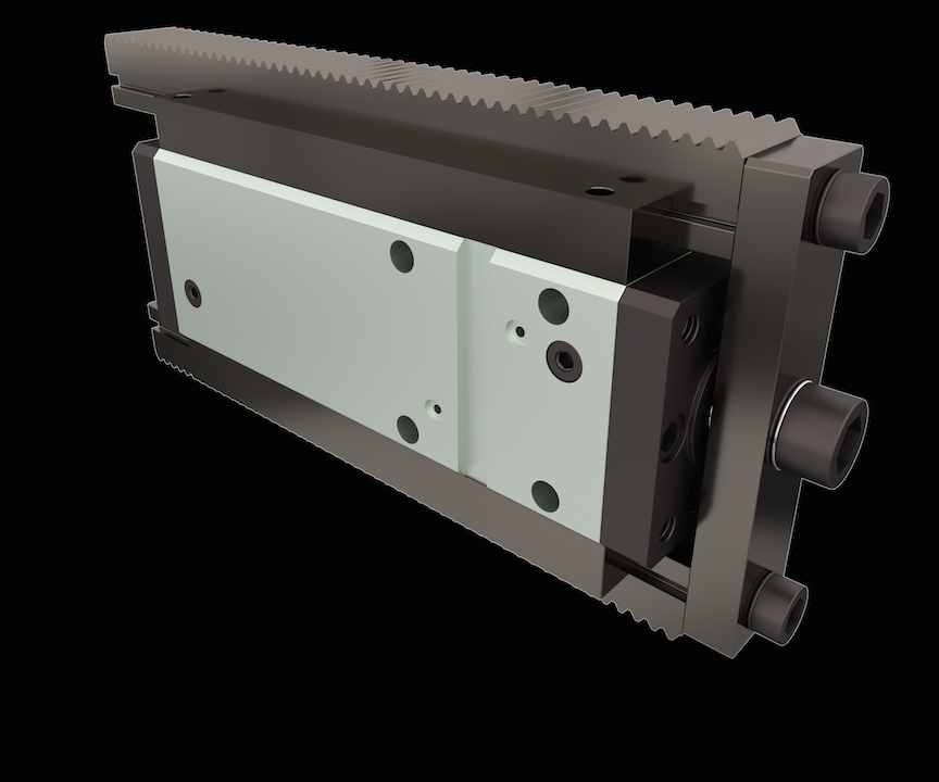
One of the most appreciated solutions in this area is the V210 CS made by Vega.
Pros:
– The units come practically ready to assemble.
– It is the most compact solution when using a rack.
– Multiple pinions may engage on the rack and this may lead to a saving in the gear train.
– Double racks can be easily installed for saving space in complex situations.
– Their stroke is defined by the cylinder length, so there is usually no need for sophisticated controls.
– Manifold oil supply can be adopted, and the cylinder can be placed almost inside the mold. This is really space-saving.
– A fine tuning for the rear position can be adopted, as well as switches for detecting rod (and rack) end positions.
Cons (more or less):
– Customers may thing that price is the biggest concern. This is not necessarily true. If we consider just the purchase price, then this solution is likely more expensive than purchasing the single components; but the latter have to be assembled and often machined, in addition to the designing required. The final cost for the customer depends on a lot of factors, which have to be carefully considered, and might be more than the compact, ready-to-use systems.
Addendum: How to Calculate a Rack Unscrewing Cylinder
Dimensioning
We will just explain the general procedure briefly here, without getting into a lot of technical details. Should you require help, Vega is readily available to give you full support.
A principle sketch is shown in the following picture.
First of all, you’ll start from the part that needs to be molded, considering the number of threads to unscrew, plus an allowance for its complete disengaging from the threaded piece. This will give the number of turns required for the unscrewing of the core.
Then, the stripping force must be calculated, considering the side surface on the molded part; such surface is the one acting on the unscrewing core.
For each gear of the train, the number of turns and torque can be calculated starting from the two values above. It’s clear that the choice of such a train is basic, so the customer must take a lot of care in it. Vega, of course, will help showing the alternatives available. Then, you’ll come to the required rack stroke and force on the teeth. Considering the number of cores, you will know if the teeth and rack can withstand that force.
Finally, knowing the hydraulic pressure acting on the cylinder, you will define the bore it needs to actuate the whole system.
Conclusion
As we have seen, there are many solutions to eject a part with a thread in it. All of them have pros and cons, so it comes down to the experience of the designer to take the best decision. Vega also operates in this niche market with a readily installable compact rack system, the V210 CS.
Why choose Vega? Because it’s a customer-oriented company, which will work side- by-side with the customer from the design stage till the delivery and beyond. Vega will never let its customers alone, even when adventuring in the dark arts of designing unscrewing solutions.