How to Size Hydraulic Cylinders for Injection Molds: A Real Engineering Case Study
Calculating Push Force, Pull Force and Selecting the Correct Hydraulic Cylinder
Selecting a hydraulic cylinder for an injection mold is often considered a straightforward task. Many designers simply choose a cylinder based on available installation space or on previous projects that appear similar.
Unfortunately, this approach frequently leads to oversized cylinders, unnecessary hydraulic power consumption, excessive costs or, even worse, cylinders that cannot withstand the actual operating loads generated during the molding cycle.
A properly engineered hydraulic cylinder should always be selected after evaluating the real forces acting on the moving component.
These forces are rarely limited to hydraulic pressure alone.
During the molding cycle, a cylinder may need to:
- resist the injection pressure acting on a core;
- extract a plastic part adhering to the steel surface;
- overcome friction between moving mold components;
- withstand dynamic loads generated during acceleration and deceleration;
- maintain precise positioning throughout millions of production cycles.
For these reasons, hydraulic cylinder sizing is fundamentally an engineering calculation rather than a catalog selection.
This article presents a real engineering case handled by the Vega technical department involving the selection of hydraulic cylinders for three different injection molds. The case illustrates how different mold geometries require completely different cylinder sizes even when the applications appear similar.
The Engineering Challenge
A mold manufacturer submitted the drawings of three injection molds and requested assistance in selecting the appropriate hydraulic cylinders.
Rather than recommending cylinders based only on experience, the Vega engineering department analyzed each mold individually.
The evaluation included:
- frontal surface exposed to cavity pressure;
- lateral extraction surface;
- estimated plastic adhesion;
- draft angle;
- extraction temperature;
- mechanical locking conditions;
- required useful pushing force;
- required useful pulling force.
Only after completing these calculations were the recommended cylinder models selected.
This engineering approach minimizes the risk of oversizing or undersizing the hydraulic system while maximizing mold reliability.
Mold 21037 – Upper Cylinder
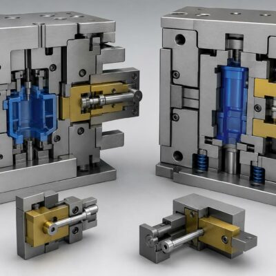
The first mold contained an upper hydraulic cylinder responsible for holding a moving core against the pressure generated during plastic injection.
The engineering calculations started with the frontal area exposed to cavity pressure.
The measured frontal surface was approximately:
28.3 cm²
The estimated cavity pressure during injection was:
500 bar
Using these values, the direct force generated by the molten plastic acting on the core reached approximately:
14,150 kgf
This value immediately demonstrates one of the most important principles of hydraulic mold design.
The injection machine may generate several hundred tons of clamp force, but individual mold components can still experience extremely high localized forces depending on their exposed surface.
Ignoring these forces may result in:
- flash formation;
- core movement;
- dimensional defects;
- premature wear;
- mechanical failure.
Why Geometry Changes Everything
Although the plastic generated more than fourteen tons of direct force, the cylinder was not required to resist all of it.
The moving insert incorporated a 10° inclined locking surface.
This mechanical geometry transformed most of the injection force into compression within the mold structure.
Consequently, the hydraulic cylinder only needed to provide approximately:
2,495 kgf of useful holding force.
This example demonstrates why hydraulic cylinders should never be selected using cavity pressure alone.
Mechanical design fundamentally changes the required hydraulic force.
Extraction Force Calculation
Once injection is completed, the loading conditions become completely different.
Instead of resisting cavity pressure, the hydraulic cylinder must now overcome the adhesion between the molded plastic and the steel insert.
The relevant parameter is no longer the frontal area.
Instead, engineers evaluate the lateral contact surface.
For the upper insert, the lateral surface measured approximately:
5.9 cm²
Using an estimated plastic adhesion coefficient of:
20 kg/cm²
the required extraction force became approximately:
118 kgf
This value is dramatically lower than the force required during injection.
It illustrates another important engineering concept.
Hydraulic cylinders rarely operate under one constant load.
The required force changes continuously throughout the molding cycle.
For this reason, every movement should be analyzed independently.
Recommended Cylinder Selection
After evaluating both loading conditions, Vega recommended the following hydraulic cylinder:
CM050CGHGQ030
Main characteristics:
- 50 mm stroke cylinder;
- stroke reducer to 30 mm;
- mechanical switches;
- nominal operating pressure of 140 bar.
The cylinder was selected not because it was the largest available, but because it supplied the required useful force while maintaining compact dimensions and appropriate operating pressure.
This approach improves reliability and reduces unnecessary hydraulic energy consumption.
Mold 21037 – Lower Cylinder
The lower cylinder operated under completely different conditions.
Unlike the upper insert, this component incorporated a mechanical shoulder capable of resisting the injection pressure.
Therefore, no pushing-force calculation was necessary.
Instead, only the extraction force needed to be evaluated.
The lateral contact surface measured approximately:
662 cm²
The draft angle was:
6.4°
Using a plastic adhesion coefficient of:
8 kg/cm²
the calculated extraction force reached approximately:
5,296 kgf.
This force is almost fifty times greater than the extraction force calculated for the upper insert.
Yet both cylinders belong to the same mold.
This clearly demonstrates why each cylinder must be sized individually.
No universal sizing rule exists.
The Influence of Part Temperature
One particularly interesting aspect of this engineering analysis concerns the effect of part temperature.
The Vega technical department observed that if the molded component were extracted at a higher temperature, the adhesion between plastic and steel would decrease.
Assuming the adhesion coefficient dropped from 8 kg/cm² to approximately 5 kg/cm², the required extraction force would decrease from:
5,296 kgf
to approximately:
3,310 kgf.
This represents a reduction of nearly 40%.
The example highlights an often-overlooked principle in injection mold engineering.
Extraction force depends not only on mold geometry but also on process conditions.
Cooling time, polymer type, mold temperature and surface finish all influence the force required to remove the molded component.
Comparing Different Mold Applications and Selecting the Right Hydraulic Cylinder
The first mold analyzed in this case demonstrated that hydraulic cylinder selection cannot be based solely on the injection pressure acting on the plastic.
Mechanical locking surfaces, draft angles, friction conditions and process parameters all influence the actual force that the hydraulic cylinder must generate.
The remaining two molds analyzed by the Vega technical department further reinforce this concept.
Although all three molds required hydraulic cylinders, the engineering calculations produced completely different force requirements and led to different cylinder selections.
Mold 21038 – Mechanical Locking Eliminates Injection Force
The second mold incorporated a design similar to the lower cylinder of Mold 21037.
A mechanical shoulder completely absorbed the force generated by the cavity pressure.
Because of this design feature, the hydraulic cylinder was not responsible for resisting the injection pressure.
Its only task was extracting the moving core after the molding cycle.
This is an excellent example of good mold engineering.
Whenever mechanical locking can safely absorb injection forces, the hydraulic cylinder can be sized only for extraction, resulting in:
- lower hydraulic pressure;
- smaller cylinders;
- lower oil consumption;
- reduced seal loading;
- longer service life.
Calculating the Extraction Force
Since only the extraction phase had to be considered, the Vega engineering department calculated the force generated by the adhesion between the molded plastic and the steel surface.
The measured lateral contact area was approximately:
115 cm²
Using an estimated plastic adhesion coefficient of:
15 kg/cm²
the calculated extraction force became approximately:
1,725 kgf, without considering additional friction.
Compared with the previous mold, this application required only about one-third of the extraction force.
The difference illustrates how strongly extraction force depends on the geometry of the molded component rather than on the overall mold size.
Recommended Hydraulic Cylinder
Based on the engineering calculations, Vega recommended the following hydraulic cylinder:
equipped with two-wire magnetic sensors.
As an alternative solution, the technical department also proposed:
CM063CGHGQ100
equipped with mechanical limit switches.
Providing alternative cylinder configurations is often advantageous because different mold makers may prefer magnetic sensing or mechanical switches depending on their maintenance procedures, control systems or machine standards.
Although the sensing technology changes, the hydraulic sizing remains exactly the same because it is determined by the calculated operating force rather than by the type of position sensor.
Mold 21039 – A Completely Different Application
The third mold demonstrates another common mistake made during hydraulic cylinder selection.
Many engineers assume that every core pull requires a relatively large cylinder.
However, the actual force depends entirely on the exposed plastic surface.
In Mold 21039 the moving elements consisted of two pins with a diameter of only 11 mm.
The combined frontal area exposed to injection pressure measured approximately:
1.7 cm²
Even assuming the same cavity pressure of 500 bar, the calculated pushing force was only:
850 kgf.
The extraction force was considered negligible because of the geometry of the application.
This represents one of the smallest hydraulic loads among the three molds.
Recommended Hydraulic Cylinder
Because of the relatively small force requirement, Vega selected a compact cylinder:
CR040018C0GHGM020
with two-wire magnetic sensors.
As an alternative, the technical department proposed:
CM040CGHGQ025
with mechanical limit switches.
This example demonstrates that increasing cylinder size simply to add a safety margin is not always beneficial.
Oversized cylinders occupy more space, consume more hydraulic oil, increase cycle time due to larger oil volumes and unnecessarily increase manufacturing costs.
Proper engineering seeks the optimum balance between safety, performance and compactness.
Why Every Hydraulic Cylinder Must Be Calculated Individually
One of the most valuable lessons from this engineering case is that the three molds required completely different hydraulic cylinder solutions despite serving similar injection molding applications.
The calculations varied because each mold had different:
- exposed frontal areas;
- lateral extraction surfaces;
- draft angles;
- plastic adhesion conditions;
- mechanical locking systems;
- extraction temperatures;
- operating strokes.
Consequently, each hydraulic cylinder had to be selected independently.
Engineering experience clearly shows that copying cylinder sizes from previous projects is rarely the correct approach.
Even apparently identical molds may generate significantly different mechanical loads.
The Importance of Plastic Adhesion
Many mold designers focus exclusively on injection pressure.
However, in numerous applications the extraction force becomes the governing design condition.
Plastic adhesion depends on several factors:
- polymer type;
- mold surface finish;
- cavity texture;
- draft angle;
- mold temperature;
- cooling time;
- shrinkage behavior;
- lubricant or mold release usage.
A change in any one of these variables can significantly alter the force required to extract the molded component.
This explains why engineering calculations frequently include different adhesion coefficients depending on the expected molding conditions.
As demonstrated in Mold 21037, a reduction in the adhesion coefficient caused by higher part temperature dramatically reduced the required extraction force.
A Structured Engineering Method
The methodology followed by the Vega technical department can be applied to virtually any hydraulic cylinder used in injection molds.
A systematic sizing procedure should include:
- Determine the frontal area exposed to cavity pressure.
- Calculate the pushing force generated during injection.
- Verify whether mechanical locking absorbs part or all of that force.
- Calculate the lateral contact surface.
- Estimate the plastic adhesion coefficient.
- Calculate the extraction force.
- Evaluate friction, guide resistance and safety factors.
- Consider process variables such as mold temperature and part extraction temperature.
- Select the hydraulic cylinder capable of generating the required useful force at the intended operating pressure.
- Verify stroke length, mounting configuration and available installation space.
Following this engineering procedure minimizes both undersizing and oversizing while improving the reliability and efficiency of the hydraulic system.
Lessons Learned from the Case
This real engineering case demonstrates that hydraulic cylinder selection should never rely on assumptions or previous experience alone.
Each moving component inside an injection mold experiences unique loading conditions.
Accurate engineering calculations allow designers to:
- reduce hydraulic energy consumption;
- avoid unnecessary oversizing;
- improve mold reliability;
- reduce maintenance costs;
- extend cylinder service life;
- minimize production downtime.
The analysis performed by the Vega technical department shows how a structured engineering approach leads to different cylinder selections for different applications, even when the molds appear similar at first glance.
Conclusion
Selecting the correct hydraulic cylinder for an injection mold is far more complex than matching bore size and stroke.
The real design process requires understanding how injection pressure, plastic adhesion, draft angles, mechanical locking systems, friction and operating temperature interact throughout the molding cycle.
The three molds analyzed in this case clearly demonstrate that every application must be evaluated individually.
A hydraulic cylinder that is perfectly suited for one mold may be completely unsuitable for another, even when both molds produce similar plastic components.
By combining accurate force calculations with sound mechanical engineering principles, mold designers can achieve higher reliability, lower hydraulic power consumption, reduced maintenance and significantly longer service life for both the hydraulic cylinders and the injection mold itself.