Holding the injection pressure sounds like a silly question: isn’t the injection press there for that purpose? Yes, it may be true, but…what about undercuts? In those spots, the injection pressure (in principle) must be held by the same devices which actuate the undercut engagement and release.
In this article, we’ll examine some methods to support the injection pressure, together with their pros and cons. Also, there’s another important subject strictly connected to this topic: stripping forces. In fact, very often we don’t have to support just the pressure, but also release the part from the mold. This implies a force for overcoming the adhesion between part and mold. Therefore, these two matters are strictly linked together and we must deal with both of them.
The main methods for holding the injection pressure are:
- Angle pins or other devices moving with the press.
- Standard hydraulic cylinders alone.
- Hydraulic cylinders with lock (an interlock driven by another cylinder or else).
- Standard hydraulic cylinders with single or multiple wedges.
- Standard hydraulic cylinder with a check valve.
- Self-locking cylinder.
- Self-locking cylinder with preload.
Let’s have a quick look at each of them.
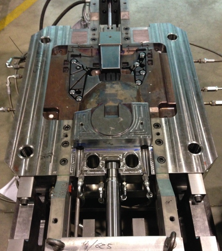
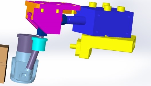
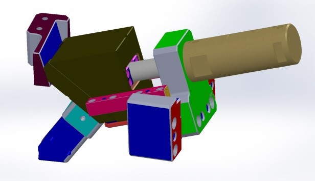
- Angle pins or other devices moving with the press.
Something similar to the pictures below.
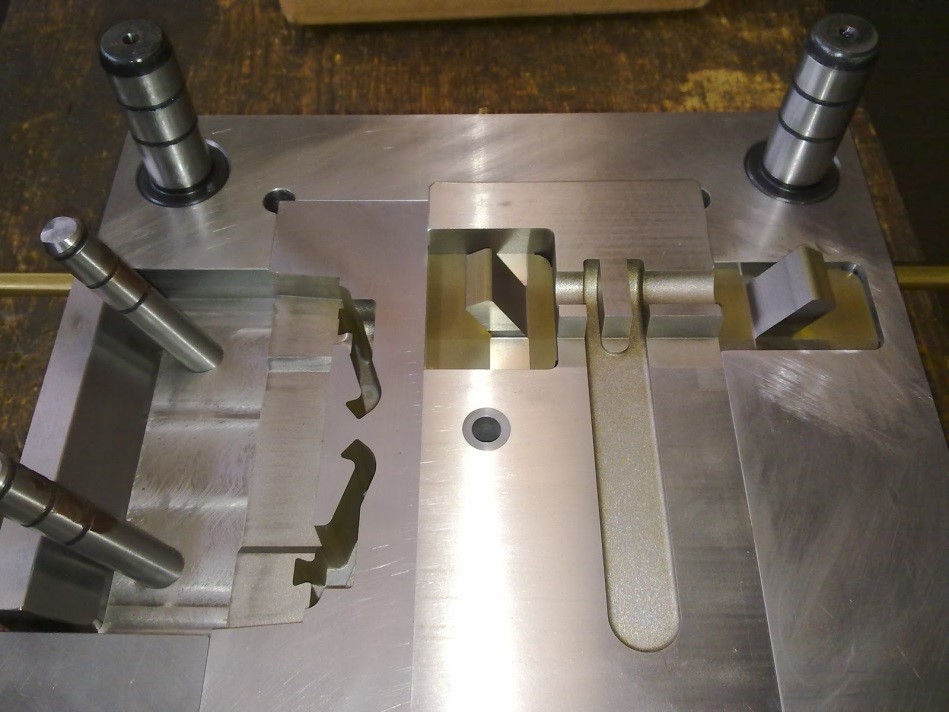
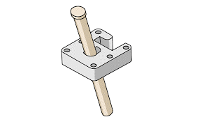
They are mechanical parts shaped according to the piece to be molded, which move with the press. Their shape must be studied according with the design of the mold.
Pros: generally easy to make, even if they clearly require some precision. As they move with the press, no further drive or actuating system is required. They are normally rather cheap and compact.
Cons: their use is limited by the mold and the shape of the part. They cannot be applied always and everywhere.
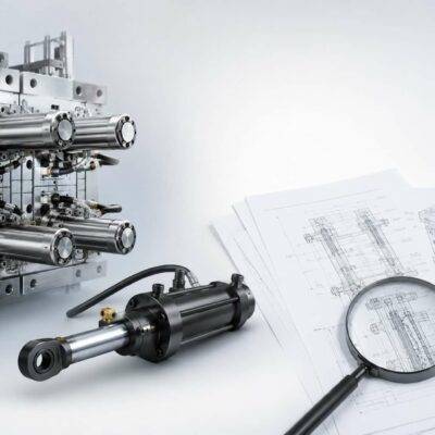
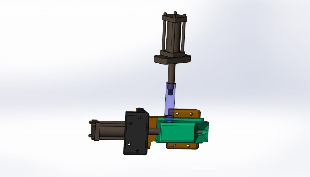
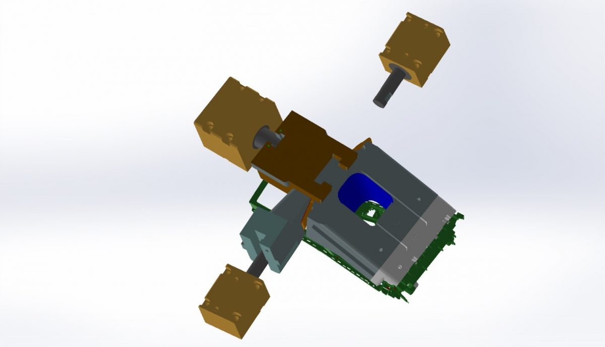
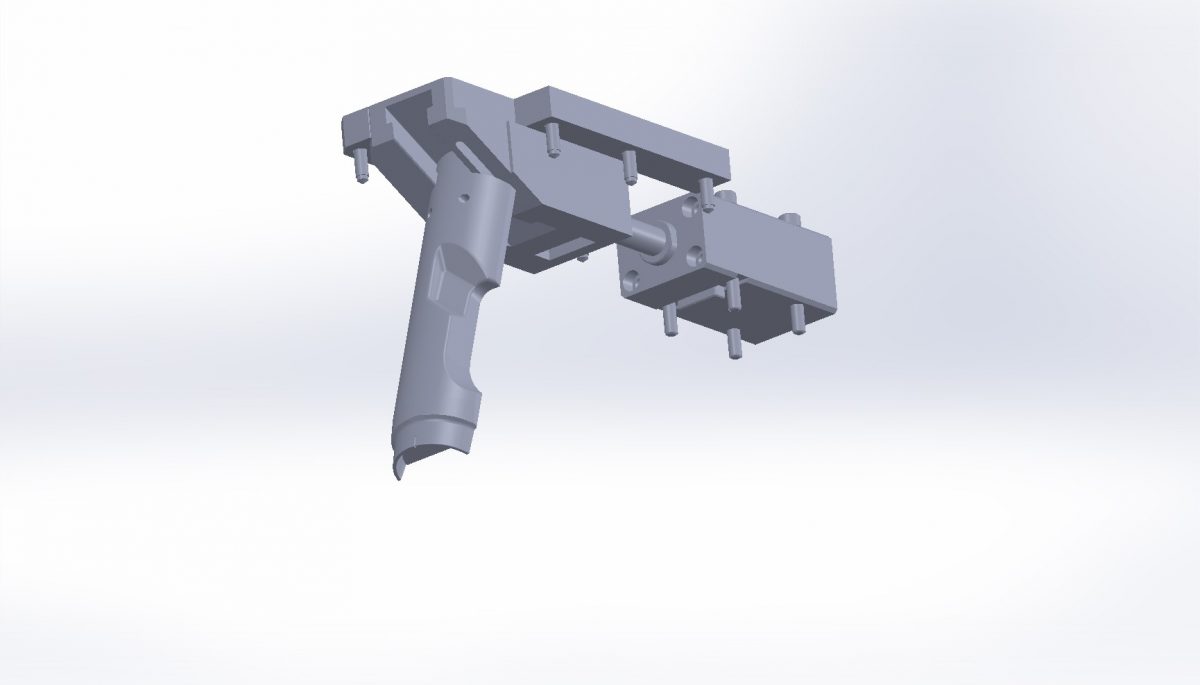
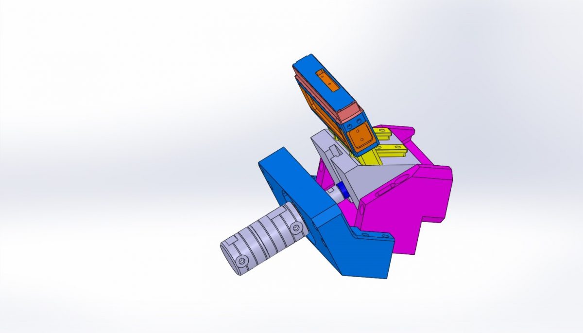
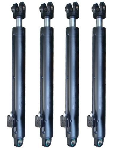
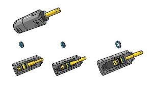
- Standard hydraulic cylinders alone.
Something similar to the pictures below.
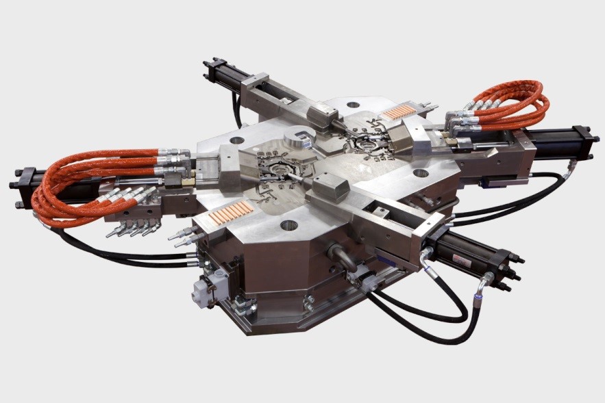
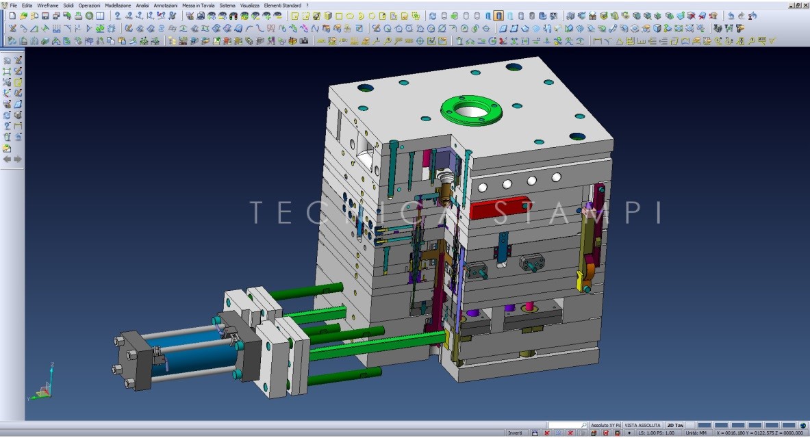
They are usually rather compact and the volume-to-force ratio is good. Of course the force they can support lies on the oil pressure and the bore (cylinder size). Their stroke can generally be as required, from just a few millimeters to many hundreds. They are independent from the press movement and can be actioned at will. This is valid for all the systems listed below.
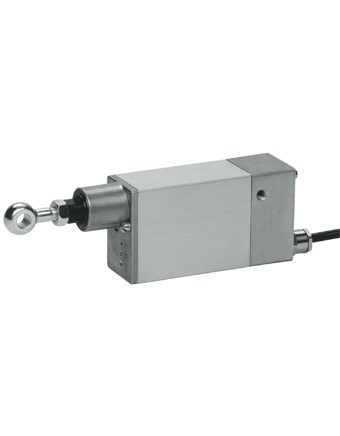
Note: sometimes, electric jacks are used instead of cylinders (see the picture). They are generally faster but force may be limited. With drive, they are expensive.
Pros: generally cheap and easy to find. It’s also easy to install them in the mold.
Cons: they require oil (as all the devices mentioned in the following points). Sometimes they are cumbersome, and other times their capacity is not enough for the forces they have to withstand.
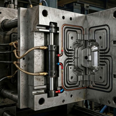
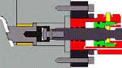
- Hydraulic cylinders with lock (an interlock driven by another cylinder or else).
Something similar to the pictures below.
As above, but with a cross bar (straight or tapered), which locks any movement along the axis of the first cylinder. Of course, the lock must be released first, then the main cylinder can return.
Pros: they can support large forces, even if they require some precision. They are usually cheaper than a self-locking cylinder (see point 6).
Cons: normally they cannot preload the core, so their use is limited if flashes are to be expected. Flash is excess material on solidified plastic parts. Traditionally, flash can be avoided either by reducing injection pressure or by increasing clamping force. Flash normally occurs when the closing surfaces spread apart a little due to injection pressure and material elasticity. A wedge-shaped lock may help but it doesn’t have the same effect as a preload on a self-locking cylinder.
Also, this system is not very compact…
- Standard hydraulic cylinders with single or multiple wedges.
Something similar to the pictures below.
A wedge can be defined as a force multiplier. It’s used everywhere, not only in molds. By using this method, a small cylinder can support forces three to four times (theoretical average) its rated capacity. It could even reach up to ten times, but this would be unpractical. If we add friction, we discover that the multiplier is much more, but the hassle comes when pulling the rod back. By the way, this method can be used in addition to others, such as angled pins.
Pros: large force with small cylinders. If we include friction, the cylinder might even be not necessary to support just the injection pressure.
Cons: Not too easy to make, as they require some precision. Not so cheap and not so compact as well. If the angle of the wedge is small, the pulling force might be not enough for stripping.
- Standard hydraulic cylinder with check valve.
Something similar to the pictures below.
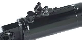
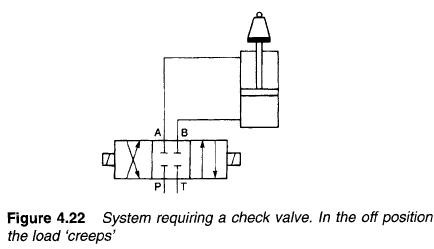
Same as normal hydraulic cylinders. The check valve lets the pressure increase at rear in the cylinder, so that the injection pressure can be supported. Anyway, as oil is actually compressible, the cylinder might bounce back and flash on the part might occur. As a rule of thumb, oil will compress about 1% for each 160 bars (on average). On the contrary, if the operating pressure (before closing the check valve) is enough to support the injection pressure, the cylinder will not bounce back.
Pros: generally easy to make, even if they require a control sequence. Great force and possibly a kind of preload could be possible. Cheap system.
Cons: this system may be useless if the cylinder rod bounces back. Please note that the deflection comes from the difference in oil compression (maximum pressure minus operating pressure). Also, if the pressure increases too much, the cylinder might break.
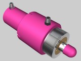
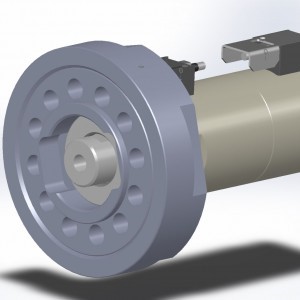
- Self-locking cylinder.
Something similar to the pictures below.
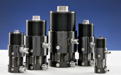
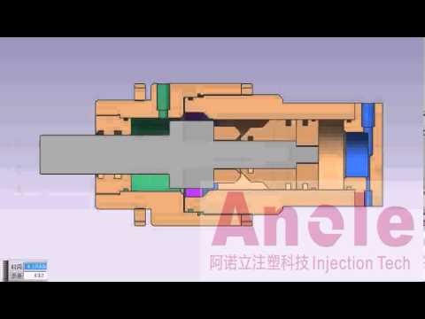
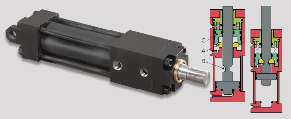
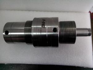
They are hydraulic cylinders having a mechanism which locks the rod in a position (normally the outermost one), allowing for a much larger retaining force than the one coming from oil pressure only. To give you an example of the holding forces possible, a standard locking cylinder with a bore of 84 mm can withstand static forces up to 700,000 N. This would require a bore size of 200 mm with a standard cylinder and an efficient check valve.
In this example, a self-locking cylinder will only work properly if the rod reaches its outermost position because only then can the segmented ring engage properly in its seat. This kind of cylinder should also perform a complete stroke-in as well, in order to operate efficiently.
Normally, oil pressure should be always applied even during injection, to keep the locking mechanism in place. Among these types of cylinders, the Vega V260CF is much appreciated because of its good balance between locking force and easiness of release.
Pros: very high holding forces and fairly high operative pressure. Very compact and flexible, due to the end of stroke switches which can be installed. Preload is applicable (see below, point 7), which enhances its flexibility even further.
Cons: cost is on the high side. Pulling force is not so high, because of the large rod and small bore normally required.
- Self-locking cylinder with preload.
Something similar to the pictures below.
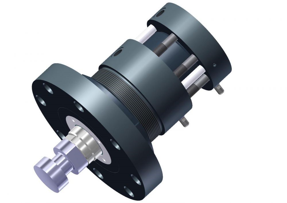
In some cases, the core must touch other parts of the cavity wall in a precise manner. Even a tiny gap can cause flash to occur. Preload can help solve this problem.
When fully out, the rod presses against a stop and is compressed. The result is a force between the two closing surfaces of the core. When the injection pressure comes, this force prevents plastic material from seeping in, so flash is avoided.
When using preload in a cylinder, it can be accomplished by using a flat flange which is slightly thicker than required. It can be precisely ground until the right thickness is achieved. Because the measurements are very precise (and small), it could take several attempts to get the correct amount of preload. This means assembling the mold, testing, disassembling the mold, grinding again the flange, and reassembling.
Another option is a threaded flange. The flange is mounted on the mold. The locking cylinder is then threaded onto the flange. This flange has a set screw that will maintain the position of the cylinder on the flange. Preload can then be adjusted by releasing the set screw and turning the cylinder in small increments to move it forward or backward. Tighten the set screw and you are ready to test again. Other flange types are also available.
Pros: same as the self-locking cylinder, and perfect final result on the molded part.
Cons: as part of the cylinder capacity is used for obtaining the preload, total admissible force is less than usual. Increased costs.
Conclusion:
The perfect system has yet to come. It should be cheap, capable of supporting a huge force due to injection and giving a very high stripping force. None of the systems seen until now has all these pros…
However, the self-locking cylinder with a preload capability appears to be the most flexible and compact system to support injection pressure, both in plastic and pressure die casting sectors.