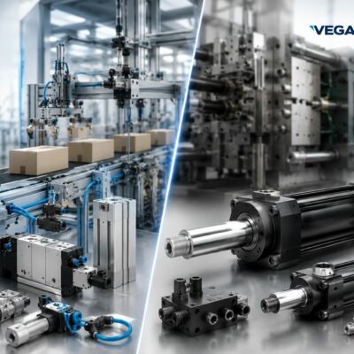
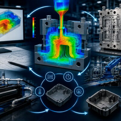
A Real Engineering Case on Magnetic Sensors, SIM08 Modules and Injection Mold Control Systems
Modern injection molds often incorporate several hydraulic cylinders operating simultaneously within the same mold.
Each cylinder must be monitored to verify that it has reached the required position before the molding cycle can continue safely.
For this reason, almost every hydraulic cylinder used in injection molding applications is equipped with two position sensors:
- one sensor confirming the fully retracted position;
- one sensor confirming the fully extended position.
As the number of cylinders increases, the number of electrical signals grows rapidly.
A mold equipped with six hydraulic cylinders, for example, requires twelve magnetic position sensors.
Connecting every sensor directly to the PLC means increasing:
- the number of electrical cables;
- the number of PLC digital inputs;
- wiring complexity;
- installation time;
- commissioning effort;
- the possibility of wiring errors.
To simplify this architecture, interface modules such as the SIM08 are used.
Rather than sending every sensor signal individually to the PLC, these modules collect multiple sensor inputs and transmit only the information that the machine actually requires.
This real engineering case explains how the Vega Technical Department assisted a customer in configuring molds equipped with three and six hydraulic cylinders, providing the correct wiring diagrams for one or two SIM08 modules and the proper DIP switch configuration.
The Customer’s Challenge
The customer had purchased eighteen hydraulic cylinders for four different injection molds.
Two molds were equipped with:
- 3 hydraulic cylinders
while the remaining two molds contained:
- 6 hydraulic cylinders.
As a result, two different SIM08 configurations were required:
- one SIM08 module for molds with three cylinders;
- two interconnected SIM08 modules for molds with six cylinders.
Besides the wiring diagrams, the customer also requested detailed instructions regarding:
- DIP switch configuration;
- tester connections;
- machine wiring;
- connector numbering.
This technical support request eventually became much more interesting than a simple wiring question.
It highlighted one of the most common misunderstandings encountered when integrating hydraulic components with industrial control systems.
Why the Number of Sensors Increases So Quickly
Every hydraulic cylinder installed in an injection mold normally requires confirmation of two operating positions:
- fully retracted;
- fully extended.
Therefore, every cylinder typically uses two magnetic sensors.
The total number of sensors becomes:
| Number of Cylinders | Number of Sensors |
|---|---|
| 1 | 2 |
| 2 | 4 |
| 3 | 6 |
| 4 | 8 |
| 6 | 12 |
With six cylinders, the mold already requires twelve electrical position signals.
Routing twelve independent sensor cables from the mold to the machine quickly increases both electrical complexity and installation cost.
What Is the Purpose of the SIM08?
The SIM08 was specifically developed to simplify this type of installation.
Its purpose is not to replace the PLC.
Instead, it serves as an interface between the mold and the machine by:
- collecting signals from multiple magnetic sensors;
- reducing the number of machine connections;
- simplifying mold wiring;
- reducing installation time;
- improving maintenance efficiency.
In practice, the SIM08 acts as a signal concentrator, allowing the machine to receive only the position information required for safe cycle management.
This approach significantly reduces the number of wires passing through the mold connector.
The Misunderstanding That Started This Technical Case
The most valuable aspect of this case is not the wiring itself.
It is the misunderstanding regarding how the SIM08 operates.
During the email exchange, the customer requested an independent output signal for every individual sensor, expecting to monitor each hydraulic cylinder separately.
From the customer’s perspective, this seemed perfectly reasonable.
If there are twelve sensors, one might naturally expect twelve independent outputs.
However, the Vega Technical Department explained that this is not how the SIM08 is designed to operate.
How the SIM08 Actually Works
The response from the Vega Technical Department clarified one of the key design principles of the SIM08.
The module connects the magnetic sensors in series, rather than providing an independent output for each sensor.
Instead of generating twelve separate PLC inputs, the SIM08 provides only:
- one Forward confirmation signal;
- one Back confirmation signal.
Consequently, the SIM08 cannot be used to monitor each magnetic sensor independently.
This is not a limitation of the device.
It is an intentional engineering design choice.
In most injection molding applications, the PLC does not need to know which cylinder reached its position first.
The only information required is whether all cylinders have successfully completed the commanded movement.
Why the Sensors Are Connected in Series
Many mold movements must be completed simultaneously before the molding cycle is allowed to continue.
Typical examples include:
- all side cores fully closed;
- all slides correctly positioned;
- all hydraulic cylinders fully extended;
- all hydraulic cylinders fully retracted.
Only when every actuator reaches the required position does the PLC authorize the next production step.
For this reason, series-connected position sensors provide a simple, reliable and highly efficient solution.
Instead of continuously monitoring twelve independent inputs, the PLC only needs to verify the presence of a single Forward signal or a single Back signal.
This dramatically simplifies both electrical wiring and PLC programming.
How to Connect Two SIM08 Modules Correctly
In the case analyzed, the customer needed to manage two different mold configurations.
The first configuration included three hydraulic cylinders.
The second included six hydraulic cylinders.
For molds equipped with six cylinders, the Vega Technical Department recommended using two SIM08 modules connected in series, providing detailed wiring instructions and the correct DIP switch configuration.
This solution allows the machine control logic to remain unchanged while increasing the number of monitored cylinders.
The operating principle remains exactly the same:
all sensors corresponding to a given position must confirm that every cylinder has completed its movement before a confirmation signal is transmitted to the PLC.
Wiring Three Hydraulic Cylinders
For molds equipped with three hydraulic cylinders, the Vega Technical Department supplied a straightforward wiring table.
Each cylinder uses:
- one Back magnetic sensor;
- one Forward magnetic sensor.
The SIM08 connector allocation is:
| Cylinder | Back Sensor | Forward Sensor |
|---|---|---|
| Cylinder 1 | Connector 1 | Connector 2 |
| Cylinder 2 | Connector 3 | Connector 4 |
| Cylinder 3 | Connector 5 | Connector 6 |
This configuration allows a single SIM08 module to monitor all three cylinders while keeping the electrical installation simple and well organized.
Wiring Six Hydraulic Cylinders
When the number of hydraulic cylinders doubles, the number of position sensors also doubles.
Six cylinders require twelve magnetic sensors.
To manage these signals efficiently, two SIM08 modules are connected together.
The Vega Technical Department recommended the following allocation.
SIM08 No. 1
- Cylinder 1 → Connectors 1–2
- Cylinder 2 → Connectors 3–4
- Cylinder 3 → Connectors 5–6
SIM08 No. 2
- Cylinder 4 → Connectors 1–2
- Cylinder 5 → Connectors 3–4
- Cylinder 6 → Connectors 5–6
The two SIM08 modules are then connected in series and provide the machine with only the final Forward and Back confirmation signals.
DIP Switch Configuration
One of the issues that generated the greatest confusion during installation concerned the DIP switch settings.
The Vega Technical Department clearly specified that, when using two SIM08 modules for six hydraulic cylinders, both modules must use the same DIP switch configuration:
- DIP Switch 1 → ON
- DIP Switch 2 → ON
- DIP Switch 3 → ON
- All remaining DIP switches → OFF.
Incorrect DIP switch settings may prevent the system from operating correctly or generate incorrect confirmation signals during the molding cycle.
For this reason, DIP switch verification should always be included in the commissioning procedure.
Tester Connections and Machine Wiring
During the project, the customer also asked whether the wiring used with the portable tester was identical to the wiring used on the injection molding machine.
To eliminate any uncertainty, the Vega Technical Department supplied:
- complete wiring diagrams;
- photographs showing the tester connections;
- photographs illustrating two interconnected SIM08 modules;
- a complete schematic showing the connection between the SIM08 modules and the machine terminal box.
Providing visual documentation significantly reduced installation errors and simplified machine commissioning.
This case highlights the importance of combining written technical instructions with practical wiring diagrams.
Why Twelve Independent Signals Are Not Always Better
Many engineers initially assume that receiving more signals automatically provides better machine control.
In practice, every additional PLC input introduces:
- more electrical wiring;
- larger connectors;
- increased programming complexity;
- longer commissioning time;
- additional diagnostic procedures;
- higher maintenance costs.
When all hydraulic cylinders are required to complete the same movement simultaneously, twelve independent signals provide little practical benefit.
One common Forward confirmation and one common Back confirmation are generally sufficient.
This engineering philosophy allows simpler electrical systems, more reliable machine operation and lower installation costs.
When Independent Signals Are Necessary
There are, however, applications where monitoring every cylinder individually becomes essential.
Examples include:
- molds with independent movement sequences;
- servo-hydraulic systems;
- Industry 4.0 applications requiring complete traceability;
- predictive maintenance systems;
- PLC programs that must identify exactly which cylinder has failed to reach its commanded position.
In these situations, each magnetic sensor typically requires its own dedicated PLC input or a distributed I/O architecture.
The SIM08 was developed for a different objective:
to simplify wiring while maintaining reliable position confirmation for synchronized hydraulic movements.
Lessons Learned from This Real Engineering Case
One of the most valuable lessons from this technical support case is that many installation problems originate not from faulty hardware but from misunderstandings regarding the intended function of the equipment.
The customer expected the SIM08 to behave like a signal acquisition module capable of providing one output for every individual magnetic sensor.
The Vega Technical Department clarified that the SIM08 was designed to combine multiple position signals into only two confirmation outputs for the PLC.
Understanding the operating philosophy of a system before installation prevents design errors, reduces commissioning time and allows engineers to take full advantage of the module’s capabilities.
Engineering Conclusions
Integrating hydraulic cylinders with electronic control systems requires more than simply connecting electrical cables.
Engineers must also understand how position signals are processed and how the PLC interprets those signals during machine operation.
In this real engineering case, the Vega Technical Department assisted the customer in configuring both three-cylinder and six-cylinder molds, defining the correct SIM08 wiring, connector allocation and DIP switch configuration.
The most important technical conclusion is that the SIM08 was never intended to generate one independent output for every magnetic sensor.
Instead, it aggregates multiple sensor signals and provides only the Forward and Back confirmation signals required by the PLC, reducing wiring complexity, simplifying PLC programming and improving the overall reliability of the control system.
The key lesson is straightforward:
A well-designed automation system is not the one that transmits the greatest number of signals, but the one that delivers exactly the information required for safe, reliable and efficient machine operation.