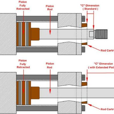
In hydraulic applications, the required stroke is not always available as a standard cylinder configuration. When a suitable hydraulic cylinder is already available, replacing it with another model is not necessarily the most efficient solution.
A Vega case study from 2016 provides a clear example: a customer had a CE25EGDGM020 + MSU2 hydraulic cylinder with a 20 mm stroke, but the application required only 10 mm of movement. Instead of replacing the cylinder, Vega proposed a mechanical solution based on an internal aluminium/Ergal spacer.
The solution is also consistent with Vega’s technical documentation, which specifically describes the use of spacers for special cylinder strokes.
The Application Challenge
The customer had a CE25EGDGM020 + MSU2 cylinder already available in stock.
The cylinder provided a 20 mm stroke, while the application required the movement to be limited to 10 mm. The customer asked Vega for technical instructions, including the material and dimensions required to modify the cylinder.
This created a straightforward engineering requirement:
Standard stroke: 20 mm
Required stroke: 10 mm
The challenge was therefore not to increase the cylinder’s performance, but to create a reliable mechanical limitation of its effective stroke.
Vega’s Solution: An Internal Spacer
Vega’s technical team proposed installing an aluminium/Ergal spacer inside the hydraulic cylinder to reduce the available stroke from 20 mm to 10 mm.
The concept is simple: the spacer occupies part of the cylinder’s original stroke, creating a mechanical stop before the piston can complete the full 20 mm movement.
This approach can be particularly useful when a standard cylinder is already available and the required application movement is shorter than its nominal stroke.
The solution in numbers
| Parameter | Original | Required |
|---|---|---|
| Cylinder stroke | 20 mm | 10 mm |
| Stroke reduction | — | 10 mm |
| Spacer material | — | Aluminium / Ergal |
| Cylinder | CE25EGDGM020 + MSU2 | Same cylinder |
The Case 220 documentation specifically states that the spacer was to be manufactured in aluminium/Ergal.
The Vega Manual Supports the Use of Spacers for Special Strokes
This is an important point because the case is not simply an isolated workaround.
Vega’s hydraulic-cylinder documentation states that non-standard strokes can be supplied on request and that, for special strokes, a guide spacer can be considered in consultation with the technical department. The same documentation gives a stroke tolerance of −0/+0.5 mm.
The manual also identifies the V250CE as an alternative compact cylinder for strokes below 80 mm.
This provides useful technical context for Case 220: the use of a spacer to obtain a special stroke is consistent with Vega’s documented engineering approach.
The V250CE and Short-Stroke Applications
The current Vega documentation describes the V250CE as a compact, short-stroke hydraulic-cylinder series. Standard configurations have bore sizes from 25 to 100 mm and strokes from 20 to 80 mm.
The Ø25 mm configuration with a 20 mm stroke is also present in Vega’s technical catalog, matching the dimensional family involved in this case.
V250CE Short-Stroke Compact Hydraulic Cylinders
Vega positions the V250CE for compact movements in plastic injection molds, including applications involving carts, pins and plugs that create undercuts.
Hydraulic Cylinders for Cart and Plug Movement
How the Spacer Is Installed
The Case 220 instructions are particularly valuable because they do not simply specify the spacer; they describe how it should be mechanically secured.
First, the aluminium/Ergal spacer is inserted over the cylinder rod and must remain perfectly seated and locked against the piston.
Once the spacer is correctly positioned, Vega instructed the customer to:
- Drill the rod using a 4.2 mm drill.
- Limit the drilling depth to a maximum of 5 mm.
- Align the hole with the M5 threaded hole in the spacer.
- Tap the hole to M5 while keeping the spacer locked in position.
- Install an M5 × 5 or M5 × 6 stainless-steel grub screw.
- Apply a drop of Loctite 243 during assembly.
There was also an important dimensional precaution: the head of the grub screw had to remain inside the external diameter of the spacer, without protruding.
Why the Fixing Method Matters
Reducing a cylinder’s effective stroke is not simply a matter of placing an object inside the cylinder.
The spacer must remain correctly positioned throughout operation. For this reason, the Case 220 instructions specify both the machining procedure and the mechanical locking method.
The sequence is particularly important:
Position spacer → lock spacer → drill rod → tap M5 → install grub screw → verify screw does not protrude
This turns a simple spacer into a controlled mechanical component of the cylinder assembly.
Standard Cylinder or Special Stroke?
Vega’s current product documentation confirms that hydraulic cylinders for injection molds can be configured with different bore and stroke combinations, while also allowing customized configurations according to customer requirements.
Vega Hydraulic Cylinders for Injection Molds
The current V250CE product range lists standard strokes of 20, 50 and 80 mm for the configurations shown online.
V250CE Block Cylinders – Standard Configurations
When the required stroke does not correspond to a standard configuration, Vega’s technical documentation provides a route toward a special-stroke solution, including the possible use of a spacer.
An Efficient Alternative to Cylinder Replacement
Case 220 demonstrates an important aspect of hydraulic-cylinder engineering: the cylinder does not always need to be replaced when the required stroke changes.
In this particular application, the customer already had the correct cylinder available. The requirement was simply to reduce its effective movement from 20 mm to 10 mm.
Vega therefore developed a spacer-based solution that:
- used the existing hydraulic cylinder;
- reduced the effective stroke by 10 mm;
- used aluminium/Ergal for the spacer;
- provided a defined mechanical fixing method;
- specified the drilling and tapping procedure;
- used a stainless-steel M5 grub screw;
- incorporated Loctite 243 to secure the fixing.
The solution is consistent with Vega’s broader documentation concerning special cylinder strokes and the use of spacers for non-standard movements.
Engineering Lessons from Case 220
The case illustrates three useful principles for hydraulic-cylinder applications.
1. A standard cylinder can sometimes be adapted to a specific stroke requirement
A 20 mm standard stroke was not suitable for the application, but the cylinder itself remained usable.
2. Stroke reduction must be mechanically controlled
The spacer was not simply inserted loosely. Vega specified its position, drilling procedure, M5 thread and mechanical locking method.
3. Special strokes should be treated as an engineering requirement
Vega’s technical documentation explicitly recognizes special strokes and identifies spacer solutions as one possible approach.
Therefore, a special-stroke requirement should be evaluated as part of the cylinder design rather than treated as an improvised modification.
Conclusion
Case 220 is a practical example of how a hydraulic-cylinder stroke can be adapted to meet a specific application requirement.
A customer needed to reduce the stroke of a CE25EGDGM020 + MSU2 cylinder from 20 mm to 10 mm. Vega proposed an aluminium/Ergal internal spacer, together with a defined machining and fastening procedure using an M5 stainless-steel grub screw and Loctite 243.
Vega’s technical documentation further confirms that spacers can be considered for special cylinder strokes, supporting the engineering principle demonstrated by this case.
The result is a good example of practical hydraulic engineering: when the cylinder is suitable but the standard stroke is not, a properly engineered special-stroke solution can sometimes avoid replacing the complete cylinder.