

A practical guide to calculating thrust force, traction force, cylinder size and preload
Hydraulic locking cylinders are widely used in injection molds to hold slides, cores and other moving mold components securely in position during the injection process.
Correct cylinder selection is not simply a matter of choosing a cylinder according to the available space or the nominal size of the slide.
The cylinder must be able to withstand the forces generated by the plastic during injection and, at the same time, the mechanical structure supporting the cylinder must be capable of transmitting those forces without excessive deformation.
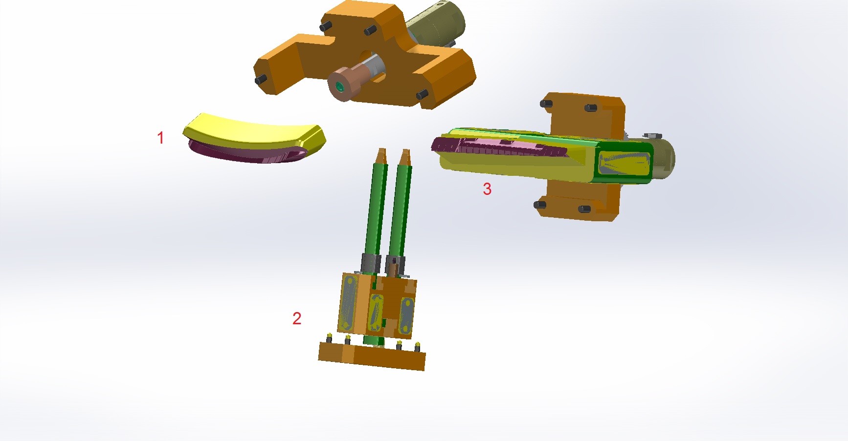
A technical analysis carried out by Vega for an injection mold provides a useful example involving three different slides, each requiring a different hydraulic cylinder.
The analysis considered two fundamental loads:
- thrust force, generated by the pressure of the plastic acting on the frontal surface;
- traction force, associated with plastic adhesion acting on the lateral surface.
The resulting calculations led to the selection of three different cylinders: CF084, CM050 and CF071, depending on the specific slide and load conditions.
1. Why Locking Force Is Important in Injection Molds
During injection, molten plastic is introduced into the cavity at high pressure.
This pressure acts on the surfaces of the mold cavity and on any movable components forming the part.
When a slide is used, the pressure can generate a force tending to move the slide away from its intended position.
If the slide is not adequately locked, this force can cause:
- movement of the slide;
- flash on the molded component;
- dimensional errors;
- damage to the mold;
- premature wear of the locking mechanism.
The hydraulic locking cylinder therefore has to generate sufficient force to keep the slide securely in position.
However, the required force depends on the geometry of the molded part and the surface exposed to the plastic pressure.
2. The First Step: Determine the Frontal Surface
The first calculation performed by Vega was the thrust force calculation.
The starting parameter is the total frontal surface exposed to the plastic pressure.
For the first slide, Vega calculated:
Total frontal surface: approximately 173.7 cm²
and estimated the plastic pressure in the cavity at:
350 bar.
The resulting thrust force was:
60,795 kgf.
This is an extremely large force.
It immediately demonstrates why the locking system cannot be selected simply by looking at the physical dimensions of the slide.
The actual projected surface exposed to injection pressure is much more important.
3. Thrust Force and Injection Pressure
The basic relationship is straightforward:
where:
- F = force;
- P = pressure;
- A = surface area.
In an injection mold, the pressure acting on the projected surface of the plastic part generates the force tending to open or move the relevant mold component.
For the first slide, Vega used:
- frontal surface = 173.7 cm²;
- estimated cavity pressure = 350 bar.
The calculated result was:
60,795 kgf.
The exact calculation documented by Vega should be considered the reference for this application.
4. Why Projected Area Matters More Than Part Size
A common mistake is to estimate the force required to lock a slide simply from the overall dimensions of the molded part.
The relevant parameter is instead the surface exposed to the pressure acting in the direction that tends to move the slide.
Two molded parts with similar external dimensions can therefore require very different locking forces.
For example:
- a large part with a relatively small projected area may generate a moderate force;
- a smaller part with a large projected area may generate a much higher force.
This is why projected frontal area should be determined before selecting the locking cylinder.
5. The Second Calculation: Traction Force
Vega also calculated the traction force.
This calculation considers the lateral surface and the adhesion of the plastic to the mold component.
For the first slide, the documented values were:
- total lateral surface: 187.4 cm²;
- plastic adhesion coefficient: 20 kg/cm²;
- traction force: 3,747.6 kgf.
The simplified relationship is:
where:
- Aₗₐₜₑᵣₐₗ = lateral surface;
- k = plastic adhesion coefficient.
In this application, Vega used an adhesion coefficient of 20 kg/cm².
6. Thrust Force and Traction Force Are Different
These two calculations should not be confused.
Thrust force
This is associated with the pressure of the plastic acting on the frontal/projected surface.
Traction force
This calculation considers the lateral surface and the assumed plastic adhesion coefficient.
For the first slide:
| Parameter | Value |
|---|---|
| Frontal surface | 173.7 cm² |
| Plastic pressure | 350 bar |
| Thrust force | 60,795 kgf |
| Lateral surface | 187.4 cm² |
| Adhesion coefficient | 20 kg/cm² |
| Traction force | 3,747.6 kgf |
The two values describe different loading conditions and should be evaluated according to the actual function of the locking system.
7. Selecting the Cylinder for the First Slide
Based on the calculations, Vega proposed a:
CF084
The documented recommendation was:
- CF084
- minimum working pressure: 140 bar
- maximum preload: 0.05–0.08 mm.
The minimum working pressure is particularly important.
The cylinder must be capable of generating the required locking force at the pressure available in the hydraulic circuit.
Therefore, cylinder selection must consider both:
required mechanical force
and
available hydraulic pressure.
8. Why Hydraulic Pressure Matters
The force generated by a hydraulic cylinder depends on:
- piston area;
- hydraulic pressure.
In simplified form:
where:
- F = cylinder force;
- P = hydraulic pressure;
- Aₚ = effective piston area.
Therefore, the same cylinder can generate different forces at different hydraulic pressures.
This is why Vega specified that the CF084 should operate at a minimum working pressure of 140 bar for the application considered.
9. The Importance of Preload
The CF084 recommendation also includes a specific preload condition:
maximum preload: 0.05–0.08 mm.
Preload is an important parameter in hydraulic locking applications.
The purpose is to ensure that the locking element is correctly positioned and that the system has the necessary mechanical contact when the mold is subjected to injection forces.
However, preload should not be considered independently from:
- cylinder geometry;
- mold design;
- locking surface;
- available hydraulic pressure;
- mechanical tolerances.
The value specified by Vega applies to this particular application and should not automatically be transferred to every CF084 installation.
10. Why the Cylinder Support Can Become a Problem
One of the most important observations in the Vega analysis concerns the support where the cylinder is fixed.
Vega noted that this support could flex under the calculated force.
This is a crucial point.
It is not sufficient to calculate:
“The cylinder generates enough force.”
The engineer must also ask:
“Can the structure supporting the cylinder withstand that force without excessive deformation?”
A powerful cylinder installed on an insufficiently rigid support can create a new problem.
11. Cylinder Force Must Be Transferred Into the Mold Structure
The load path can be represented as:
hydraulic pressure
↓
cylinder
↓
locking component
↓
slide
↓
mold structure
Every component in this chain must be capable of transmitting the load.
If one component is too flexible, the locking force may cause deformation instead of effectively locking the slide.
In the first application, Vega therefore recommended increasing the number of fixing screws and arranging them in symmetrical and equidistant positions.
12. Why the Fixing Screws Matter
The fixing screws are not merely used to hold the cylinder in place.
They are part of the load-transfer system.
If the cylinder generates a very high locking force, the support and fixing system must prevent:
- movement;
- rotation;
- deformation;
- local bending.
For the first slide, Vega specifically recommended:
increasing the number of fixing screws and positioning them symmetrically and at equal distances.
This is a valuable general design principle.
13. The Second Slide
The second slide had significantly smaller surfaces.
Vega calculated:
- total frontal surface: 5.2 cm²;
- estimated plastic pressure: 350 bar;
- thrust force: 1,820 kgf.
For the traction calculation:
- total lateral surface: 18.7 cm²;
- plastic adhesion coefficient: 20 kg/cm²;
- traction force: 374 kgf.
The recommended cylinder was:
CM050
Vega specified that the CM050 could be used with or without a check valve for this application.
This illustrates an important principle:
Cylinder selection is application-specific.
The first slide required a CF084, while the considerably smaller second slide could be handled by a CM050.
14. Why the Same Cylinder Should Not Automatically Be Used Everywhere
It might be tempting to use the same cylinder for all slides in a mold.
Sometimes this can be practical, but it is not necessarily the technically optimal solution.
The three slides in this application demonstrate why.
The calculated forces are different:
Slide 1
60,795 kgf thrust
Slide 2
1,820 kgf thrust
Slide 3
35,945 kgf thrust
Using one cylinder size for all three would therefore potentially mean either:
- oversizing the smaller application;
- or inadequately sizing the larger application.
15. The Third Slide
The third slide represents another high-load application.
Vega calculated:
- total frontal surface: 102.7 cm²;
- estimated plastic pressure: 350 bar;
- thrust force: 35,945 kgf.
The traction calculation produced:
- total lateral surface: 89 cm²;
- plastic adhesion coefficient: 20 kg/cm²;
- traction force: 1,780 kgf.
The recommended cylinder was:
CF071
with:
maximum preload: 0.15 mm.
16. Comparing the Three Applications
The complete calculation can be summarized as follows:
| Slide 1 | Slide 2 | Slide 3 | |
|---|---|---|---|
| Frontal surface | 173.7 cm² | 5.2 cm² | 102.7 cm² |
| Plastic pressure | 350 bar | 350 bar | 350 bar |
| Thrust force | 60,795 kgf | 1,820 kgf | 35,945 kgf |
| Lateral surface | 187.4 cm² | 18.7 cm² | 89 cm² |
| Adhesion coefficient | 20 kg/cm² | 20 kg/cm² | 20 kg/cm² |
| Traction force | 3,747.6 kgf | 374 kgf | 1,780 kgf |
| Recommended cylinder | CF084 | CM050 | CF071 |
| Preload | 0.05–0.08 mm | — | 0.15 mm |
This table demonstrates how strongly cylinder selection depends on the geometry of the specific application.
17. Why the Plastic Pressure Is So Important
Vega used an estimated cavity pressure of:
350 bar
for all three slide calculations.
Because the force is directly related to pressure and area, an increase in cavity pressure would increase the resulting force for the same projected surface.
This means that cylinder sizing cannot be separated from the molding process.
The designer needs to know the pressure assumption used for the calculation.
18. Why the Customer Should Verify the Calculation
At the end of the technical analysis, Vega stated:
“This are the results of my calculations, I suggest to the customer to do his verifications.”
This is an important engineering principle.
A cylinder selection based on a technical calculation is only as reliable as the input data.
The customer should therefore verify:
- actual cavity pressure;
- actual molded-part geometry;
- projected surfaces;
- lateral surfaces;
- adhesion conditions;
- mold structure;
- hydraulic pressure available;
- cylinder installation;
- fixing arrangement.
The values calculated by Vega provide a technical basis for the selection, but the final mold designer remains responsible for verifying the complete application.
19. What Happens if the Support Flexes?
The first slide provides a particularly useful lesson.
Vega calculated a very high thrust force of:
60,795 kgf.
The Technical Department then warned that the support where the cylinder is mounted could flex under this force.
This means the mechanical design cannot stop at cylinder selection.
The support must also be checked.
If the support deforms, the actual locking position can change.
This can lead to:
- loss of effective preload;
- displacement of the locking element;
- uneven load distribution;
- additional stress on the mold structure.
The solution suggested by Vega was to reinforce the fixing arrangement by increasing the number of screws and placing them symmetrically and equidistantly.
20. Symmetrical Fixing Is a Useful Design Principle
When a cylinder generates a large force, the fixing points should be arranged so that the load is transferred into the support as uniformly as possible.
A symmetrical arrangement helps reduce:
- eccentric loading;
- local deformation;
- twisting;
- uneven stress around the mounting area.
For this reason, Vega specifically recommended that the additional fixing screws be placed in specular and equidistant positions.
This recommendation is particularly relevant for high-force locking applications.
21. Locking Cylinder Sizing: A Practical Workflow
A useful workflow for designing a hydraulic locking system is:
Step 1 — Determine the projected frontal surface
Calculate the surface exposed to the injection pressure.
Step 2 — Establish the design pressure
Determine the cavity pressure to be used for the calculation.
Step 3 — Calculate the thrust force
Use the pressure and projected surface.
Step 4 — Determine the lateral surface
Calculate the relevant surface for the traction calculation.
Step 5 — Apply the adhesion coefficient
Use the appropriate coefficient for the application.
Step 6 — Calculate the traction force
Determine the resulting force.
Step 7 — Select the cylinder
Choose a cylinder capable of providing the required locking force at the available hydraulic pressure.
Step 8 — Determine the preload
Respect the preload specified for the selected application.
Step 9 — Check the cylinder support
Verify that the support can withstand the resulting forces without excessive deformation.
Step 10 — Verify the fixing screws
Check number, position, symmetry and mechanical strength.
Step 11 — Verify the complete mold
The cylinder, support, slide and mold structure must work together as one mechanical system.
22. The Cylinder Is Only One Part of the Locking System
A common design mistake is to focus entirely on the cylinder.
But the actual system is:
cylinder
mounting
locking element
slide
mold structure
The cylinder may be capable of generating the required force, but if the support bends, the locking system may not perform correctly.
The opposite is also true.
A very rigid support cannot compensate for an undersized cylinder.
Correct design therefore requires both:
hydraulic capacity
and
mechanical structural capacity.
23. The Difference Between Thrust and Traction Must Be Considered
Another important lesson from this application is that the locking system can be subjected to different force directions.
The frontal pressure generates the large thrust force.
The lateral surface and adhesion assumption produce the traction force.
These forces should be analyzed according to the actual geometry and movement of the slide.
For the first slide, the difference is particularly large:
60,795 kgf thrust
versus
3,747.6 kgf traction.
For the third slide:
35,945 kgf thrust
versus
1,780 kgf traction.
This demonstrates why a single simplified force value may not adequately describe the complete mechanical loading condition.
24. Why Mold Geometry Determines Cylinder Size
The three slides demonstrate the direct relationship between mold geometry and cylinder selection.
The first slide has:
173.7 cm² frontal surface
and requires a:
CF084.
The second has only:
5.2 cm²
and requires a:
CM050.
The third has:
102.7 cm²
and requires a:
CF071.
The cylinder therefore follows the application.
It is not the other way around.
25. A Practical Design Checklist
Before selecting a hydraulic locking cylinder for an injection mold slide, verify:
Mold geometry
- Frontal/projected surface
- Lateral surface
- Slide geometry
- Direction of injection pressure
Process parameters
- Estimated cavity pressure
- Plastic material
- Adhesion assumption
Force calculation
- Thrust force
- Traction force
- Resulting load direction
Cylinder
- Bore
- Working pressure
- Required force
- Preload
- Stroke
- Suitable locking configuration
Mechanical structure
- Cylinder support rigidity
- Fixing screw quantity
- Screw position
- Symmetry
- Equidistant arrangement
- Mold plate strength
Final verification
- Customer calculation
- Actual mold conditions
- Hydraulic pressure available
- Mechanical verification of the complete assembly
26. The Most Important Lesson From This Application
The most important lesson is that hydraulic-cylinder selection cannot be separated from mold-force calculation.
The correct sequence is:
mold geometry
↓
projected surface
↓
cavity pressure
↓
thrust force
↓
lateral surface
↓
adhesion coefficient
↓
traction force
↓
cylinder selection
↓
preload
↓
support and fixing verification
This is much more reliable than selecting a cylinder simply because its physical dimensions appear suitable.
Conclusion
The correct sizing of a hydraulic locking cylinder for an injection mold begins with the forces generated by the molding process.
In the technical application analyzed by Vega, three different slides were evaluated using the same estimated cavity pressure of 350 bar but with very different surface areas.
The first slide had a frontal surface of 173.7 cm², resulting in a calculated thrust force of 60,795 kgf and a traction force of 3,747.6 kgf. Vega recommended a CF084, with a minimum working pressure of 140 bar and a maximum preload of 0.05–0.08 mm.
The second slide had a much smaller frontal surface of 5.2 cm², resulting in 1,820 kgf of thrust and 374 kgf of traction. The recommended solution was a CM050, with or without a check valve.
The third slide produced 35,945 kgf of thrust and 1,780 kgf of traction, leading to the selection of a CF071 with a maximum preload of 0.15 mm.
The first application also highlights another critical aspect of mold design: the support holding the cylinder must be strong enough to withstand the calculated force. Vega warned that the support could flex and recommended increasing the number of fixing screws and arranging them symmetrically and at equal distances.
The fundamental rule is therefore:
Do not select a hydraulic locking cylinder from the cylinder dimensions alone. Calculate the forces generated by the plastic, select the cylinder according to the required force and available pressure, define the appropriate preload, and then verify that the cylinder support, fixing screws and mold structure can safely transmit the resulting load.
As Vega noted in the original technical analysis, the calculated results should ultimately be verified by the customer against the actual mold and process conditions.
Useful URLs
- Vega Cylinders – Hydraulic Cylinders for Injection Molds — official Vega website and product range for injection molding and die-casting applications.
- Vega V270CG – Compact Self-Locking Hydraulic Cylinders — particularly relevant because the V270CG is designed for moving and locking slides, punches and cores, including applications where the cylinder has to withstand injection pressure.
- Vega – Mechanical Locking Hydraulic Cylinders — official Vega category for hydraulic cylinders with mechanical locking systems.
- Vega – Self-Locking Hydraulic Cylinders — useful for explaining preload and mechanical locking against injection pressure.
- Vega – Technical Support Articles — Vega’s technical knowledge base with articles covering mold design, hydraulic cylinders and practical engineering solutions.
For this article, I would mainly use the V270CG and Mechanical Locking Hydraulic Cylinders links, because they are the most directly connected with hydraulic locking of injection-mold slides.
