Understanding the causes of cracking, bending and premature failure in hydraulic cylinders
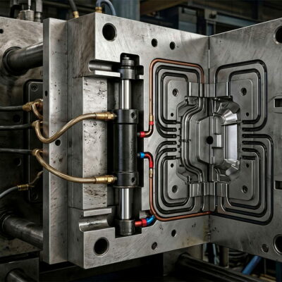
Hydraulic cylinders installed inside injection molds are designed to generate controlled linear forces along their axis. When the cylinder, the moving slide and the mold mechanism remain correctly aligned, the cylinder can operate reliably through a very large number of cycles.
However, when the cylinder is forced to compensate for a mechanical misalignment, the situation changes significantly.
A cylinder that is correctly sized for the required hydraulic force can still suffer premature failure if the mechanical system applies lateral or bending loads to the rod and cartridge.
A technical investigation performed by the Vega Technical Department illustrates this problem particularly well. The customer reported a broken hydraulic cylinder and requested an opinion based on photographs of the damaged component. Vega identified misalignment between the cylinder and the slide, or an incorrect mold movement, as the principal possible causes.
This article explains how this type of failure can develop and why correct mechanical alignment is just as important as correct hydraulic-cylinder sizing.
1. A Hydraulic Cylinder Is Designed to Work Along Its Axis
The fundamental function of a hydraulic cylinder is to convert hydraulic pressure into linear mechanical force.
Ideally, the force generated by the cylinder acts along its longitudinal axis.
The simplified operating principle is:
hydraulic pressure
↓
piston force
↓
rod movement
↓
movement of the mold component
The cylinder should therefore be installed so that the moving load follows the same axis as the cylinder rod.
When this condition is maintained, the rod primarily experiences axial loads.
The problem begins when the mechanism attempts to move in a direction that is not perfectly compatible with the cylinder axis.
This can happen even when the hydraulic pressure, cylinder bore and stroke are all correctly specified.
2. What Happens When the Cylinder and Slide Are Not Aligned?
According to the Vega Technical Department’s analysis, the type of crack observed could occur when there is imperfect axial alignment between the cylinder and the slide, or when the mold movement is incorrect.
This is an important distinction.
The cylinder may be perfectly manufactured and correctly dimensioned, but the mold mechanism can nevertheless impose abnormal mechanical loads on it.
Instead of acting purely along the cylinder axis, the load can generate a bending component.
The cylinder is then subjected to a combination of:
- axial force;
- lateral force;
- bending moment;
- repeated cyclic stress.
The longer the system operates under these conditions, the greater the possibility of fatigue damage.
3. Why Misalignment Can Bend the Rod
Consider a cylinder connected to a moving slide.
If the slide moves exactly parallel to the cylinder axis, the rod is essentially loaded axially.
If the slide moves at an angle, however, the connection forces the rod to follow a path that is not perfectly aligned with the cylinder.
The resulting force can be separated conceptually into:
axial component
and
lateral component
The lateral component creates bending.
Even a relatively small lateral force can become important when it is repeated thousands or millions of times.
This is why hydraulic-cylinder installation should always be considered as part of the complete mechanical design rather than as an isolated component.
4. The Specific Mounting Configuration Can Increase the Risk
The cylinder examined in this application had rear oil-delivery ports and was fixed to the mold using four longitudinal screws inserted from the top toward the bottom.
This mounting arrangement is particularly relevant to the technical analysis.
If the cylinder and the moving slide are not perfectly aligned, the rigid mounting can prevent the cylinder from naturally accommodating the misalignment.
Instead, the mechanical error can be transferred directly into the cylinder structure.
The result can be:
mold misalignment
↓
mechanical constraint
↓
rod bending
↓
additional stress on the cartridge
↓
cyclic fatigue
↓
crack or fracture
This sequence is consistent with the explanation provided by the Vega Technical Department.
5. Why the Rod Can Bend Even Though the Cylinder Is Hydraulic
It is sometimes assumed that hydraulic pressure is the main source of stress in a hydraulic cylinder.
In reality, hydraulic pressure is only one part of the overall mechanical loading.
A cylinder installed in an injection mold is also affected by the mechanical system connected to it.
For example, the mold may contain:
- slides;
- cores;
- guide systems;
- mechanical stops;
- plates;
- linkages;
- moving inserts.
If one of these components is not correctly aligned, the cylinder can become the element that absorbs the resulting mechanical error.
The hydraulic cylinder then acts as an unintended structural compensator.
This is not the function for which the cylinder is designed.
6. Axial Force Versus Bending Force
A useful way to understand the problem is to distinguish between axial and lateral loading.
Axial loading
The force acts along the cylinder axis.
This is the normal direction in which the cylinder is designed to generate force.
Lateral loading
The force acts perpendicular to the cylinder axis.
This produces bending and additional loads on:
- piston rod;
- guide system;
- cartridge;
- seals;
- mounting points.
When lateral loading is repeated during every mold cycle, the resulting stress can become a fatigue problem.
7. Why Fatigue Is Particularly Important in Injection Molds
Injection molds can operate for very large numbers of cycles.
A small mechanical error that causes only limited damage during one cycle can become a serious problem when repeated continuously.
For example:
1 cycle → small additional stress
10,000 cycles → repeated stress
100,000 cycles → progressive fatigue
1,000,000 cycles → potentially critical damage
The exact fatigue life cannot be established from the available technical documentation alone. However, Vega explicitly identified the possibility of a fatigue break occurring over time as a consequence of rod and cartridge bending caused by misalignment.
This is why alignment problems should be corrected rather than simply replacing the failed cylinder.
8. A Broken Cylinder Does Not Necessarily Mean a Defective Cylinder
When a cylinder breaks, the first reaction is often:
“The cylinder failed.”
But this statement does not identify the actual cause.
The failed component may simply be the component that ultimately absorbed an abnormal load generated elsewhere in the system.
This distinction is extremely important in mold engineering.
A damaged hydraulic cylinder can be the consequence of:
- incorrect mold alignment;
- incorrect slide movement;
- mechanical interference;
- excessive lateral load;
- incorrect installation;
- deformation of the mold structure.
The Vega Technical Department therefore stated that, without physically analyzing the cylinder and the mold drawing, it could not provide a definitive diagnosis.
That is an important engineering principle:
A photograph of the broken component can indicate a probable failure mechanism, but it does not necessarily identify the root cause.
9. Why the Mold Movement Must Be Checked
The Vega analysis specifically mentions not only cylinder/slide axiality but also wrong movement of the mold.
This means that troubleshooting should not stop at the cylinder mounting.
The complete movement must be checked.
Questions should include:
- Does the slide move parallel to the cylinder axis?
- Is the slide properly guided?
- Is there excessive play?
- Is there mechanical interference?
- Does the slide reach its end position correctly?
- Are there mechanical stops?
- Does the cylinder begin moving before the mechanism is free?
- Does the mold movement force the rod in a direction different from its intended axis?
A cylinder can only operate correctly if the mechanism it drives also moves correctly.
10. Guide Systems Are Essential
The cylinder should not be expected to guide the slide.
The mold mechanism itself should provide the necessary guidance.
The hydraulic cylinder should primarily provide the required force and movement.
If the cylinder is forced to guide a poorly supported slide, lateral forces can be transferred to the rod.
This can result in:
- increased friction;
- rod bending;
- guide wear;
- seal wear;
- abnormal cartridge loading;
- fatigue damage.
The same engineering principle is emphasized in Vega’s current technical material: hydraulic cylinders should remain correctly aligned throughout their stroke, while the mechanical system should provide appropriate guidance.
11. Why the Mounting Design Matters
The cylinder mounting arrangement determines how mechanical forces are transferred between the mold and the cylinder.
A rigid mounting can be perfectly appropriate when:
- the cylinder axis is correctly aligned;
- the slide is correctly guided;
- the mold structure is sufficiently rigid;
- the movement remains linear.
However, if the mold mechanism contains an angular error, a rigid mounting can transmit that error directly into the cylinder.
Therefore, during mold design, engineers should verify:
- mounting-surface accuracy;
- parallelism;
- coaxiality;
- slide alignment;
- guide clearances;
- stroke alignment.
12. The Role of the Four Longitudinal Screws
The cylinder in this application was fixed using four longitudinal screws passing through the cylinder mounting structure.
The important point is not that four screws are inherently problematic.
Rather, the complete mounting configuration must be considered together with the alignment of the mold mechanism.
If the cylinder is rigidly fixed and the slide cannot move exactly along the cylinder axis, the resulting forces can be transmitted to the cylinder.
Therefore:
rigid mounting + misaligned mechanism
can produce:
additional bending stress on the cylinder.
The number of fixing screws alone does not determine whether the installation is correct.
13. What Should Be Checked After a Cylinder Breaks?
When a cylinder breaks unexpectedly, replacing it immediately may restore production temporarily but does not necessarily solve the problem.
A proper investigation should examine the complete application.
Cylinder
Check:
- fracture location;
- rod condition;
- cartridge condition;
- guide wear;
- seal condition;
- evidence of bending;
- abnormal marks.
Mold
Check:
- cylinder mounting;
- slide alignment;
- guide systems;
- mold plates;
- mechanical stops;
- possible interference.
Movement
Check:
- complete stroke;
- movement direction;
- synchronization;
- end positions;
- possible mechanical blockage.
Hydraulic system
Check:
- operating pressure;
- pressure peaks;
- flow;
- valve operation;
- hydraulic timing.
However, the available Vega documentation for this particular application does not provide measurements or test results for these additional factors, so they should be treated as investigation points rather than as confirmed causes.
14. Why Replacing the Cylinder May Not Solve the Problem
Suppose the original cylinder fails because of misalignment.
If the damaged cylinder is simply replaced with a new identical cylinder, the new component will be exposed to the same mechanical conditions.
The sequence can therefore repeat:
new cylinder installed
↓
same mold alignment
↓
same lateral load
↓
same rod/cartridge bending
↓
new fatigue damage
↓
another failure
This is why root-cause analysis is more valuable than simply replacing the failed component.
15. How to Prevent Misalignment-Related Failures
The most effective solution is to prevent abnormal loads from reaching the hydraulic cylinder.
The mold designer should verify:
1. Cylinder axis
The cylinder axis must correspond to the intended direction of slide movement.
2. Slide guidance
The slide must be adequately guided independently of the hydraulic cylinder.
3. Mounting surfaces
The cylinder mounting surfaces should be accurately machined and correctly positioned.
4. Complete stroke
Alignment should be checked throughout the entire cylinder stroke, not only at one position.
5. Mechanical interference
The slide should not encounter unexpected resistance during movement.
6. Mold movement
The mold must follow the intended opening and closing sequence without forcing the cylinder into an abnormal position.
These principles are consistent with Vega’s broader technical guidance on hydraulic-cylinder misalignment and side loading.
16. Alignment Must Be Checked Throughout the Stroke
A common mistake is checking alignment only when the mold is closed.
A cylinder can appear perfectly aligned at one position and become misaligned as the slide moves.
Therefore, alignment should be evaluated throughout the complete operating stroke.
The important question is not:
“Is the cylinder aligned at the starting position?”
but:
“Does the load remain aligned with the cylinder axis throughout the entire movement?”
This is particularly important for long strokes and complex mold mechanisms.
17. The Difference Between Hydraulic and Mechanical Problems
A hydraulic cylinder can appear to have a mechanical failure even though the hydraulic system itself is functioning correctly.
For example:
Hydraulic problem
- excessive pressure;
- pressure spikes;
- incorrect hydraulic circuit;
- incorrect valve operation.
Mechanical problem
- misalignment;
- lateral loading;
- incorrect slide movement;
- mechanical interference;
- insufficient guidance.
The application discussed here points primarily toward a mechanical alignment/movement issue, rather than identifying a hydraulic-pressure problem.
This distinction is important during troubleshooting.
18. Why the Technical Department Cannot Diagnose Every Failure From Photographs
The original customer communication contained photographs of the broken cylinder and asked Vega for an opinion.
Vega’s response was appropriately cautious.
The Technical Department explained that the proposed explanation was based on the visible failure mechanism but stated that a definitive analysis would require:
- inspection of the cylinder;
- the mold drawing.
This is a good example of professional failure analysis.
An engineer should distinguish between:
probable cause
and
confirmed root cause.
Without examining the failed component and the mechanical installation, it is not appropriate to state with certainty that the cylinder itself was defective.
19. A Practical Troubleshooting Procedure
When a hydraulic cylinder in an injection mold breaks, follow this sequence.
Step 1 — Stop and document the failure
Record:
- cylinder position;
- mold position;
- production cycle;
- visible damage;
- hydraulic conditions.
Step 2 — Inspect the cylinder
Look for:
- cracks;
- fractures;
- bending;
- scoring;
- abnormal wear.
Step 3 — Inspect the slide
Verify:
- guides;
- movement;
- clearances;
- possible interference.
Step 4 — Check alignment
Verify the relationship between:
cylinder axis ↔ slide axis
throughout the complete stroke.
Step 5 — Check mold movement
Determine whether the mold could have forced the cylinder into an abnormal position.
Step 6 — Inspect the mounting
Check:
- mounting surfaces;
- fixing screws;
- positioning;
- parallelism;
- mechanical rigidity.
Step 7 — Inspect the hydraulic circuit
Only after the mechanical installation has been evaluated should hydraulic pressure, flow and timing be considered as possible contributors.
Step 8 — Determine the root cause
Do not simply replace the cylinder until the failure mechanism has been understood.
20. The Most Important Engineering Lesson
A hydraulic cylinder should generate force.
It should not compensate for errors in the mechanical design of the mold.
When a cylinder is forced to move a misaligned slide, the rod and cartridge can be exposed to bending forces that are very different from the intended axial load.
In the application analyzed by Vega, the Technical Department specifically identified possible lack of axiality between the cylinder and slide or incorrect mold movement, with the possibility of rod and cartridge bending followed over time by fatigue failure.
The correct approach is therefore to investigate the complete mechanical system.
21. Final Checklist for Mold Designers
Before commissioning a hydraulic cylinder inside an injection mold, verify:
Cylinder installation
- Correct mounting
- Correct cylinder axis
- Accurate mounting surfaces
- Correct fixing
Slide
- Correct guidance
- No excessive play
- No mechanical interference
- Correct movement direction
Alignment
- Cylinder and slide are axially aligned
- Alignment remains correct throughout the complete stroke
- No lateral loads are transferred to the rod
Mold movement
- Opening and closing sequence is correct
- No abnormal mechanical force is generated
- Cylinder is not forced to follow an incorrect trajectory
Failure investigation
- Inspect the fracture
- Inspect the rod
- Inspect the cartridge
- Inspect the slide
- Inspect the guides
- Check the mold drawing
- Check hydraulic conditions
Conclusion
A broken hydraulic cylinder inside an injection mold is not necessarily evidence of a defective cylinder.
In many situations, the cylinder may be the component that ultimately fails because it has been subjected to abnormal mechanical forces generated elsewhere in the mold.
The Vega Technical Department identified two important possible causes in the analyzed application:
imperfect axial alignment between the cylinder and slide
and
incorrect mold movement.
Because the cylinder had rear oil ports and was rigidly fixed to the mold through four longitudinal screws, a misalignment could cause bending of the rod and cartridge, potentially leading to a fatigue fracture over time.
The key lesson is simple:
A hydraulic cylinder cannot correct an incorrectly designed or misaligned mold mechanism. The cylinder must be correctly aligned with the load, while the mold’s guide system must control the movement.
When a cylinder breaks, therefore, the correct question is not simply:
“Why did the cylinder break?”
but:
“What mechanical condition forced the cylinder to operate outside its intended axial load?”
That question is often the starting point for finding the real root cause.
Useful Vega References
These official Vega resources are particularly relevant to this subject:
- Hydraulic Cylinder Misalignment: The Hidden Cause of Broken Rods — detailed Vega technical article on misalignment, side loads, rod scoring and fatigue.
- Why Hydraulic Cylinder Seals Wear Prematurely Even When Temperature Is Not the Problem — useful reference on misalignment, side loads and premature wear.
- Technical Analysis of a Hydraulic Cylinder After Over 1 Million Cycles — analysis of long-term cylinder failure and the importance of correct installation and loading.
- Hydraulic Cylinders for Injection Molds – Vega Cylinders — official Vega product range for plastic injection molding and die-casting applications.
- Vega Cylinders – Hydraulic Cylinders for Injection Molds — official Italian Vega website for hydraulic cylinders designed for injection molds and die casting.