Introduction
Injection mold slide force calculation is one of the most important aspects of hydraulic cylinder sizing for injection molds. However, even experienced mold designers can occasionally make a subtle mistake that completely changes the final cylinder selection.
A recent engineering project analyzed by the Vega Technical Department perfectly demonstrates this principle.
A customer developing a polypropylene injection mold requested validation of the hydraulic cylinder sizing for a side-action slide mechanism operating under an estimated cavity pressure of 450 bar. The customer had already performed a detailed calculation of both injection and extraction forces and proposed two possible hydraulic cylinder solutions.
After reviewing the calculations, the Vega Technical Department identified a critical mathematical inconsistency:
the slide angle had been correctly considered for the extraction force calculation, but not for the injection force calculation.
This apparently minor oversight changed the entire hydraulic cylinder sizing process.
This case demonstrates one of the most important principles in injection mold engineering:
If geometry transforms one force, it transforms all forces.
The Initial Design Conditions
The mold was designed for molding a component in:
Polypropylene (PP)
with an estimated material shrinkage of:
1.4%.
The slide geometry presented the following characteristics:
| Parameter | Value |
|---|---|
| Plastic material | PP |
| Estimated cavity pressure | 450 bar |
| Projected frontal area | 45.357 cm² |
| Lateral contact area | 91.87 cm² |
| Slide angle | 36° |
The customer had already developed a complete force calculation model and requested confirmation of the selected hydraulic cylinders.
At first glance, the methodology appeared correct.
However, a closer analysis revealed an important inconsistency.
Injection Mold Slide Force Calculation Begins with Pressure
The first step in every injection mold slide force calculation consists of converting cavity pressure into mechanical force.
The fundamental relationship is:
where:
- F = generated force;
- P = cavity pressure;
- A = projected frontal area.
Substituting the actual values:
F = 450 × 45.357
which produces:
F = 20,410.65 kgf.
The customer correctly calculated the total force generated by the plastic pressure.
However, this force does not act directly on the hydraulic cylinder.
Why Slide Geometry Changes Everything
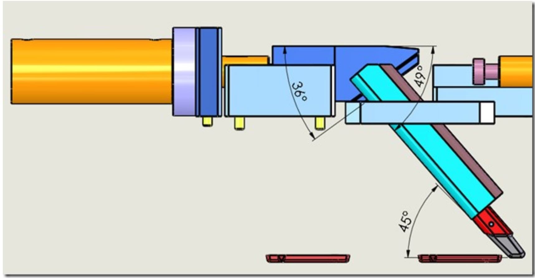
The slide mechanism operated with a working angle of:
36°
As in all inclined slide systems, the force generated by the cavity pressure must be transformed according to the slide geometry.
The force transmitted to the hydraulic cylinder can be expressed as:
where:
- Fcylinder = force acting on the cylinder;
- Finjection = force generated by cavity pressure;
- α = slide angle.
For this project:
tan(36°) ≈ 0.72654
Therefore:
Fcylinder = 20,410.65 × 0.72654
resulting in:
Fcylinder ≈ 14,829 kgf.
This calculation immediately reduced the effective cylinder load by almost 30%.
The Critical Engineering Mistake
The customer had correctly applied the slide angle correction to the extraction force calculation.
However, the same transformation had not been applied to the injection force calculation.
This is one of the most common mistakes in injection mold engineering.
Many designers unconsciously assume that:
- extraction forces depend on geometry;
- injection forces act directly.
In reality, both forces travel through exactly the same mechanical system.
Consequently:
if the slide angle modifies one force, it must also modify the other.
The Vega Technical Department immediately identified this inconsistency and corrected the entire calculation model.
Understanding Push Force Versus Pull Force
One of the most important lessons from this project is that injection mold slides operate under two completely different loading conditions.
Push Force
Push force is generated by:
- cavity pressure;
- melt pressure peaks;
- packing pressure;
- pressure amplification effects.
This force attempts to move the slide backwards during injection.
Pull Force
Pull force is generated by:
- plastic shrinkage;
- adhesion between plastic and steel;
- friction;
- thermal contraction effects.
This force acts during mold opening and extraction.
These two forces often differ by an order of magnitude.
Calculating the Plastic Adhesion Force
The customer estimated the plastic adhesion force using the standard engineering approach:
where:
- A = lateral contact area;
- K = plastic adhesion coefficient.
For polypropylene:
K = 15 kg/cm²
was adopted.
Using the measured contact surface:
A = 91.87 cm²
the extraction force became:
Ftraction = 91.87 × 15
which gives:
Ftraction ≈ 1,378 kgf.
This value does not include frictional effects.
Why Friction Cannot Be Ignored
The theoretical extraction force rarely represents the actual operating load.
The real force required to move the slide also depends on:
- guide friction;
- lubrication conditions;
- surface roughness;
- thermal expansion;
- elastic deformation;
- wear;
- manufacturing tolerances;
- assembly conditions.
For this reason, hydraulic cylinder sizing should never rely exclusively on theoretical calculations.
A sufficient safety margin must always be included.
Selecting the Hydraulic Cylinder
After correcting the force transformation model, the Vega Technical Department proposed two possible solutions:
| Cylinder | Operating Pressure |
|---|---|
| CG056 | 130 bar |
| CG071 | 71 bar |
Both solutions guaranteed:
- adequate safety factors;
- compensation of friction effects;
- tolerance to process variations;
- long-term operational reliability.
The final selection could therefore be based on:
- available installation space;
- hydraulic system pressure;
- customer preferences;
- required safety margins.
Why Force Transformation Is More Important Than Force Calculation
This project demonstrates one of the most important principles of mold engineering.
The customer’s calculations were almost entirely correct.
The only error was forgetting that the slide angle transforms every force transmitted through the mechanism.
This distinction separates:
- engineers who apply formulas;
- engineers who understand force transmission.
Because in mold engineering:
the challenge is not calculating the force.
The challenge is understanding where the force actually goes.
Lessons Learned
1. Injection mold slide force calculation always depends on geometry.
2. Slide angles transform both push and pull forces.
3. Cavity pressure never acts directly on inclined slides.
4. Plastic adhesion forces are usually much smaller than injection forces.
5. Friction effects cannot be predicted accurately.
6. Hydraulic cylinders should always include a safety margin.
7. Understanding force transmission is more important than solving equations.
Conclusion
At first glance, this project appeared to be a standard hydraulic cylinder sizing exercise.
However, the detailed analysis performed by the Vega Technical Department demonstrated that a single missing trigonometric transformation was sufficient to alter the entire engineering solution.
By correcting the force transmission model and validating the complete methodology, the Vega Technical Department confirmed one of the most important principles of injection mold engineering:
If geometry transforms one force, geometry transforms all forces.