Introduction
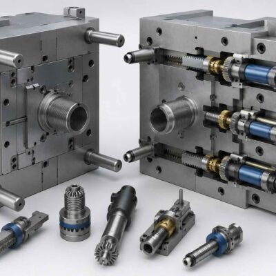
Injection mold slide force calculation is one of the most critical and misunderstood aspects of mold engineering. Although the mathematical equations used to calculate slide forces are relatively straightforward, the real challenge is understanding how those forces are actually transmitted through the mold geometry.
A recent project analyzed by the Vega Technical Department perfectly illustrates this principle.
A customer developing a complex ABS injection mold requested validation of the hydraulic cylinder sizing for two interconnected slide systems subjected to an estimated cavity pressure of 550 bar. The customer had already performed a complete force calculation and proposed a preliminary cylinder selection. However, the final engineering decision required a deeper analysis of how forces were actually transmitted through the mold geometry.
This project demonstrates one of the most important principles in injection mold engineering:
The force calculated from cavity pressure is not always the force that determines hydraulic cylinder sizing.
Sometimes, understanding the kinematics of the mold is more important than calculating the pressure itself.
The Initial Engineering Problem
The mold was designed for molding an ABS component with an estimated cavity pressure of:
P = 550 bar
The projected frontal area subjected to cavity pressure was estimated at:
A = 200 cm²
According to the fundamental hydraulic relationship:
F = P × A
the resulting force generated by the plastic pressure became:
F = 550 × 200
F = 110,000 kgf.
At first glance, the problem appeared simple:
determine how this force would affect the two slide mechanisms and select the appropriate hydraulic cylinders.
However, as often happens in mold engineering, the answer was not as straightforward as the mathematics initially suggested.
Injection Mold Slide Force Calculation Starts with Kinematics
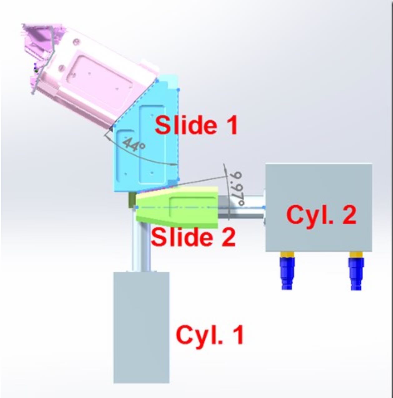
The mold contained two interconnected slide systems:
- Slide 1, acting as the primary locking mechanism;
- Slide 2, operating as a secondary moving element actuated by a separate hydraulic cylinder.
The critical observation made by the Vega Technical Department was that the two slides performed completely different mechanical functions.
Although both were subjected to the same cavity pressure, the force transmission mechanism was entirely different.
This distinction changed the entire cylinder sizing philosophy.
Slide 1: A Classical Force Transformation Problem
The primary slide was designed with a working angle of:
α₁ = 44°
The customer correctly applied the standard slide force transformation equation:
Fcyl = Finj × tan(α)
where:
- Fcyl = force acting on the hydraulic cylinder;
- Finj = force generated by cavity pressure;
- α = slide angle.
Substituting the values:
Fcyl₁ = 110,000 × tan(44°)
Since:
tan(44°) ≈ 0.9657
the resulting cylinder force became:
Fcyl₁ ≈ 106,227 kgf.
This result immediately reveals an important aspect of slide geometry.
At large slide angles, the mechanical advantage decreases significantly.
In this case, the cylinder force becomes almost equal to the total injection force.
Therefore, the hydraulic cylinder must behave primarily as a mechanical locking device.
For this reason, the customer proposed:
CM080 with Ø36 rod operating at 105 bar.
The Vega Technical Department confirmed this approach.
Slide 2: The Calculation Was Correct, But the Interpretation Was Wrong
The second slide presented a completely different geometry.
The slide angle was:
α₂ = 9.97°
Again, the customer correctly applied the trigonometric force equation:
Fcyl₂ = 110,000 × tan(9.97°)
Since:
tan(9.97°) ≈ 0.1758
the resulting force became:
Fcyl₂ ≈ 18,674 kgf.
At this point, a classical engineering mistake could have occurred.
A designer focusing exclusively on the calculated force might conclude:
“The cylinder must resist nearly 19 tons.”
However, this conclusion would have been incorrect.
Why Physics Changed the Answer
The key observation made by Vega Technical Department was that the geometry of Slide 2 prevented the injection pressure from generating a reverse movement of the slide.
This is one of the most misunderstood concepts in injection mold hydraulics.
A calculated force does not necessarily become an effective operating force.
The actual transmitted force depends on:
- force direction;
- kinematic constraints;
- friction conditions;
- geometric locking effects;
- force reaction paths;
- mechanical stability of the system.
In this specific case:
the calculated force existed mathematically but could not physically generate slide retraction.
Therefore, the cylinder did not require a holding force of 18,674 kgf.
Holding Force Versus Operating Force
This case demonstrates the fundamental distinction between two completely different engineering concepts.
Holding Force
Holding force represents the force required to prevent movement against an external load.
This force is typically generated by:
- injection pressure;
- cavity pressure peaks;
- hydraulic pressure spikes;
- external mechanical loads.
Operating Force
Operating force represents the force required to move the mechanism under real operating conditions.
This force must overcome:
- sliding friction;
- guide friction;
- seal friction;
- elastic deformation;
- thermal expansion;
- wear conditions;
- manufacturing tolerances.
The Vega Technical Department recognized that Cylinder 2 belonged to the second category.
The Force Nobody Can Calculate
The customer estimated the plastic adhesion force using:
A = 285 cm²
and an adhesion coefficient for ABS of:
K = 15 kg/cm²
Thus:
Ftraction = A × K
which gives:
Ftraction = 285 × 15
Ftraction = 4,275 kgf.
However, this value represents only part of the total force.
The real operating force also includes several factors that cannot be accurately predicted analytically:
- surface finish effects;
- lubrication conditions;
- wear;
- thermal deformation;
- guide alignment;
- assembly tolerances;
- pressure fluctuations;
- dynamic acceleration loads.
These effects often dominate the actual cylinder load.
Why Reserve Force Is Essential
The Vega Technical Department correctly identified that the purpose of Cylinder 2 was not to resist cavity pressure but to provide sufficient reserve traction force to overcome all unknown friction effects.
This is a classical hydraulic engineering principle:
When friction cannot be calculated reliably, it must be compensated with force reserve.
Consequently, Vega Technical Department suggested considering:
- CM080, or
- CM100
not because the cylinder had to resist injection pressure, but because it had to guarantee reliable operation under all production conditions.
Why Small Slide Angles Are Dangerous
The force transformation relationship:
F = F₀ × tan(α)
shows that:
| Angle | tan(α) |
|---|---|
| 5° | 0.087 |
| 10° | 0.176 |
| 20° | 0.364 |
| 30° | 0.577 |
| 44° | 0.966 |
This explains why the 9.97° slide behaved completely differently from the 44° slide.
Small angles may generate:
- partial self-locking effects;
- high friction sensitivity;
- strong dependence on manufacturing tolerances;
- non-linear force transmission behavior.
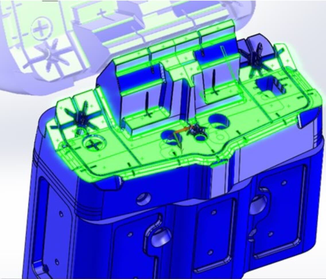
The Importance of 3D Kinematic Analysis
The most important lesson from this project is that force calculations alone are insufficient.
The complete 3D geometry of the mold must always be evaluated to understand:
- actual force directions;
- mechanical constraints;
- reaction forces;
- locking conditions;
- friction generation mechanisms;
- potential self-locking effects.
Without understanding the kinematics of the mold, even perfectly correct calculations may lead to incorrect engineering decisions.
Lessons Learned
1. Correct calculations do not always lead to the correct cylinder.
2. Injection pressure force and operating force are not the same thing.
3. Mold kinematics often dominate hydraulic calculations.
4. Small slide angles can generate self-locking conditions.
5. Friction forces cannot always be calculated accurately.
6. Safety margins are often more important than theoretical precision.
7. Understanding force transmission is more important than calculating force itself.
Conclusion
At first glance, this project appeared to be a conventional hydraulic cylinder sizing exercise.
In reality, it became an exercise in understanding how forces truly propagate inside an injection mold.
The customer’s calculations were mathematically correct.
However, the final engineering solution required a deeper understanding of:
- slide kinematics;
- mechanical constraints;
- friction behavior;
- force transmission paths;
- geometric locking conditions.
By recognizing that Cylinder 2 did not need to resist cavity pressure directly, but only required sufficient reserve force to guarantee reliable operation, the Vega Technical Department demonstrated one of the most valuable principles of engineering:
Engineering is not about calculating forces.
Engineering is about understanding which forces actually matter.