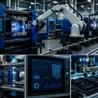
In plastic injection molds, hydraulic cylinders are often used to move and hold slides, punches, cores and other mold components in position during the injection phase.
When a mold component moves backwards during injection, the immediate assumption is often that the hydraulic cylinder is not strong enough.
But this is not necessarily the case.
A hydraulic cylinder that appears to “lose its position” can be affected by several different factors, including:
- cylinder sizing;
- preload;
- hydraulic pressure;
- check-valve installation;
- hydraulic circuit configuration;
- mechanical tolerances;
- elastic deformation;
- injection conditions;
- material being processed.
A real technical case analysed by the Vega Team demonstrates why these factors must be investigated together.
The Customer reported that the cylinders initially worked correctly, but after several cycles one cylinder with a 10 mm stroke began to retract slightly. When the material was changed from PP to ABS, the problem became significantly worse.
The investigation therefore required much more than simply replacing the cylinders or their fixing components.
The Problem: The Cylinder Slowly Retracts During Injection
During the initial mold trials with PP, the hydraulic cylinders appeared to operate correctly.
After some production cycles, however, the cylinder with a 10 mm stroke began to move backwards slightly.
The phenomenon became considerably worse when the Customer changed from PP to ABS.
The movement was not only a mechanical concern.
The Customer also observed an increase in flash on the molded component and suspected that the movement of the cylinders was contributing to the problem.
This created a typical injection-molding engineering challenge:
Was the cylinder actually failing to lock, or was something else in the hydraulic and mechanical system causing the movement?
The First Question: Is the Cylinder Correctly Sized?
When a cylinder moves backwards under injection pressure, the first parameter to verify is the force available from the cylinder and its locking system.
The Vega Team therefore checked the cylinder calculation again.
The conclusion was that the cylinders were correctly dimensioned and that, under the expected conditions, they should lock.
This is an important distinction.
A cylinder can be correctly sized according to the calculated forces and still show unexpected behaviour in a real mold if other conditions are not correct.
Therefore:
correct cylinder sizing does not automatically guarantee correct system behaviour.
The investigation had to continue.
Replacing the Fixing Flanges Did Not Solve the Problem
The Customer had already requested new fixing flanges after observing movement of the cylinders.
However, the Vega Team noted that all cylinders had been changed together with their fixing flanges, while the result remained the same.
This was an important diagnostic indication.
If replacing the fixing components does not eliminate the movement, the flange itself becomes a less likely explanation for the entire phenomenon.
The investigation therefore moved towards the conditions under which the self-locking system was operating.
Preload Became a Key Parameter
One of the first parameters the Vega Team wanted to verify was the preload.
Preload is particularly important in applications where a hydraulic cylinder must keep a mold component firmly against a mechanical reference during injection.
The purpose of preload is not simply to increase the nominal hydraulic force.
It establishes the mechanical condition required for the mold component to remain properly positioned before injection.
In the case analysed here, the Vega Team specifically asked whether the preload was correct.
This was not an arbitrary question.
The previous tests had already shown that reducing the preload affected the measured movement of the system.
Measuring the Movement with a Comparator
One of the most interesting aspects of this technical investigation was the use of a comparator to measure the actual cylinder movement.
After reducing the preload, the measured movement had been approximately 0.02 mm.
This measurement was important because the movement was small enough that visual observation alone could easily be misleading.
In precision injection molding, a movement of a few hundredths of a millimeter can be enough to affect the final result.
The Vega Team therefore requested that the Customer repeat the comparator measurement before proceeding with the replacement of the flanges.
This is a useful general diagnostic principle:
measure the actual movement before deciding which component must be replaced.
Why a Comparator Is More Useful Than Visual Inspection
A cylinder that moves by a fraction of a millimeter may appear stable to the naked eye.
A comparator, on the other hand, can reveal exactly how much movement is occurring.
This makes it possible to distinguish between:
- no movement;
- elastic deformation;
- a small controlled displacement;
- continuous retraction;
- a significant mechanical movement.
The measurement also allows the movement to be correlated with the quality of the molded part.
For example:
measured cylinder movement → mold opening → plastic infiltration → flash
This does not automatically prove a cause-and-effect relationship, but it provides a much stronger basis for technical analysis.
The Check Valve Must Be Correctly Installed
Another important element of the investigation was the check valve.
The Customer reported that a check valve was installed directly on each cylinder.
The presence of a check valve is intended to help prevent unwanted hydraulic movement by limiting the return flow of oil.
However, simply having a check valve in the circuit is not enough.
Its installation and behaviour must also be verified.
The Vega Team therefore asked explicitly whether the check valves were correctly installed.
This is particularly important in applications where the cylinder must maintain its position under the high forces generated during injection.
A Check Valve Is Not the Same as a Mechanical Lock
This case also highlights an important engineering distinction.
A check valve maintains hydraulic pressure by preventing or limiting oil from flowing backwards.
A mechanical locking system, on the other hand, creates a mechanical load path that resists external forces.
These are two different principles.
For injection-mold applications, this distinction becomes particularly important when the mold component is subjected to substantial cavity pressure.
Vega’s technical documentation describes self-locking cylinders as solutions designed to move and mechanically lock mold components that must withstand injection pressure.
Vega V270CG Self-Locking Hydraulic Cylinders
The Hydraulic Pressure During Injection Is Critical
The most interesting part of the case concerns the hydraulic pressure during the injection phase.
The Vega Team asked the Customer to verify whether the hydraulic pressure was being stopped before the injection started, rather than being interrupted at the same time as injection.
This timing can be critical.
A self-locking hydraulic system may require specific hydraulic conditions to ensure that the locking mechanism remains correctly engaged.
The Customer had tried stopping the hydraulic pressure during injection.
Surprisingly, the result was worse.
The Customer reported that the mold actually worked better when hydraulic pressure was maintained during injection, even though a check valve was installed directly on each cylinder.
This observation was an important clue.
Why Maintaining Pressure Can Matter
The behaviour observed in this case illustrates an important principle:
the hydraulic circuit can be part of the locking system.
The mechanical locking mechanism and hydraulic circuit cannot always be analysed independently.
Vega’s technical material on self-locking cylinders explains that hydraulic pressure may need to be maintained during the injection phase to ensure correct locking performance; when continuous pressure cannot be maintained, a suitable pilot-operated check valve may be required close to the cylinder.
Preload in Self-Locking Hydraulic Cylinders
Why Hydraulic Self-Locking Cylinders Move During Injection
This is consistent with the field observation in the case: removing hydraulic pressure during injection did not improve the situation.
Why the Material Change from PP to ABS Was Significant
Another important detail was the change in processing material.
With PP, the cylinders initially worked correctly.
After some cycles, one cylinder began to retract slightly.
When the Customer changed to ABS, the result became much worse.
This does not prove that ABS was the cause.
Instead, it indicates that the behaviour of the complete mold system was sensitive to the processing conditions.
Different materials can require different injection conditions, and these conditions can modify the forces acting on mold components.
Therefore, when investigating unexpected cylinder movement, it is useful to record:
- material;
- injection pressure;
- injection speed;
- holding pressure;
- cycle conditions;
- mold temperature;
- observed flash;
- cylinder position.
A comparison between materials can provide valuable diagnostic information.
Flash Can Be an Indication of Mold Movement
The Customer also reported flash on the plastic component.
The Vega Team asked about the magnitude of the flash and specifically whether it was approximately 0.1 mm.
Flash is not necessarily proof that a hydraulic cylinder has moved.
However, when flash appears together with a measured movement of the mold mechanism, the two phenomena should be investigated together.
A small movement can create a clearance through which molten plastic can penetrate.
This is one of the reasons preload can be important in self-locking hydraulic-cylinder applications.
Vega’s technical documentation explains that preload is used to compensate for small clearances and elastic deformation and to improve contact between mold components before injection.
Why Hydraulic Cylinder Preload Improves Mold Quality
The Cylinder Was Not Necessarily the Problem
At this stage, an important conclusion can already be drawn.
The available documentation does not establish that the hydraulic cylinder itself was defective.
On the contrary, the Vega Team had rechecked the calculation and considered the cylinders correctly dimensioned.
The investigation instead focused on the conditions required for the cylinder to maintain the mold component in position:
- correct preload;
- correct check-valve installation;
- hydraulic pressure during injection;
- actual cylinder movement;
- mechanical fixing;
- process conditions.
This is a much more useful way to approach a complex mold problem.
Why Replacing Components Too Early Can Be Misleading
If a cylinder moves, it can be tempting to replace it immediately.
If the problem remains, the next component may be replaced.
This can quickly become an expensive trial-and-error process.
The approach documented in this case was different.
Before replacing additional components, the Vega Team asked the Customer to repeat the measurement with a comparator and verify the preload and check-valve configuration.
This allows the investigation to distinguish between:
component failure
and
system behaviour.
That distinction is particularly important when several components have already been replaced without changing the result.
A Systematic Diagnostic Procedure
When a self-locking hydraulic cylinder retracts during injection, a structured diagnostic sequence can help.
1. Check the cylinder sizing
Verify that the cylinder has sufficient force and locking capacity for the actual application.
2. Verify the preload
Confirm that the preload is within the required range and has been correctly adjusted.
3. Measure the actual movement
Use a comparator instead of relying on visual inspection.
4. Check the fixing system
Verify the flanges, mechanical stops and connections.
5. Check the valve
Confirm that the check valve is the correct type and correctly installed.
6. Analyse hydraulic pressure
Measure the pressure actually available at the cylinder during injection.
7. Check the pressure sequence
Determine exactly when hydraulic pressure is maintained or released in relation to injection.
8. Compare process conditions
If the problem changes when the material or process conditions change, investigate the resulting differences in injection load.
9. Correlate movement with flash
Measure both the cylinder movement and the resulting flash to establish whether the two phenomena are related.
10. Replace components only after the diagnosis
Once the failure mechanism is understood, the appropriate corrective action can be selected.
The Importance of Hydraulic Circuit Design
The hydraulic circuit should be considered part of the cylinder application.
A self-locking cylinder can have the correct mechanical characteristics, but its behaviour may still be affected by the way pressure is supplied and maintained.
Relevant parameters include:
- pressure stability;
- pressure at the cylinder;
- check-valve position;
- hose length;
- trapped air;
- oil compressibility;
- pressure losses.
Vega’s current technical guidance specifically highlights the importance of maintaining hydraulic pressure during injection and, where necessary, using a pilot-operated check valve close to the cylinder.
Why the Problem Appeared Only After Several Cycles
Another interesting point is that the mold initially worked correctly with PP and only after several cycles did the cylinder begin to retract.
This makes the problem more difficult to diagnose.
A system that works during the first few cycles but changes behaviour later may require investigation of:
- preload stability;
- mechanical settling;
- thermal effects;
- changes in process conditions;
- pressure behaviour;
- elastic deformation;
- gradual changes in the mold mechanism.
The case documentation does not establish which of these factors caused the time-dependent behaviour.
Therefore, it would be incorrect to assign a single definitive cause based only on the available correspondence.
The important lesson is instead that a delayed failure requires measurements under real production conditions.
What This Customer Case Teaches
Several practical lessons can be taken from this case.
Correct sizing is only the starting point
The cylinders were checked and considered correctly dimensioned, yet the system still required further investigation.
Preload must be verified
The correct preload can be critical to the behaviour of a self-locking system.
A check valve must be correctly integrated
Installing a check valve directly on the cylinder does not eliminate the need to verify its installation and hydraulic behaviour.
Hydraulic pressure can be part of the solution
The field test showed that stopping the hydraulic pressure during injection made the result worse.
Small movements should be measured
The comparator measurement of approximately 0.02 mm after preload reduction demonstrates why precision measurement is important.
Different materials can expose different behaviour
The problem became significantly worse when the Customer changed from PP to ABS.
Self-Locking Hydraulic Cylinders for Injection Molds
Self-locking hydraulic cylinders are specifically designed for applications where a mold component must be moved and then held securely against the forces generated during injection.
Vega’s V270CG, for example, is a self-locking hydraulic cylinder designed for moving and locking mold components such as slides, pins and plugs. The manufacturer also describes preload adjustment as a way of improving the stability of the mold component under injection pressure.
V270CG Self-Locking Hydraulic Cylinders
The broader Vega range for molds includes dedicated hydraulic-cylinder families for different applications, including mechanical-locking cylinders.
Conclusion
When a hydraulic cylinder retracts during injection, it is tempting to conclude that the cylinder is defective or incorrectly sized.
This case shows why that conclusion can be premature.
The cylinders had been checked and were considered correctly dimensioned. Fixing flanges had been changed, but the problem remained. The Customer was using check valves directly on the cylinders, yet the mold performed worse when hydraulic pressure was stopped during injection.
The investigation therefore focused on the complete system:
cylinder sizing → preload → mechanical fixing → check valve → hydraulic pressure → injection conditions → measured movement.
The case also showed why a comparator measurement is essential when the suspected movement is very small. A movement of approximately 0.02 mm had been observed after reducing the preload.
Most importantly, the available documentation does not demonstrate a single definitive root cause.
Instead, it demonstrates an engineering approach:
measure first, verify the hydraulic and mechanical conditions, and only then replace components.
For injection-mold applications, reliable locking is not determined by the hydraulic cylinder alone. It depends on the correct interaction between the cylinder, preload, hydraulic circuit, check valve, mold mechanics and injection process.
Useful Vega Technical Resources
Self-Locking Hydraulic Cylinders
Official Vega information on self-locking technology, preload and applications in plastic injection molds.
Self-Locking Hydraulic Cylinders – Vega Cylinders
V270CG Self-Locking Hydraulic Cylinders
Product information for Vega’s self-locking hydraulic-cylinder range for mold applications.
V270CG Self-Locking Hydraulic Cylinders – Vega Cylinders
Preload in Self-Locking Hydraulic Cylinders
Technical article explaining the role of preload, hydraulic pressure and check valves in injection-mold applications.
Preload in Self-Locking Hydraulic Cylinders – iCVEGA
Why Hydraulic Self-Locking Cylinders Move During Injection
Technical article focused specifically on unwanted movement during injection and the role of hydraulic pressure.
Why Hydraulic Self-Locking Cylinders Move During Injection – iCVEGA
How to Select the Correct Self-Locking Hydraulic Cylinder for an Injection Mold
Engineering guidance covering cylinder sizing, preload, locking capacity and hydraulic load holding.
How to Select the Correct Self-Locking Hydraulic Cylinder for an Injection Mold – iCVEGA
Hydraulic Cylinders for Molds
Official overview of Vega hydraulic-cylinder families for plastic injection and die-casting molds.
Hydraulic Cylinders for Molds – Vega Cylinders