When engineers are asked to size a hydraulic cylinder, the first question is usually straightforward:
“How much force is required?”
At first glance, it seems like a simple engineering problem.
Determine the load.
Calculate the force.
Select the cylinder.
But in injection mold engineering, things are rarely that simple.
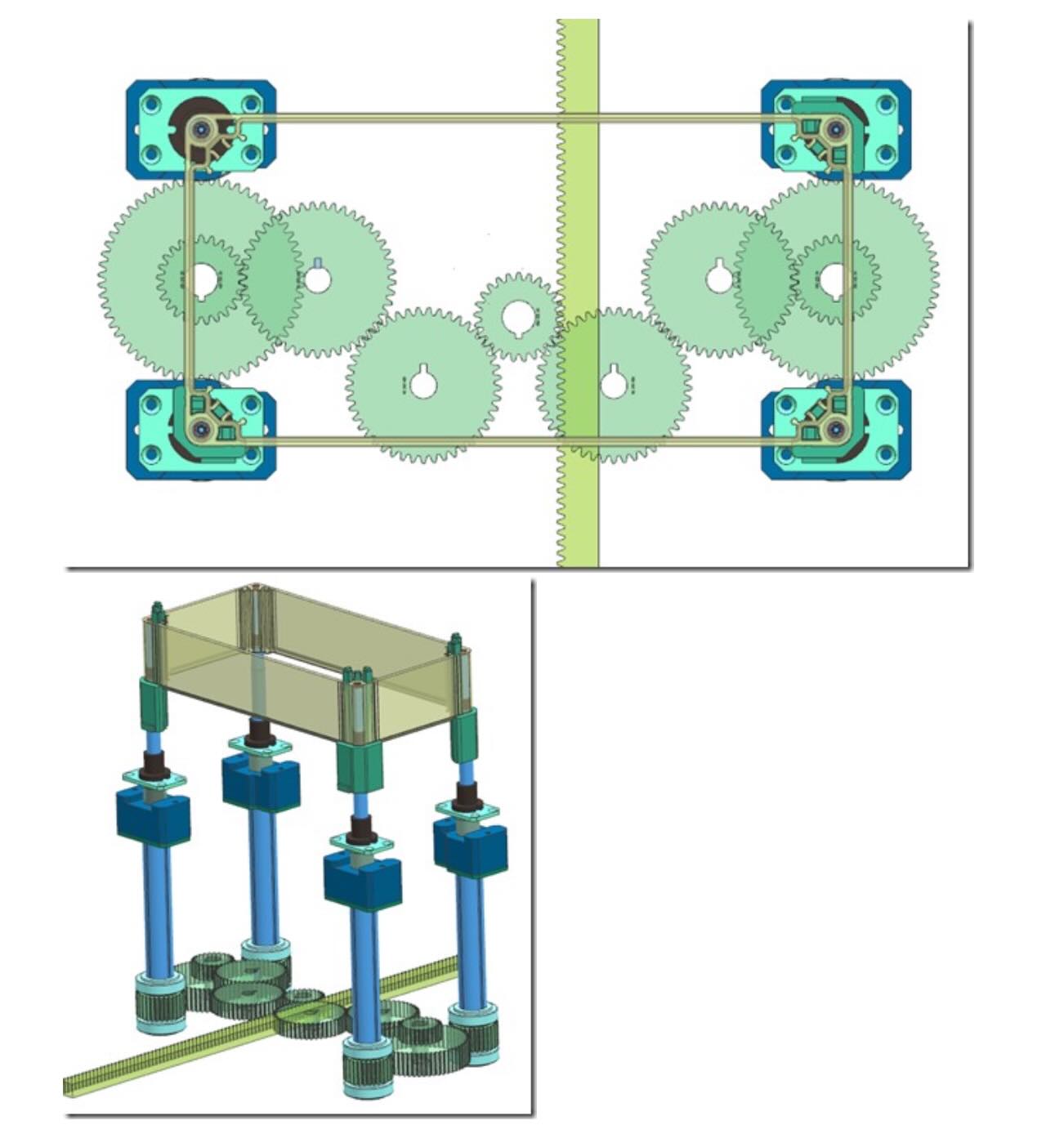
Recently, Vega Technical Dep. was asked to support the design of a complex unscrewing system for an injection mold. The customer needed assistance selecting the hydraulic cylinders responsible for driving a rack-and-pinion mechanism used to unscrew multiple threaded cores.
The request appeared simple:
“Which hydraulic cylinder should we use?”
However, before performing any force calculation, Vega Technical Dep. identified a much more important question:
“Have we fully understood how the mechanism actually works?”
This question completely changed the engineering approach.
Understanding the Kinematics Before Calculating the Force
One of the most common mistakes in mechanical design is attempting to calculate forces before understanding the complete movement sequence.
In unscrewing molds, forces are generated not only by the plastic component itself, but also by the entire transmission system, including:
- hydraulic cylinders;
- rack mechanisms;
- pinions;
- gear reductions;
- threaded cores;
- extraction mechanisms;
- synchronization systems.
For this reason, Vega Technical Dep. requested the complete 3D model of the mold.
Several fundamental questions had to be answered before any calculation could begin:
- How many hydraulic cylinders were involved?
- How many racks were moving simultaneously?
- Were the gear systems mechanically linked?
- Were the cores unscrewing and extracting at the same time?
- How many threaded cores were connected to each transmission system?
- Which mechanical elements contributed to the total resistance?
Only after reconstructing the complete kinematic chain could the actual force calculation begin.
Why Unscrewing Systems Are Different
In a conventional hydraulic application, the cylinder force is often determined by the weight of the moving parts.
In unscrewing molds, however, the cylinder must overcome several different contributions simultaneously:
- thread stripping force;
- extraction force;
- friction between plastic and steel;
- friction in bearings and guides;
- gear transmission losses;
- rack and pinion efficiency losses.
The total force therefore becomes:
Ftotal = Funscrewing + Fpulling + Ffriction + Ftransmission
where:
- Funscrewing = force required to rotate the threaded core;
- Fpulling = force required to extract the plastic component;
- Ffriction = mechanical friction losses;
- Ftransmission = losses generated by the transmission system.
This means that the cylinder is not simply moving a component.
It is supplying energy to an entire mechanical system.
Converting Cylinder Force into Torque
In this application, the hydraulic cylinder did not directly rotate the threaded cores.
Instead, it moved a rack, which then generated torque through a pinion gear.
The relationship between force and torque is:
T = F × r
where:
- T = transmitted torque;
- F = cylinder force;
- r = pitch radius of the pinion.
This conversion is critical.
A small change in gear diameter can significantly modify the torque available at the threaded core.
Therefore, selecting a cylinder without understanding the transmission geometry can easily lead to serious sizing errors.
The Effect of Transmission Efficiency
Mechanical transmissions never operate at 100% efficiency.
Every gear mesh, bearing, and guide introduces energy losses.
The available output torque can therefore be estimated as:
Tout = Tin × ηⁿ
where:
- Tin = input torque;
- Tout = output torque;
- η = efficiency of each transmission stage;
- n = number of transmission stages.
This means that the force generated by the hydraulic cylinder decreases progressively as it passes through the mechanical transmission chain.
Ignoring these losses can lead to substantial underestimation of the required cylinder force.
Calculating the Force Required for Each Core
The analysis performed by Vega Technical Dep. showed that the total resistance of each threaded core could be expressed as:
Fcore = Funscrewing + Fstripping
where:
- Funscrewing represents the force required to rotate the thread;
- Fstripping represents the force required to overcome the adhesion and shrinkage forces of the molded plastic component.
After analyzing the geometry of the mold and the transmission system, Vega Technical Dep. calculated a required force of approximately:
Fcore ≈ 465 kgf
for each core connected to the Z29 transmission group.
This value was significantly higher than the customer initially expected.
Determining the Total Cylinder Force
The hydraulic cylinder was not driving a single threaded core.
It was responsible for moving the complete mechanical assembly.
The required cylinder force therefore became:
Fcylinder = (ΣFcore + Ffriction) / ηsystem
where:
- ΣFcore = total force required by all threaded cores;
- Ffriction = friction generated by guides and transmissions;
- ηsystem = overall transmission efficiency.
Only after considering all these contributions could the hydraulic cylinder be correctly sized.
The Difference Between Calculation and Engineering
This project illustrates a common misconception in industrial design.
Many engineers believe that engineering consists primarily of performing calculations.
In reality, calculations are often the easiest part of the process.
The difficult part is understanding what should actually be calculated.
The customer initially asked:
“Which cylinder should we use?”
The question Vega Technical Dep. had to answer was:
“How does this machine actually move?”
Only after answering the second question was it possible to answer the first one.
Lessons Learned
1. Force calculations require a complete understanding of the movement
A force cannot be calculated correctly if the kinematic system is not fully understood.
2. Unscrewing molds involve multiple simultaneous loads
Thread forces, extraction forces, friction, and transmission losses all contribute to the final cylinder sizing.
3. Gear transmissions create both advantages and losses
Mechanical transmission efficiency must always be considered.
4. The complete 3D model is often the most important engineering tool
Geometry defines the forces acting on the system.
5. Engineering begins before calculations start
The most important question is often not “How much force?”, but “What exactly is moving?”
Conclusion
At first glance, this project appeared to be a simple cylinder sizing exercise.
In reality, it required a complete analysis of the kinematics, transmission system, gear ratios, friction losses, and extraction forces.
By reconstructing the complete movement sequence before performing any calculations, Vega Technical Dep. ensured that the hydraulic system would be sized according to the actual operating conditions rather than simplified assumptions.
Because in engineering, you cannot calculate a force until you understand the movement.