Introduction
Slider mechanisms remain one of the most widely used solutions for releasing side undercuts in injection molds. Despite the growing adoption of hydraulic and servo-driven systems, mechanical sliders continue to dominate many tooling applications because of their simplicity, reliability, and cost-effectiveness.
Whenever a molded component contains side holes, snap-fits, grooves, hooks, windows, or external undercuts that cannot be released along the mold opening direction, a side-action mechanism becomes necessary.
This article examines two common mechanical solutions:
- Mechanism 4 – Slider Guide Parting Mechanism
- Mechanism 5 – Pull Plate Core Pulling Mechanism
Understanding their operating principles, limitations, and design considerations allows mold designers to select the most appropriate solution for a specific application.
Why Side Actions Are Necessary
A conventional two-plate mold opens along a single axis.
If the molded geometry contains an undercut perpendicular to that axis, direct ejection becomes impossible because the molded feature mechanically locks the part inside the cavity.
A slider introduces controlled lateral movement before ejection begins.
The sequence becomes:
- Mold opens
- Slider retracts
- Undercut is released
- Part is ejected
Without this additional movement, the component would either remain trapped in the mold or be damaged during ejection.
Mechanism 4 – Slider Guide Parting Mechanism
Operating Principle
This mechanism uses a guide plate containing a specially machined track.
A cylindrical roller or guide pin mounted on the slider follows the track profile during mold opening.
As the mold opens, the guide forces the slider to move laterally while maintaining precise alignment.
The result is a highly repeatable side-core extraction process.
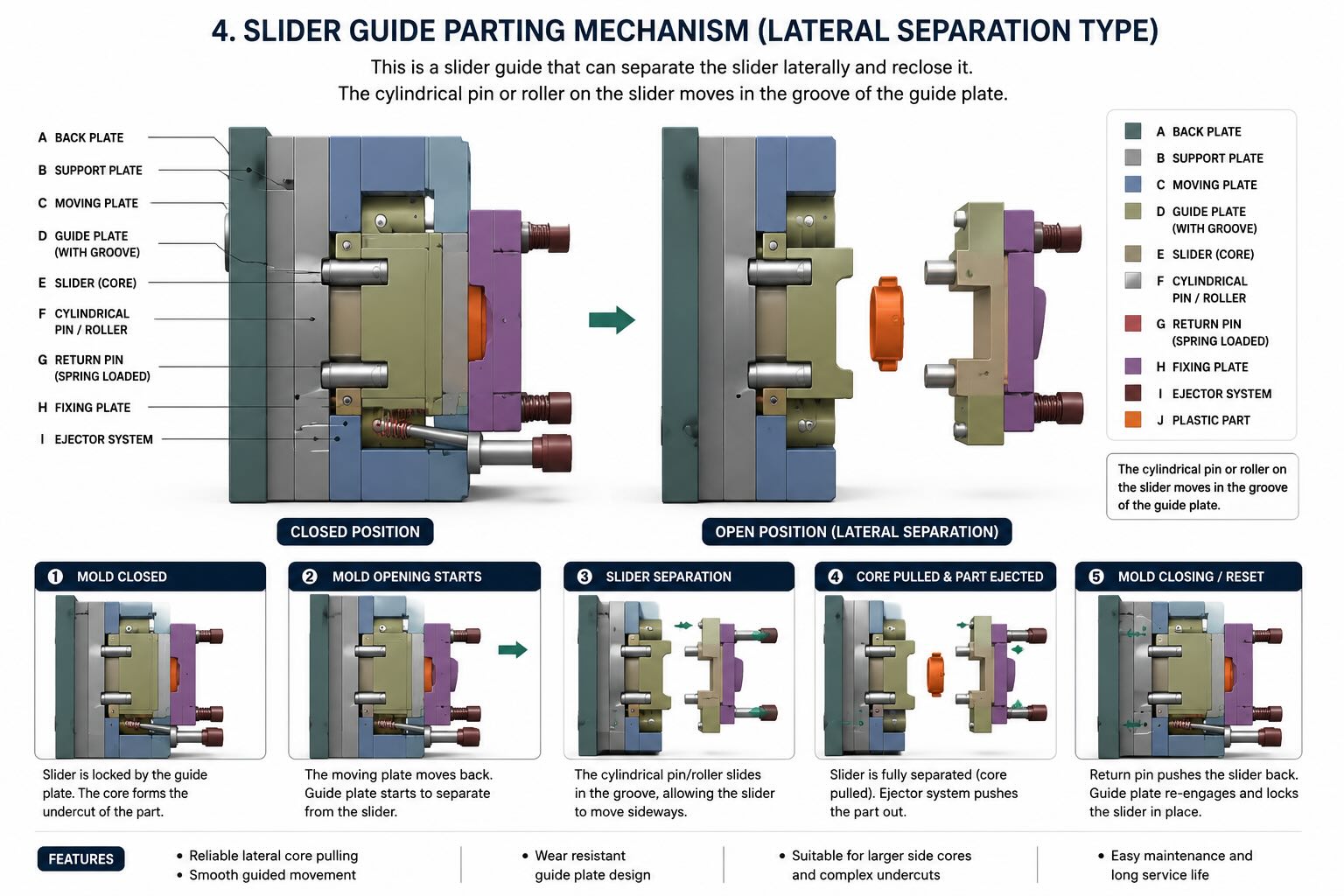
Motion Sequence
Phase 1 – Mold Closed
The slider is fully engaged.
The core forms the side undercut inside the molded component.
Phase 2 – Initial Mold Opening
The guide pin enters the angled section of the guide track.
The slider begins moving laterally.
Phase 3 – Core Retraction
The side core clears the undercut.
The molded part is now free from side interference.
Phase 4 – Part Ejection
The ejection system removes the part.
Engineering Advantages
- Excellent repeatability
- Accurate side-core positioning
- Compact installation
- No hydraulic system required
- Suitable for high-volume production
Design Limitations
Although simple, guide sliders have practical limitations:
| Parameter | Typical Range |
|---|---|
| Slider travel | 5–50 mm |
| Side load | Medium |
| Manufacturing cost | Low–Medium |
| Maintenance | Low |
| Cycle impact | Minimal |
For deep undercuts or long strokes, hydraulic systems may become more suitable.
Design Guidelines
When designing guide sliders, engineers should verify:
Bearing Surface Pressure
Insufficient bearing area increases wear.
As a rule, guide surfaces should distribute loads uniformly across the slider body.
Surface Hardness
Typical recommendations:
| Component | Hardness |
| Slider body | 50–58 HRC |
| Guide inserts | 58–62 HRC |
| Guide pins | 60–64 HRC |
Lubrication
Most slider failures originate from inadequate lubrication rather than insufficient strength.
Lubrication points should remain accessible during maintenance operations.
Common Failure Modes
Galling
Caused by excessive contact pressure and poor lubrication.
Flash Formation
Often generated by wear of guide surfaces.
Slider Seizure
Typically caused by contamination or insufficient clearance.
Premature Wear
Can result from excessive side loads generated by poorly designed angle pins.
Mechanism 5 – Pull Plate Core Pulling Mechanism
Operating Principle
In a pull plate mechanism, the slider is connected directly to a pull plate.
As the mold opens, the pull plate mechanically withdraws the slider from the undercut.
Unlike hydraulic systems, no external actuation is required.
The extraction stroke is synchronized with mold opening.
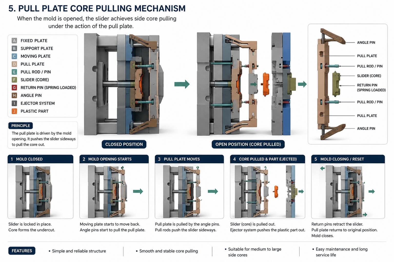
Motion Sequence
Phase 1 – Mold Closed
The side core forms the undercut.
Phase 2 – Mold Opening
The pull plate begins moving.
Phase 3 – Slider Retraction
The side core withdraws from the molded feature.
Phase 4 – Part Ejection
The molded component is ejected.
Engineering Advantages
- Simple construction
- Low manufacturing cost
- Minimal maintenance
- Reliable operation
- Excellent for medium-volume production
Design Limitations
The available stroke depends directly on mold opening distance.
Large side-core movements may require:
- longer mold opening strokes
- additional mechanical systems
- hydraulic assistance
Typical Engineering Applications
Pull plate systems are frequently used in:
- Packaging molds
- Electrical housings
- Consumer products
- Technical plastic parts
- Automotive interior components
Comparison Between Mechanism 4 and Mechanism 5
| Feature | Guide Slider | Pull Plate |
| Complexity | Medium | Low |
| Cost | Medium | Low |
| Maintenance | Low | Low |
| Positioning Accuracy | High | Medium |
| Stroke Capability | Medium | Medium |
| Reliability | High | High |
When Should a Slider Mechanism Be Used?
A mechanical slider remains the preferred solution when:
- The required stroke is below approximately 50 mm.
- No hydraulic circuit is available.
- Mold simplicity is a priority.
- Production volumes are high.
- Maintenance requirements must be minimized.
Hydraulic systems become more attractive when:
- Strokes exceed 50 mm.
- Large extraction forces are required.
- Motion timing must be independently controlled.
Common Design Mistakes
Experienced mold designers repeatedly encounter the following errors:
- Insufficient slider travel.
- Undersized guide surfaces.
- Inadequate lubrication access.
- Poor cooling layout around slider areas.
- Excessive contact pressure.
- Improper locking systems.
Most slider failures originate during the design stage rather than during production.
Conclusion
Slider mechanisms continue to represent one of the most efficient and economical methods for releasing side undercuts in injection molds.
Mechanism 4 provides superior positioning accuracy through guided movement, while Mechanism 5 offers exceptional simplicity and reliability through direct mechanical extraction.
When properly designed, both solutions can operate reliably for millions of molding cycles while maintaining dimensional accuracy and minimizing maintenance requirements.