Introduction
Undercuts in injection molded parts create one of the most common design challenges in mold engineering. If a molded feature prevents the part from being ejected directly from the cavity, an additional mechanism is required to release that geometry before ejection begins.
Ejector-driven core pulling mechanisms use the available motion of the ejection system to retract internal cores while simultaneously releasing the molded part.
While hydraulic systems and external side actions are often used in complex molds, many applications can be solved using simpler mechanical systems driven directly by the mold ejector movement.
These systems provide several advantages:
- Lower manufacturing cost
- Reduced mold complexity
- No external hydraulic circuit
- Reduced maintenance
- Compact design
- High reliability
However, ejector-driven systems also have limitations:
- Limited pulling force
- Limited stroke
- Increased sensitivity to wear
- Reduced suitability for large undercuts
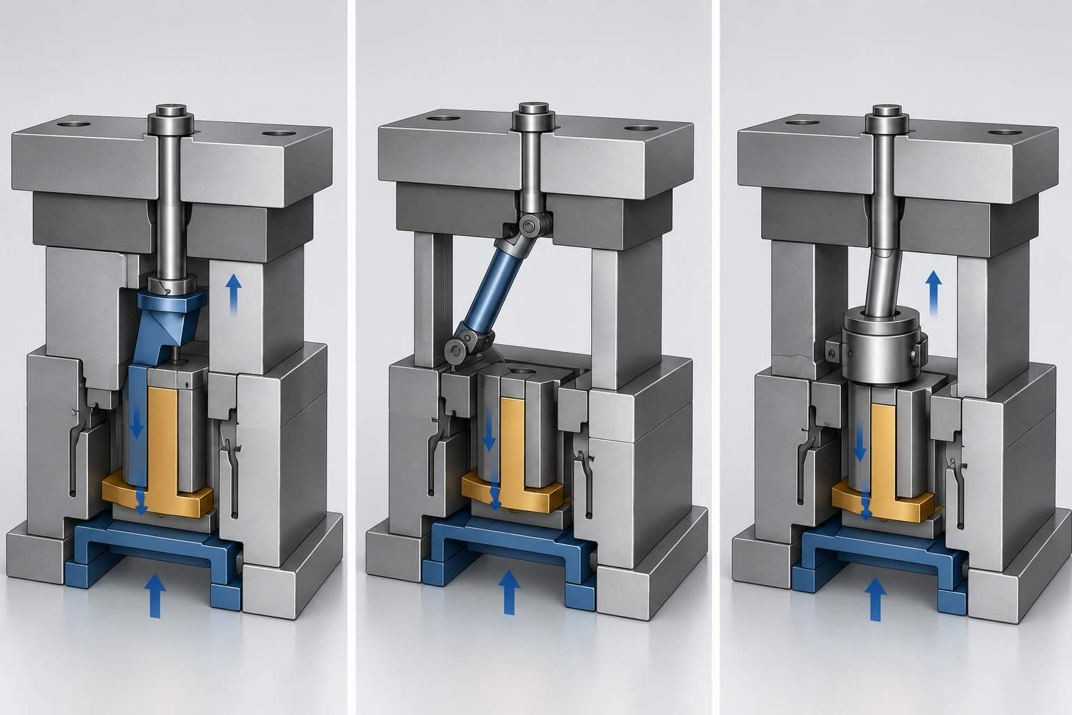
This guide analyzes three common ejector-driven mechanisms:
- Ejector Pin Translation Type Inner Core Pulling
- Hinged Inclined Push Rod Inner Core Pulling
- Cylindrical Cam Internal Core Pulling
Why Use Ejector-Driven Systems?
Traditional hydraulic side actions increase cost and mold size. In contrast, ejector-driven systems use existing mold motion without requiring additional power sources.
Typical applications include:
- Small undercuts
- Internal hooks
- Connector housings
- Plastic clips
- Consumer products
- Small automotive components
Typical engineering selection criteria:
| Parameter | Typical Range |
|---|---|
| Pulling force | 0.5–10 kN |
| Stroke | 3–25 mm |
| Complexity | Low |
| Maintenance | Low |
| Cost | Low |
Mechanism 1 — Ejector Pin Translation Type Inner Core Pulling
Working Principle
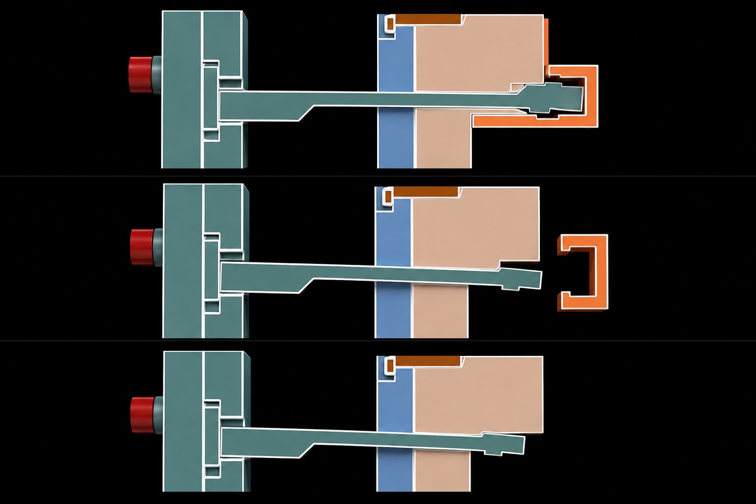
During ejection, the push rod initially moves linearly.
After reaching a predetermined distance:
- The inclined front face disengages the core
- The rear inclined surface contacts the moving mold plate
- The ejector pin begins moving toward the core
This movement creates simultaneous:
- part ejection
- core retraction
During mold closing:
- the front inclined surface resets the mechanism
Motion Sequence
- Mold opens
- Ejector system activates
- Front surface disengages core
- Rear surface redirects movement
- Core retracts
- Plastic part ejects
- Mechanism resets during mold closing
Advantages
- Compact construction
- No external power source
- Low manufacturing cost
- High reliability
Limitations
- Limited stroke capability
- Limited force generation
- Wear on inclined surfaces
Typical Applications
- Small internal undercuts
- Electrical connectors
- Plastic clips
- Consumer products
Common Failure Modes
| Problem | Cause | Solution |
|---|---|---|
| Pin wear | Excessive side load | Increase guide support |
| Core sticking | High friction | Improve surface finish |
| Incomplete release | Insufficient stroke | Increase travel distance |
Mechanism 2 — Hinged Inclined Push Rod Inner Core Pulling
Working Principle
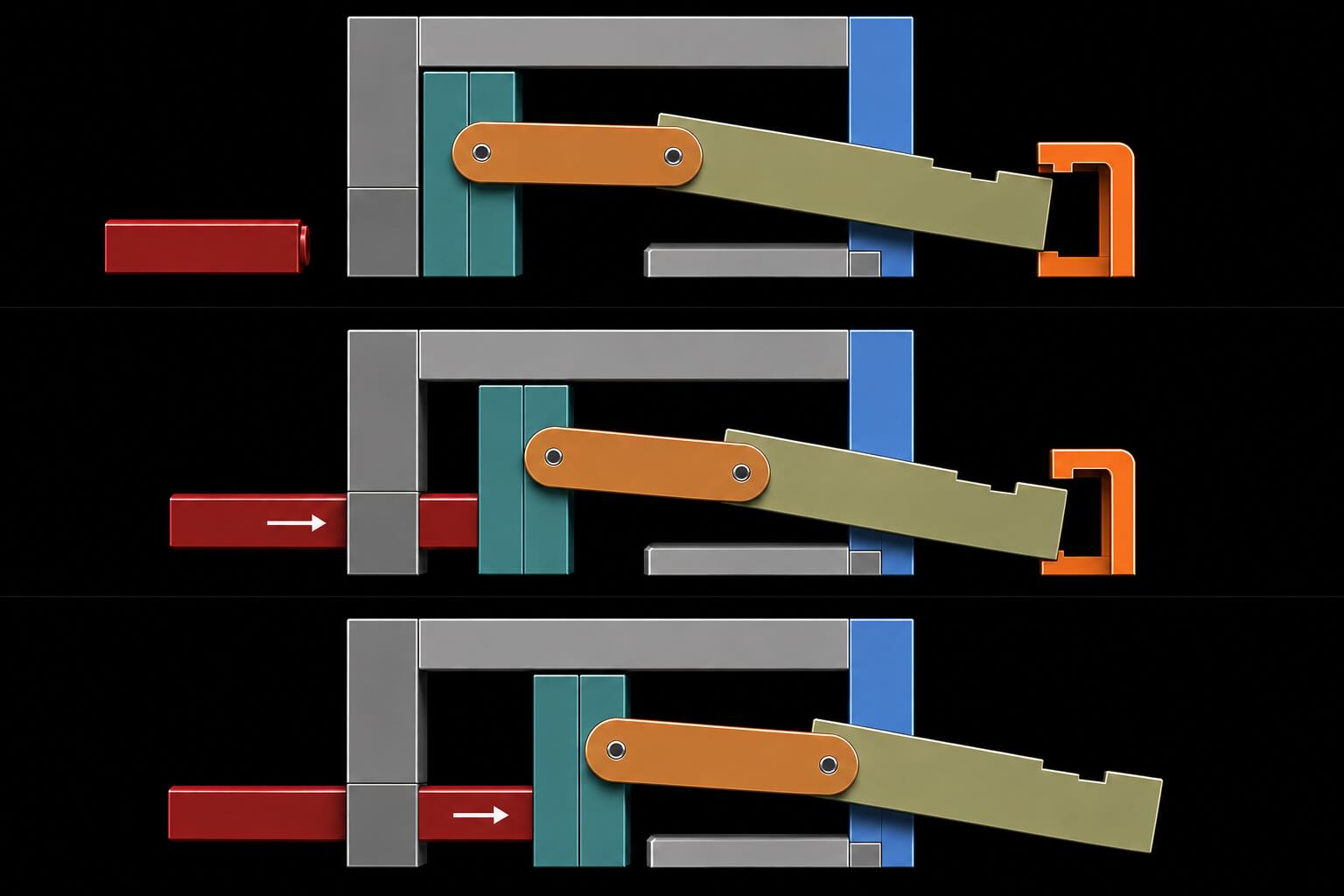
In this design, a connecting rod transfers motion between:
- push plate
- inclined push plate
During ejection:
- the push plate moves
- the connecting rod transmits force
- the inclined push rod moves through an angled guide
This simultaneously performs:
- internal core pulling
- plastic part ejection
Motion Sequence
- Mold opens
- Push plate activates
- Connecting rod transmits force
- Inclined rod moves
- Core retracts
- Part ejects
Advantages
- Improved force transmission
- Controlled movement
- Better motion synchronization
Limitations
- Increased mechanical complexity
- Additional wear points
- Alignment sensitivity
Typical Applications
- Medium undercuts
- Internal side features
- Small precision parts
Common Failure Modes
| Problem | Cause | Solution |
|---|---|---|
| Connecting rod wear | Excessive load | Increase rod diameter |
| Misalignment | Tolerance errors | Improve machining accuracy |
| Binding | Friction increase | Improve lubrication |
Mechanism 3 — Cylindrical Cam Internal Core Pulling
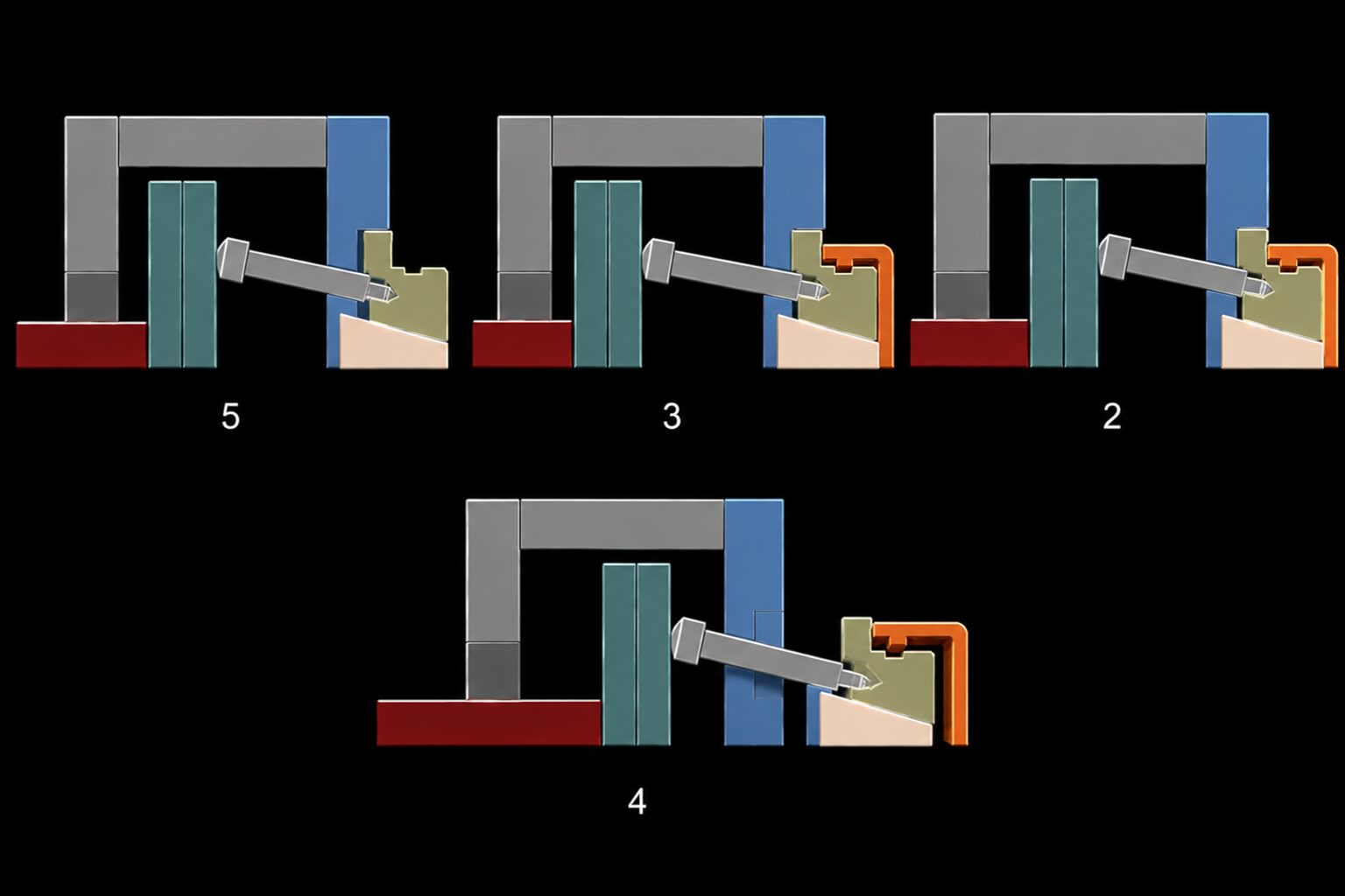
Working Principle
The cylindrical cam is guided through an inclined hole within the moving mold plate.
During ejection:
- the push plate moves
- the inclined rod pushes the cam
- the insert retracts
The movement simultaneously:
- retracts the internal core
- ejects the plastic component
Motion Sequence
- Mold opens
- Push plate advances
- Inclined rod drives cam
- Cam retracts insert
- Plastic component ejects
Advantages
- Better guidance
- Reduced lateral movement
- Improved positioning accuracy
Limitations
- More difficult machining
- Higher manufacturing cost
- Wear on cam surfaces
Typical Applications
- Precision molded components
- Internal side actions
- Small automotive parts
Technical Comparison
| Parameter | Mechanism 1 | Mechanism 2 | Mechanism 3 |
|---|---|---|---|
| Complexity | Low | Medium | Medium |
| Force capability | Low | Medium | Medium |
| Stroke | Low | Medium | Medium |
| Maintenance | Low | Medium | Medium |
| Cost | Low | Medium | Medium |
Engineer Selection Guide
Choose:
Mechanism 1 when:
- compact design is critical
- undercuts are small
- cost reduction is important
Choose:
Mechanism 2 when:
- additional force transmission is required
- movement synchronization matters
Choose:
Mechanism 3 when:
- better guidance accuracy is needed
- positioning precision is critical
Frequently Asked Questions
Which mechanism is best for small internal undercuts?
The Ejector Pin Translation mechanism is usually preferred due to its simplicity and low cost.
Can ejector-driven systems replace hydraulic systems?
Only for relatively small forces and short travel distances.
What is the main limitation of ejector-driven systems?
Limited pulling force and limited stroke.
Conclusion
Ejector-driven core pulling mechanisms remain among the most cost-effective solutions for small and medium undercut applications.
Selecting the proper system depends primarily on:
- available space
- required pulling force
- undercut geometry
- stroke requirements
- maintenance considerations
Proper selection during the mold design phase reduces manufacturing cost, improves reliability, and minimizes long-term maintenance issues.