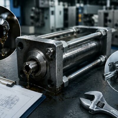
Controlled extraction motions
As molded part geometries become increasingly complex, traditional side actions are not always capable of providing the stroke, motion path, or extraction sequence required by the application.
In these situations, mold designers often rely on advanced core pulling systems that use racks, pinions, articulated linkages, and curved core mechanisms to transform mold opening movement into controlled extraction motions.
This article examines four advanced solutions:
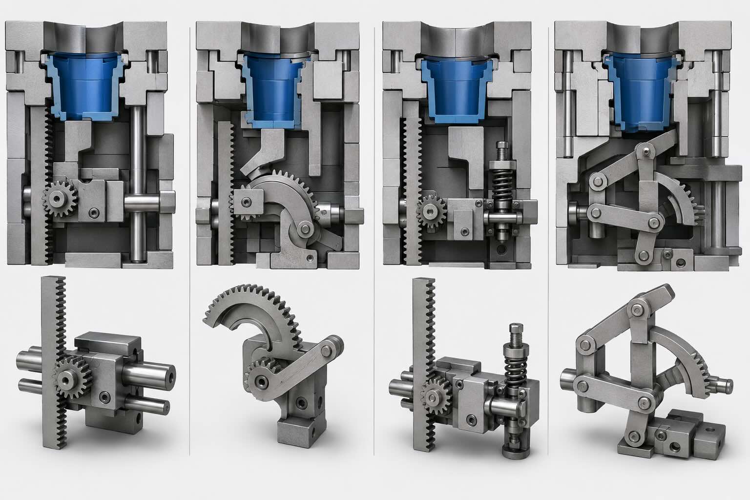
- Mechanism 6 – Rack-and-Pinion Oblique Core Pulling
- Mechanism 7 – Rack-and-Pinion Arc Core Pulling
- Mechanism 8 – Mold-Opening Driven Rack-and-Pinion Mechanism
- Mechanism 9 – Linkage-Driven Arc Core Pulling Mechanism
These systems often represent the ideal alternative to hydraulic cylinders when designers want to reduce maintenance, simplify mold construction, and improve long-term reliability.
When a Traditional Side Action Is Not Enough
Conventional side actions perform well for:
- linear movements;
- shallow undercuts;
- moderate extraction strokes;
- simple part geometries.
However, more sophisticated solutions become necessary when the application requires:
- curved extraction paths;
- long strokes;
- synchronized movements;
- arc-shaped cores;
- compact installation spaces.
In these situations, advanced kinematic systems can provide greater flexibility and motion control.
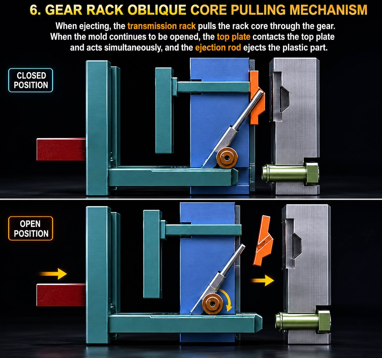
Mechanism 6 – Rack-and-Pinion Oblique Core Pulling
Operating Principle
During mold opening, a rack is driven linearly and rotates a pinion.
The rotational movement is then converted into controlled extraction motions of the side core.
Unlike traditional side actions, the gear ratio can be optimized to increase stroke length or modify extraction speed.
Engineering Advantages
- Long extraction strokes
- Excellent repeatability
- Precise motion control
- No hydraulic system required
Design Challenges
The gear train must be properly sized to avoid:
- tooth wear;
- backlash;
- loss of synchronization;
- excessive contact stress.
Typical Applications
- Automotive components
- Industrial connectors
- Technical housings
- Deep undercut applications
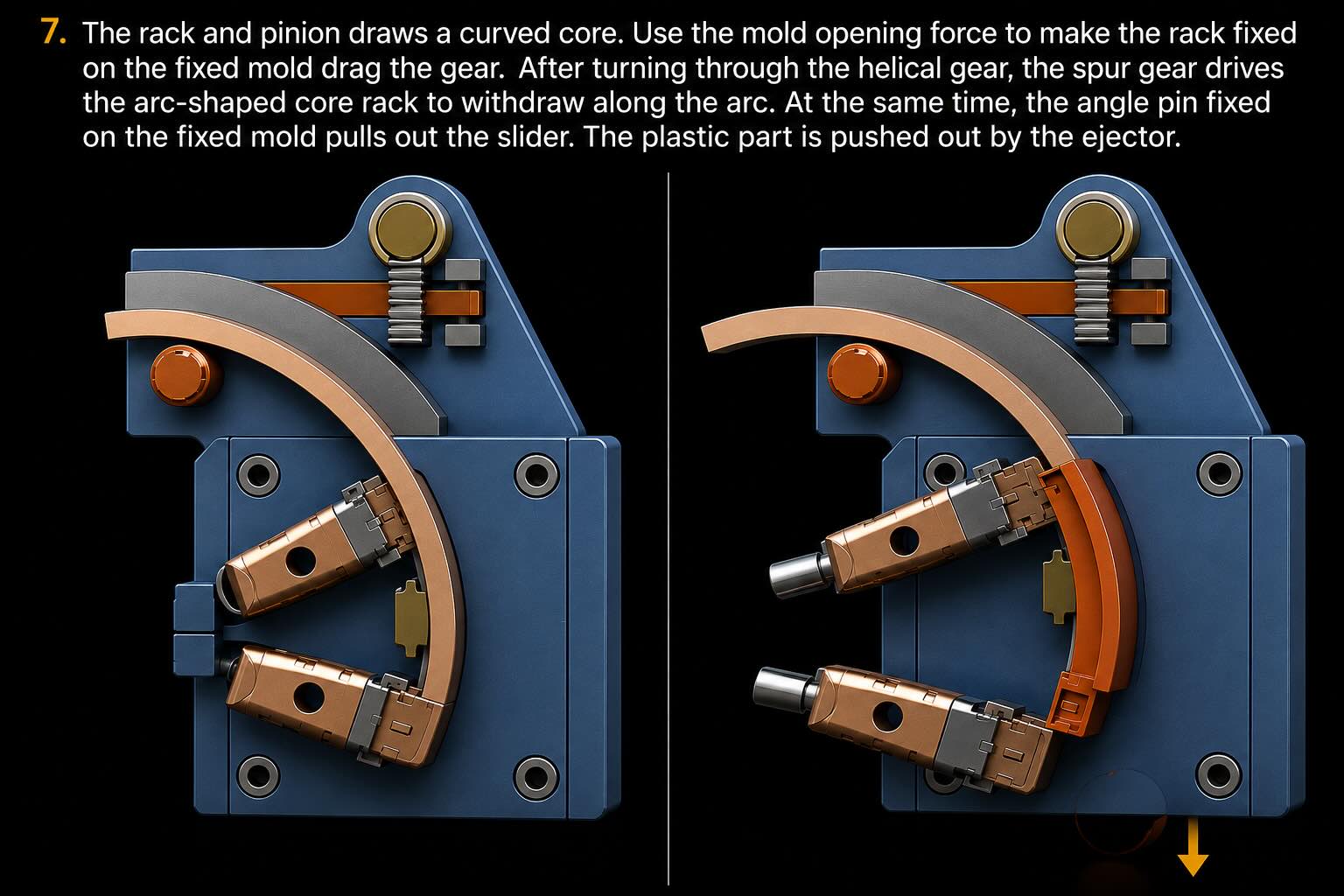
Mechanism 7 – Rack-and-Pinion Arc Core Pulling
Operating Principle
This mechanism converts linear rack motion into controlled rotation of an arc-shaped core.
Instead of moving along a straight path, the core follows a predefined curved trajectory.
This allows extraction of geometries that would be impossible to release using conventional side actions.
Design Considerations
The extraction path depends on:
- pinion diameter;
- rack geometry;
- arc-core radius;
- guide accuracy.
Even small alignment errors can significantly affect extraction performance.
Common Failure Modes
- Excessive gear backlash
- Tooth wear
- Misalignment
- Poor lubrication
Typical Applications
- Medical components
- Technical closures
- Curved undercuts
- Fluid connectors
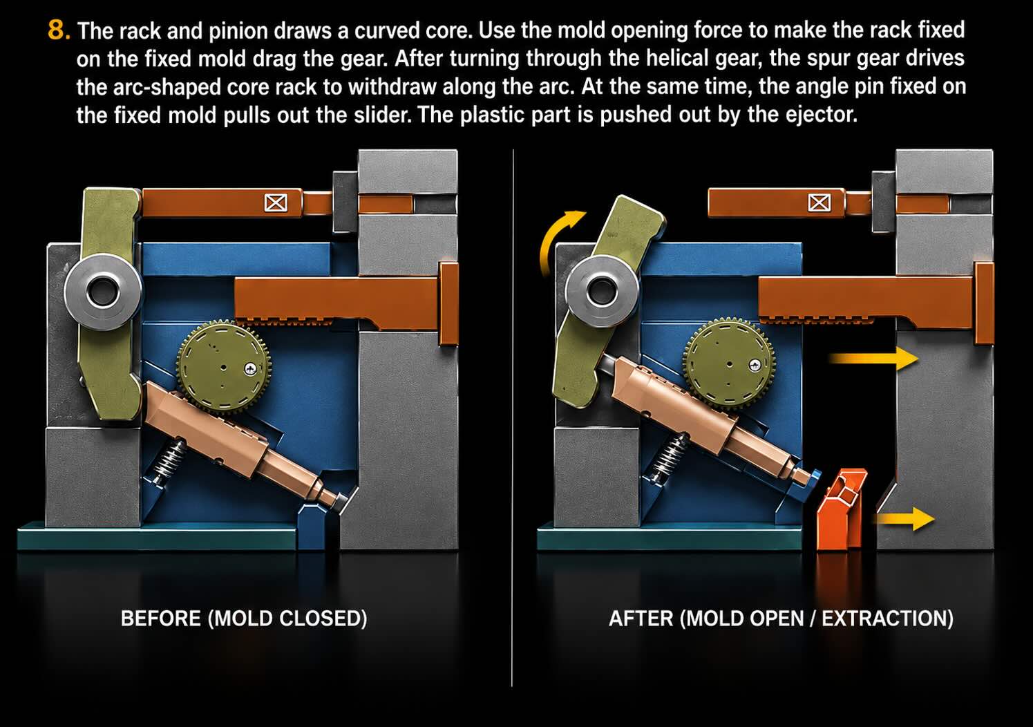
Mechanism 8 – Mold-Opening Driven Rack-and-Pinion System
Operating Principle
This mechanism uses the mold opening movement itself as the power source.
A rack is driven directly by mold separation and rotates a pinion, which then retracts the side core.
No external hydraulic or pneumatic actuation is required.
Engineering Advantages
- High reliability
- Reduced maintenance
- Lower manufacturing cost
- Fully mechanical operation
Critical Design Areas
Particular attention should be given to:
- positioning pins;
- spring-loaded locking systems;
- end-of-stroke impact loads.
If these elements are undersized, positioning accuracy may deteriorate over time.
Typical Applications
- High-volume molds
- Multi-cavity molds
- Consumer products
- Industrial plastic components
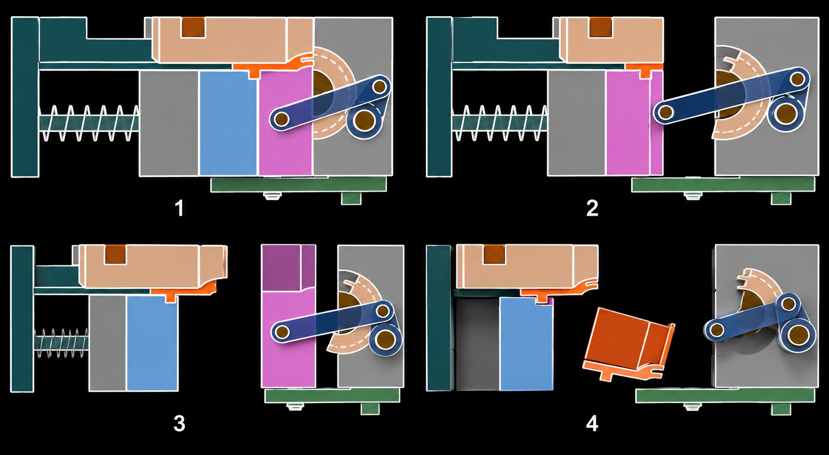
Mechanism 9 – Linkage-Driven Arc Core Pulling
Operating Principle
Mechanism 9 is one of the most sophisticated purely mechanical core pulling systems.
As observed in the motion sequence, the arc core is not driven directly by a gear train.
Instead, mold opening activates a sliding member that drives an articulated linkage.
The linkage rotates around a fixed pivot and progressively transfers motion to the arc-shaped core.
This creates a controlled extraction path capable of releasing complex undercuts while maintaining a compact mold design.
Kinematic Analysis
The behavior of the system depends on:
- linkage length;
- pivot location;
- arc-core radius;
- available stroke.
Small dimensional changes can significantly affect:
- extraction angle;
- transmitted force;
- extraction speed;
- synchronization.
Engineering Advantages
- Exceptional motion control
- Progressive extraction
- Reduced interference risk
- Suitable for complex geometries
Design Limitations
- Greater design complexity
- More moving components
- Higher manufacturing cost
- Increased maintenance requirements
Typical Applications
- Technical closures
- Threaded components
- Complex fluid fittings
- Curved undercut geometries
Technical Comparison
| Feature | M6 | M7 | M8 | M9 |
|---|---|---|---|---|
| Complexity | Medium | High | Medium | Very High |
| Precision | High | Very High | High | Very High |
| Stroke Capability | High | Medium | High | Medium |
| Cost | Medium | Medium-High | Medium | High |
| Maintenance | Medium | Medium | Low | Medium |
| Curved Motion | No | Yes | No | Yes |
Recommended Materials
| Component | Typical Material |
| Rack | Hardened Tool Steel |
| Pinion | Hardened Tool Steel |
| Pivot Pins | Bearing Steel |
| Bushings | Bronze or Coated Steel |
| Guides | Nitrided Steel |
Recommended hardness values:
- Racks: 58–62 HRC
- Pinions: 58–62 HRC
- Pivot Pins: 60–64 HRC
Preventive Maintenance
Every 250,000 Cycles
- Verify lubrication
- Check backlash
- Inspect guide surfaces
Every 1 Million Cycles
- Inspect gear wear
- Check pivot clearance
- Verify alignment
Every 2 Million Cycles
- Replace heavily loaded wear components
- Inspect arc-core guides
- Review synchronization accuracy
Common Design Mistakes
The most common engineering errors include:
- Insufficient extraction stroke
- Incorrect motion ratios
- Undersized gear teeth
- Flexible linkages
- Undersized pivots
- Poor lubrication access
- Core-to-part interference
Most of these issues originate during the design stage rather than during production.
How to Select the Right System
Choose Mechanism 6 when:
- Long linear extraction is required.
- High precision is needed.
- Mold space is limited.
Choose Mechanism 7 when:
- The core must follow a curved trajectory.
- The part contains complex undercuts.
Choose Mechanism 8 when:
- Simplicity and reliability are priorities.
- Hydraulic systems are undesirable.
Choose Mechanism 9 when:
- Advanced kinematic control is required.
- Complex curved extraction paths are necessary.
Conclusion
Advanced core pulling mechanisms allow mold designers to produce parts that would be difficult or impossible to manufacture using conventional side actions alone.
By combining racks, pinions, linkages, and arc-core systems, these mechanisms provide greater design flexibility, longer extraction strokes, and highly controlled motion paths.
When properly designed and maintained, they offer an excellent balance between performance, reliability, and operating cost, often eliminating the need for hydraulic systems while still handling highly complex molded geometries.