Hydraulic Cushioning in Injection Mold Cylinders: Engineering Principles, Design Criteria and Practical Limits
Introduction
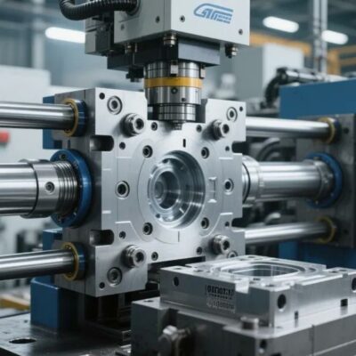
Hydraulic cylinders used in injection molds are generally selected according to force, stroke and installation dimensions. However, one design parameter is often underestimated during the engineering phase: end-of-stroke energy management.
When heavy ejection plates, core-pulling systems, sliders and moving mold assemblies operate at increasing speeds, the challenge is no longer simply generating sufficient force. The real challenge becomes stopping moving masses without generating destructive impact loads.
Hydraulic cushioning has been developed precisely for this purpose. Properly designed cushioning transforms kinetic energy into controlled hydraulic losses, reducing mechanical stress and increasing the service life of the complete mold system.
The subject becomes increasingly important in modern injection molding environments where reduced cycle times and increased productivity continuously push cylinders toward higher operating speeds.
Why Mold Designers Should Care About Cushioning
Injection molds often include moving assemblies with considerable inertia:
- Ejection plates
- Large core pull systems
- Unscrewing mechanisms
- Sliding inserts
- Multi-core systems
- Hydraulic mold actions
Historically, many systems operated at conservative speeds of approximately:
0.1 m/s
At these speeds, impact energy is relatively small and may sometimes be tolerated without major consequences.
However, modern productivity requirements frequently increase operating speeds toward:
0.5–0.8 m/s
Although this increase may appear modest, kinetic energy grows according to:
Ek = (1/2) × m × v²
Where:
- Ek = kinetic energy (J)
- m = moving mass (kg)
- v = speed (m/s)
The critical factor is the square of velocity.
Doubling speed increases impact energy by a factor of four.
Consequently, even small increases in cylinder speed can significantly increase:
- Impact forces
- Pressure spikes
- Stress on mold components
- Guide wear
- Cylinder fatigue
- Mechanical failures
For this reason, hydraulic cushioning should be considered a design necessity rather than an optional feature.
Hydraulic Cushioning Operating Principle
Hydraulic cushioning functions as an energy dissipation mechanism.
As the piston approaches the end of its stroke, a cushioning pin mounted on the rod enters a dedicated cushioning chamber.
This action creates a nearly sealed oil volume.
The trapped hydraulic oil can then escape only through restricted passages.
As flow area decreases:
- Oil velocity increases
- Pressure losses increase
- Resistance force increases
- Kinetic energy is converted into heat
Instead of a sudden mechanical impact, the system experiences controlled deceleration.
An optimized cushioning system aims to provide:
- Nearly constant deceleration force
- Smooth energy absorption
- Precise damping adjustment
- Rapid restart capability
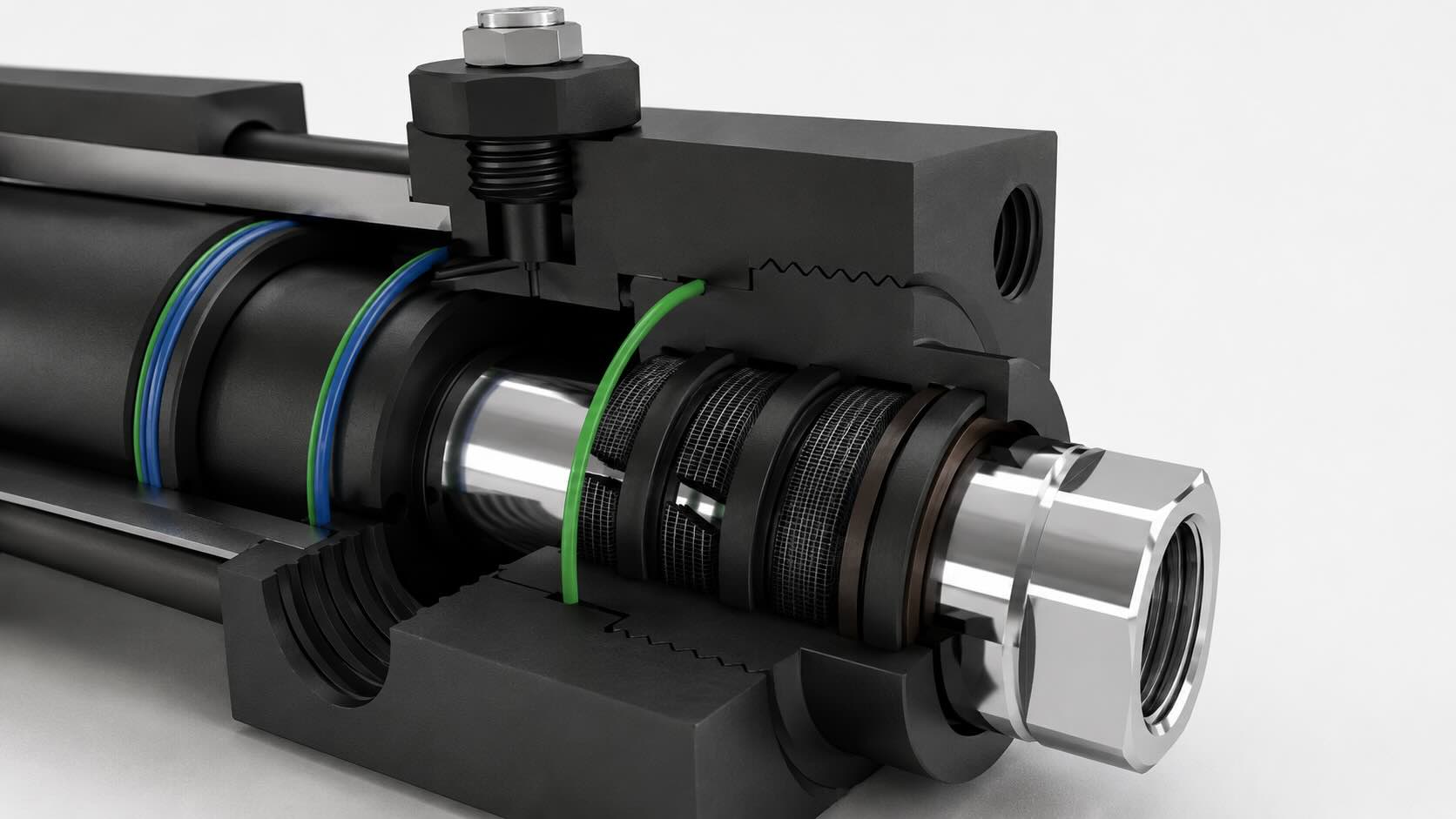
Components of a Hydraulic Cushioning System
A typical cushioning arrangement consists of several elements:
Cushioning pin
Installed on the piston rod and entering the cushioning chamber near the end of stroke.
Cushioning sleeve or bushing
Provides guidance and hydraulic sealing.
Oil passages
Restricted channels allowing controlled oil evacuation.
Adjustable needle mechanism
Permits fine tuning of damping characteristics.
Quick restart holes
Reduce hydraulic resistance during reverse motion.
Together these components create a controlled hydraulic braking effect.
Energy Dissipation Requirements
The key engineering question is:
“Can the cylinder safely absorb the moving energy?”
Several factors influence the required damping capability:
- Moving mass
- Speed
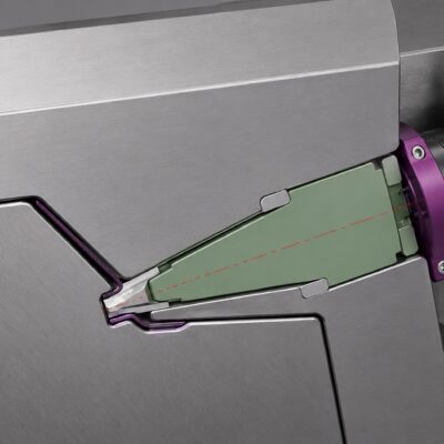
- Installation angle
- Friction
- Cushioning length
- Hydraulic pressure
The total deceleration force may be estimated using:
F = ma + (Ad × P /10) ± mg sinα − f
Where:
- F = total force acting on cushioning chamber (N)
- m = moving mass (kg)
- a = deceleration (m/s²)
- Ad = pressure area (mm²)
- P = hydraulic pressure (bar)
- g = gravity acceleration (9.81 m/s²)
- α = installation angle
- f = friction force
Deceleration itself can be estimated by:
a = v² / (2s)
Where:
- a = deceleration (m/s²)
- v = piston speed (m/s)
- s = cushioning length (m)
Vertical systems become especially critical because gravitational effects add additional energy that must be dissipated.
Practical Example: Ejection Plate Deceleration
Consider the following injection mold system:
Ejection plate dimensions
600 × 800 × 200 mm
Moving mass
750 kg
Cylinder quantity
2 cylinders
Cylinder bore
80 mm
Operating speed
0.5 m/s
The kinetic energy becomes:
Ek = (1/2) × 750 × (0.5)²
Result:
Ek = 93.75 J
Each cylinder therefore needs to dissipate:
47 J
If cushioning length equals:
26 mm
The required damping force becomes:
F = 47000 / 26
Result:
F ≈ 1800 N
Under working conditions around:
165 bar
A cylinder with:
- Bore 80 mm
- Rod diameter 36 mm
can safely absorb approximately:
112 J
A smaller cylinder:
- Bore 63 mm
- Rod diameter 28 mm
absorbs approximately:
67 J
Although still acceptable, the safety margin becomes smaller.
Vertical Applications: Why Problems Increase
Vertical systems create additional challenges because gravity contributes extra energy during deceleration.
Gravitational energy may be calculated as:
Eg = mgh
Where:
- Eg = gravitational energy
- m = mass
- g = gravity acceleration
- h = cushioning distance
For the same example:
Additional energy:
≈195 J
Additional load per cylinder:
≈100 J
Total energy per cylinder:
≈150 J
Under these conditions:
- Bore 80 mm remains acceptable
- Bore 63 mm approaches its operational limit
This explains why cylinders that appear adequate in horizontal systems sometimes fail in vertical applications.
Advantages of Hydraulic Cushioning
Reduced impact loading
Heavy moving masses stop progressively without mechanical shocks.
Higher operating speeds
Cylinder speeds may increase from approximately:
0.1 m/s
to:
0.7–0.8 m/s
under suitable conditions.
Reduced cycle time
Faster movements can improve production output.
Actual gains depend on:
- Cooling time
- Stroke length
- Machine limitations
Increased component life
Reduced impacts decrease:
- Seal wear
- Guide wear
- Fatigue stress
- Maintenance requirements
When Cushioning May Not Be Necessary
Hydraulic cushioning is not always beneficial.
Applications involving:
- Small moving masses
- Short strokes
- Low speeds
- Low inertia
may gain little advantage.
For example:
Bore = 80 mm
Cushion length = 26 mm
Stroke = 50 mm
More than half the stroke would occur under deceleration conditions, potentially reducing productivity rather than improving it.
Common Engineering Mistakes
Undersized cylinders
Using small cylinders with large moving masses may generate excessive pressure peaks and structural deformation.
Incorrect adjustment sequence
Improper cushioning adjustment can lead to:
- Leakage
- Unstable operation
- Poor damping performance
Cushioning with short strokes
The system may become unnecessarily expensive while providing little practical advantage.
Conclusion
Historically, hydraulic cushioning was considered an optional feature.
Modern mold engineering increasingly treats it as a critical design parameter.
As molds become:
- Larger
- Faster
- More automated
- More energy intensive
management of dynamic loads becomes equally important as static force calculations.
The most efficient mold systems are not those capable of moving masses faster.
They are the systems capable of stopping them intelligently.