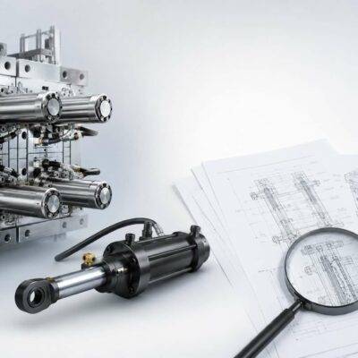
Hydraulic core pulling
As molded components become increasingly complex, conventional mechanical side actions are often unable to provide the stroke length, extraction force, or motion flexibility required by modern mold designs. Deep undercuts, large cores, complex geometries, and multi-stage extraction sequences frequently require a different approach.
This is where hydraulic core pulling systems become essential.
Unlike mechanically driven solutions that depend entirely on mold opening movement, hydraulic systems generate independent linear motion through hydraulic cylinders. This independence allows designers to control stroke length, extraction timing, speed, force, and sequencing with a level of flexibility that cannot be achieved using angled pins, rack-and-pinion systems, or other purely mechanical mechanisms.
Today, hydraulic core pulling systems are widely used in automotive molds, technical components, medical devices, industrial fittings, consumer products, and large structural plastic parts. Their ability to handle demanding molding conditions makes them one of the most versatile solutions available to mold designers.
Why Hydraulic Core Pulling Systems Are Used
Mechanical systems work exceptionally well when undercuts are relatively small and when mold opening movement can generate the required extraction travel.
However, certain applications introduce challenges that exceed the capabilities of traditional mechanisms.
Examples include:
- Deep undercuts requiring long extraction strokes.
- Large molded components generating high friction forces.
- Multiple cores requiring independent movements.
- Sequential extraction requirements.
- Tight installation spaces.
- Parts requiring controlled extraction timing.
In these situations, hydraulic cylinders can generate several tons of pulling force while maintaining accurate positional control.
The result is greater design freedom and significantly improved process reliability.
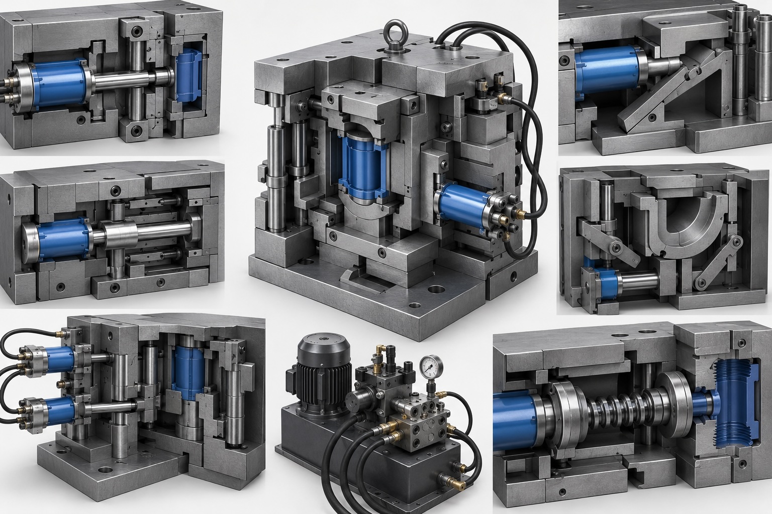
Mechanism 10 – Direct Hydraulic Side Core
Operating Principle
The simplest form of hydraulic core pulling uses a hydraulic cylinder directly connected to the core.
As the mold closes, the cylinder advances and positions the core into the molding cavity.
After cooling, the cylinder retracts and pulls the core away from the molded undercut before ejection occurs.
Because the cylinder directly drives the core, force transmission is highly efficient and mechanical losses are minimal.
Advantages
- Simple design
- High reliability
- Excellent force transmission
- Easy maintenance
- Suitable for large cores
Limitations
- Requires installation space
- Hydraulic plumbing required
- Higher initial cost
Typical Applications
- Pipe fittings
- Automotive connectors
- Technical housings
- Large undercuts
Design Notes
The cylinder should never be used as the sole guiding element. Dedicated guide systems must absorb side loads and maintain alignment throughout the stroke.
Mechanism 11 – Hydraulic Wedge System
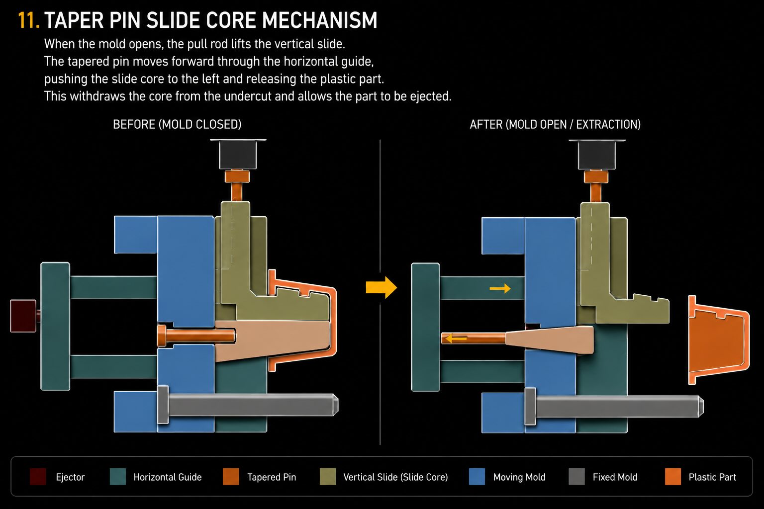
Operating Principle
In this configuration, a hydraulic cylinder drives a wedge mechanism that converts linear motion into another movement direction.
The wedge multiplies force and allows the designer to position the cylinder in locations where direct connection to the core would be impractical.
This arrangement is frequently used when available installation space is limited.
Advantages
- Compact installation
- Flexible packaging
- High extraction force
- Reduced mold dimensions
Limitations
- Increased friction
- Additional wear surfaces
- More complex manufacturing
Typical Applications
- Compact automotive molds
- Multi-cavity tools
- Technical components
Design Notes
Proper lubrication and surface hardening are critical because wedge interfaces experience substantial contact pressure.
Mechanism 12 – Guided Hydraulic Puller
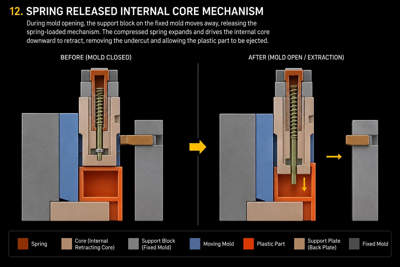
Operating Principle
A hydraulic cylinder drives a guided slide assembly supported by precision guide rails or wear plates.
The guide system absorbs side loads while the cylinder provides only the extraction force.
This design significantly improves system durability and positional accuracy.
Advantages
- Excellent repeatability
- Reduced cylinder wear
- Long service life
- High load capacity
Limitations
- Increased manufacturing cost
- Larger installation envelope
Typical Applications
- Precision molds
- Medical components
- Multi-cavity molds
- High-volume production
Design Notes
Guide surfaces should be designed to handle both static and dynamic loads generated during molding and extraction.
Mechanism 13 – Hydraulic Arc Core Pulling
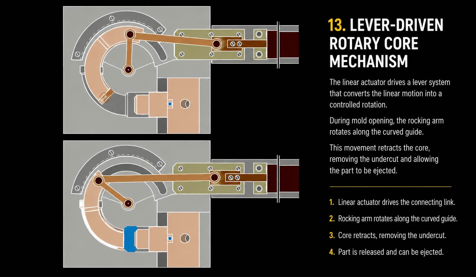
Operating Principle
Certain molded components contain curved undercuts that cannot be released using straight-line extraction.
In these cases, hydraulic motion is combined with a rotary linkage or curved guide track.
The core follows a controlled arc path during extraction.
This allows highly complex geometries to be molded without damaging the part during ejection.
Advantages
- Handles curved undercuts
- Enables complex geometries
- Excellent release characteristics
Limitations
- Complex machining
- Increased maintenance
- Higher tooling cost
Typical Applications
- Automotive air ducts
- Medical devices
- Consumer products
Mechanism 14 – Multi-Stage Hydraulic Core Pulling
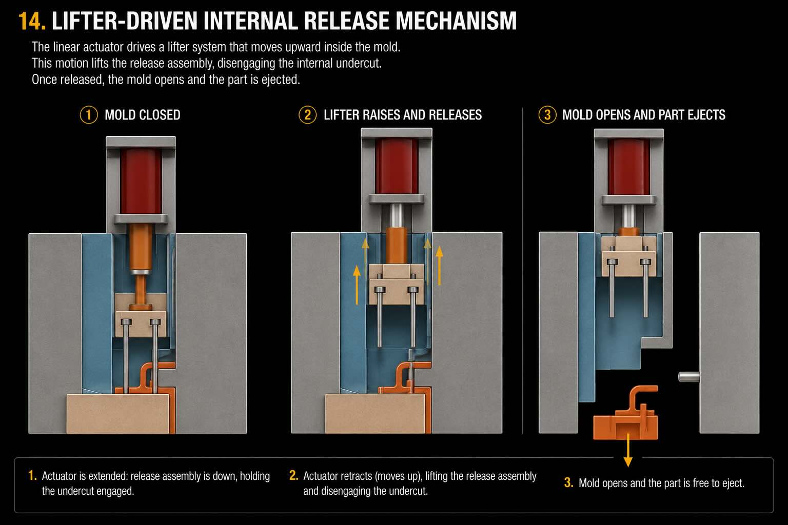
Operating Principle
Some molded parts require several extraction movements performed in a specific sequence.
A multi-stage hydraulic system coordinates multiple cylinders that operate independently.
Each core moves only when the previous motion has been completed.
Position sensors and PLC control ensure synchronization.
Advantages
- Extremely flexible
- Handles highly complex parts
- Programmable sequence control
Limitations
- Higher system complexity
- Increased setup time
- More sensors required
Typical Applications
- Large automotive components
- Technical assemblies
- Multi-undercut parts
Mechanism 15 – Hydraulic Unscrewing System
Operating Principle
Threaded molded features cannot be extracted using simple linear motion.
Hydraulic unscrewing systems convert hydraulic power into rotational movement.
The threaded core rotates while simultaneously retracting from the molded component.
This prevents thread damage and enables production of highly detailed threaded parts.
Advantages
- Produces accurate threads
- Eliminates thread damage
- Suitable for deep threaded features
Limitations
- Expensive
- Complex maintenance
- Longer cycle times
Typical Applications
- Caps and closures
- Industrial fittings
- Medical connectors
Hydraulic vs Mechanical Core Pulling
| Feature | Mechanical Systems | Hydraulic Systems |
|---|---|---|
| Force Capacity | Medium | Very High |
| Stroke Length | Limited | Very High |
| Motion Flexibility | Limited | Excellent |
| Control Precision | Moderate | High |
| Complexity | Low | Medium to High |
| Initial Cost | Lower | Higher |
| Maintenance | Low | Moderate |
Design Guidelines
Successful hydraulic core pulling systems begin with accurate force calculations.
Engineers must consider:
- Plastic shrinkage forces
- Core friction
- Guide friction
- Safety factors
- Mold operating pressure
Cylinder sizing should always include a safety margin to accommodate process variations and long-term wear.
Guidance systems should be designed independently from the hydraulic cylinder. Side loads should never be transmitted directly through the cylinder rod.
Position sensors should be incorporated whenever sequential operations are required.
Hydraulic circuits should also be designed to minimize pressure losses and ensure smooth motion during both extension and retraction.
Common Failures and Troubleshooting
The most common hydraulic core pulling failures include:
Oil Leakage
Usually caused by:
- Seal wear
- Incorrect installation
- Contamination
Core Misalignment
Common causes:
- Guide wear
- Improper assembly
- Structural deflection
Insufficient Pulling Force
Possible reasons:
- Pressure loss
- Incorrect cylinder sizing
- Internal leakage
Excessive Wear
Typically associated with:
- Poor lubrication
- High side loading
- Improper guide design
Regular inspection significantly reduces downtime and prevents unexpected failures.
Maintenance Recommendations
Preventive maintenance should include:
- Seal inspection
- Pressure verification
- Guide wear measurements
- Hydraulic hose inspection
- Sensor testing
- Fastener torque verification
A properly maintained hydraulic system can operate reliably for millions of molding cycles.
Conclusion
Modern molded components continue to increase in complexity, making hydraulic core pulling one of the most important technologies in advanced mold design.
Whether used for long-stroke extraction, high-force applications, curved cores, multi-stage sequences, or threaded features, hydraulic core pulling systems provide the flexibility and performance required by today’s most demanding injection molding applications.
For mold designers seeking maximum freedom and reliability, hydraulic core pulling remains one of the most powerful solutions available.