Introduction
Among all side-action technologies used in injection mold design, Angle Pin Mechanisms remain the most widely implemented solution for producing undercuts, side holes, external threads, snap features, and complex geometries that cannot be released directly along the mold opening direction.
Despite the increasing availability of hydraulic cylinders, servo-driven unscrewing systems, collapsible cores, and advanced lifter technologies, Angle Pin Mechanisms continue to dominate the injection molding industry because of their simplicity, reliability, relatively low manufacturing cost, and ability to operate without external power sources.
However, many mold designers understand only the kinematic movement of the angle pin and slider. True mastery requires understanding force transmission, wear behavior, thermal expansion, mold deflection, locking systems, ejection interaction, and maintenance considerations.
This article examines the engineering principles behind advanced angle pin systems and the nine most common configurations used in production injection molds.
Why Side Actions Are Required
The primary purpose of a side-action mechanism is to release features that create an undercut relative to the mold opening direction.
Typical examples include:
- Side holes
- Windows
- External threads
- Internal grooves
- Snap fits
- Cable tie anchors
- Automotive attachment clips
- Pneumatic connector ports
- Fluid passages
Without side-action mechanisms, the molded part would remain mechanically locked to the mold.
Before implementing any side-action system, experienced mold designers always ask a fundamental question:
Can the undercut be eliminated through product redesign?
This question often determines whether the mold will cost €15,000 or €150,000.
Design Philosophy: Eliminate Complexity First
The most successful mold designs are not necessarily the most sophisticated.
The best mold is often the simplest mold capable of producing the part reliably.
A common decision hierarchy is:
- Eliminate the undercut.
- Change the parting line.
- Use steel shut-offs.
- Use a lifter.
- Use a simple slider.
- Use an angle pin slider.
- Use hydraulic actuation.
- Use unscrewing mechanisms.
- Use collapsible cores.
Each step downward increases:
- Tooling cost
- Maintenance requirements
- Downtime risk
- Cycle time
- Manufacturing complexity
Therefore, Angle Pin Mechanisms should only be selected after simpler solutions have been evaluated.
Engineering Fundamentals of Angle Pin Mechanisms
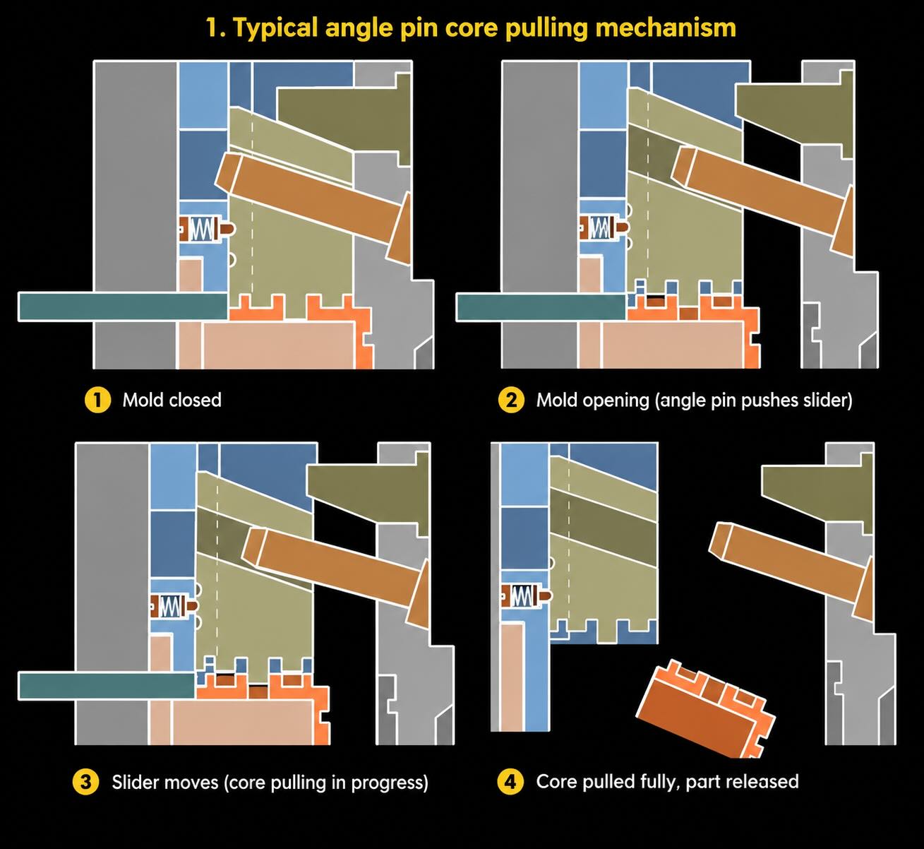
An angle pin converts mold opening movement into lateral slider movement.
The system functions as a mechanical cam.
The mold opening stroke creates a force component that acts perpendicular to the mold opening direction.
The force relationship is:
Fslider = Fopening × tan(θ)
where:
- Fslider = force acting on slider
- Fopening = mold opening force
- θ = angle pin angle
Small changes in angle significantly affect force transmission.
Angle Selection
The angle selected is one of the most important design decisions.
Small Angles (8°–12°)
Advantages:
- High pulling force
- Smooth operation
- Reduced impact loading
Disadvantages:
- Long mold opening stroke required
- Increased friction
Applications:
- Deep undercuts
- Large sliders
- Automotive molds
Medium Angles (15°–20°)
Advantages:
- Best compromise
- Most common industry standard
Applications:
- General-purpose molds
- Consumer products
- Medical devices
Large Angles (25°–30°)
Advantages:
- Short core-pull stroke
- Compact design
Disadvantages:
- Higher impact forces
- Increased wear
- Greater risk of pin breakage
Applications:
- Small side cores
- Limited mold space
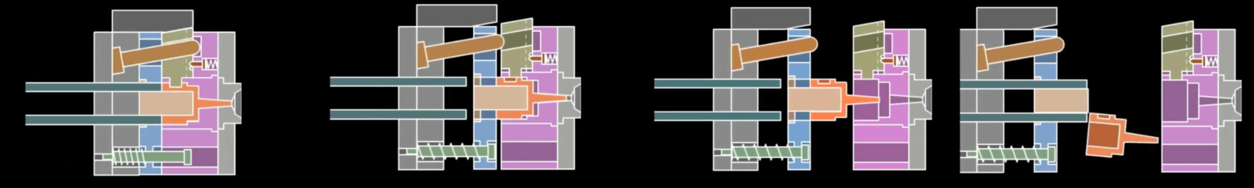
Mechanism 1: Standard Angle Pin Slider
The standard angle pin slider is the foundation of most side-action designs.
Components include:
- Angle pin
- Slider body
- Wear plate
- Gib
- Locking surface
- Retention screw
The slider retracts as the mold opens.
This design is suitable for:
- Side holes
- Shallow undercuts
- Connector housings
- Appliance components
Typical travel ranges:
- 5 mm to 50 mm
Typical slider weights:
- 0.5 kg to 40 kg
The major design concern is wear between the slider and guide surfaces.
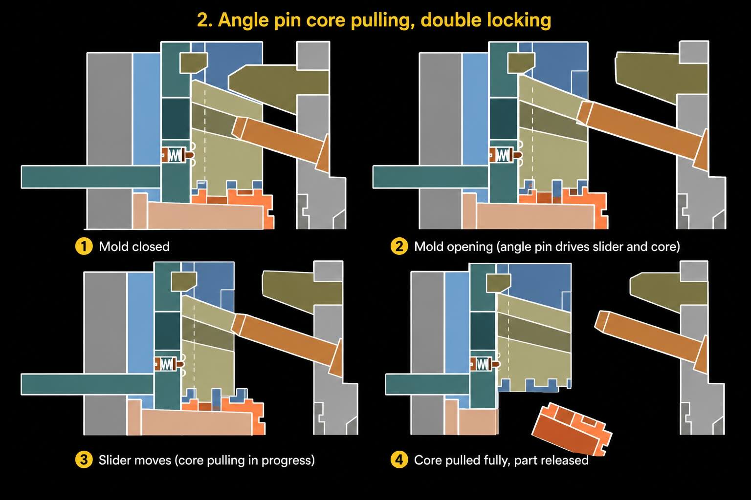
Mechanism 2: Double-Locking Angle Pin Systems
As cavity pressure increases, simple slider systems become vulnerable to flash formation.
The double-locking system introduces:
- Primary lock
- Secondary lock
The objective is to transfer injection forces into the mold structure rather than the angle pin.
A properly designed lock experiences:
- Compression loading
- Minimal shear stress
A poorly designed lock transfers force directly into the angle pin, eventually causing:
- Pin bending
- Slider mismatch
- Flash generation
- Core damage
Double-locking systems are commonly used in:
- Thin-wall packaging
- High-pressure engineering plastics
- Multi-cavity production molds
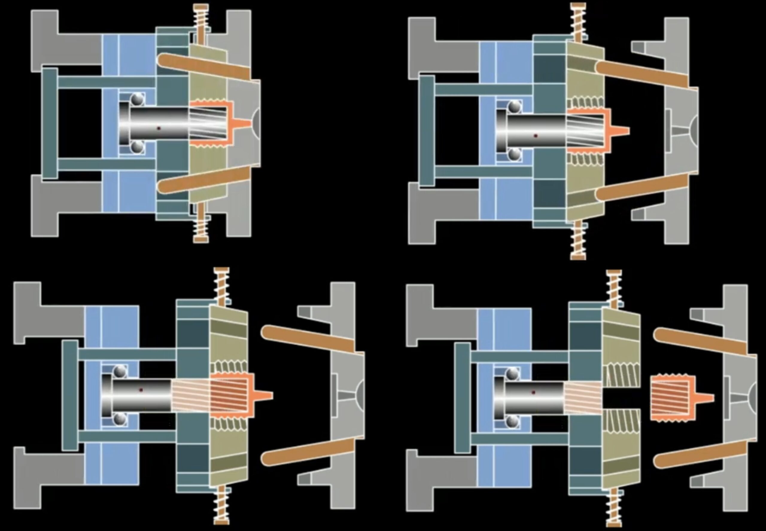
Mechanism 3: Thread Release Systems
Threaded features represent one of the most difficult challenges in mold design.
The angle pin itself does not remove the thread.
Instead, it creates a sequencing movement that assists:
- Unscrewing systems
- Rotating cores
- Stripper systems
Thread evaluation should consider:
- Pitch
- Lead angle
- Material flexibility
- Thread depth
- Production volume
Fine-pitch threads often require motor-driven unscrewing systems.
Coarse threads may be stripped directly.
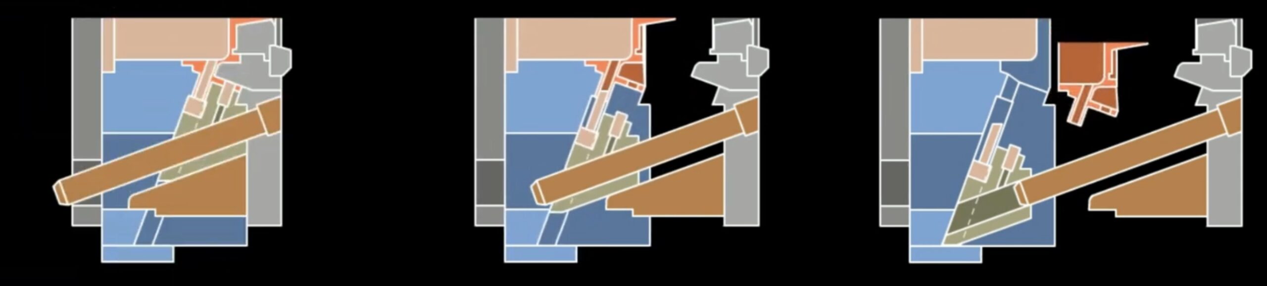
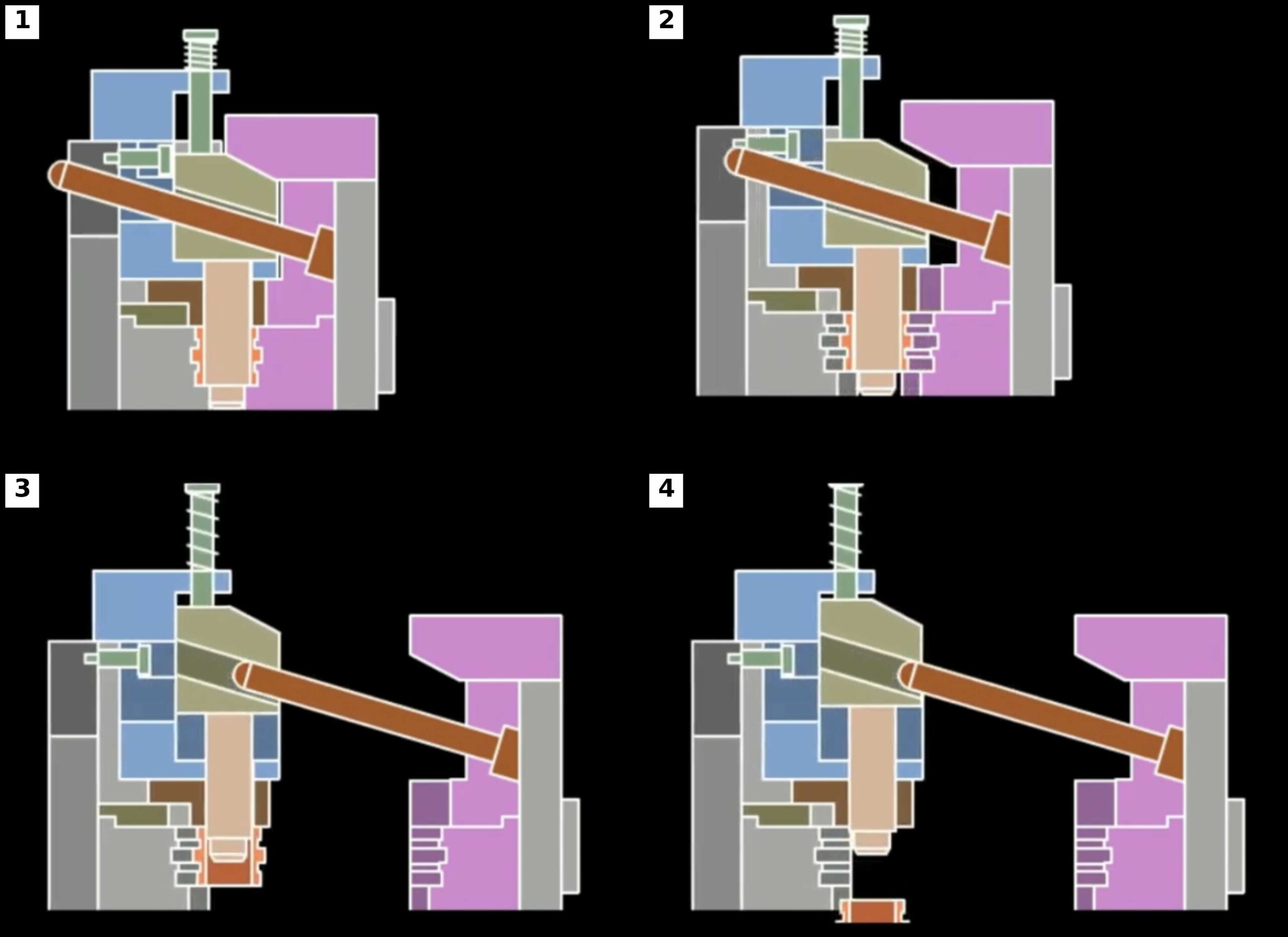
Mechanism 4: Oblique Core Pulling
Oblique core pulling is used when the undercut direction is not perpendicular to mold opening.
Applications include:
- Angled fluid passages
- Sensor ports
- Automotive mounting features
Critical considerations include:
Core Deflection
Long angled cores behave like cantilever beams.
Deflection increases with:
- Core length
- Injection pressure
- Melt viscosity
Designers often underestimate this effect.
Even 0.02 mm of movement can generate flash.
Mechanism 5: Angled Locking Parting Surfaces
An angled locking surface converts separation forces into compressive forces.
Benefits include:
- Reduced flash
- Better cavity alignment
- Longer mold life
Typical lock angles:
- 5°
- 10°
- 15°
Applications include:
- Large automotive components
- Thin-wall housings
- Precision engineering parts
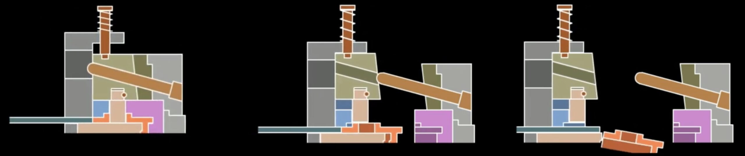
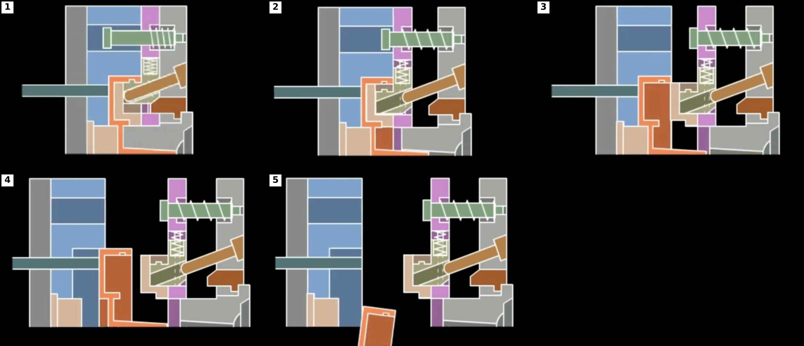
Mechanism 6: Fixed-Half Spring-Assisted Systems
These systems introduce sequencing.
The spring creates delayed movement.
Sequence:
- Mold begins opening.
- Slider moves.
- Undercut clears.
- Main parting line opens.
Advantages:
- Controlled movement
- Improved demolding
- Reduced part damage
Disadvantages:
- Spring fatigue
- Maintenance requirements
For high-volume production, nitrogen cylinders are often preferred.
Mechanism 7: Moving-Half Internal Core Pulling
Internal undercuts are significantly more challenging than external ones.
Problems include:
- Vacuum generation
- High friction
- Material shrinkage
As plastic cools, it contracts around the core.
The resulting retention force can exceed several thousand Newtons.
Design solutions include:
- Air assist
- Polished core surfaces
- Venting channels
- Reduced surface area
These systems are common in:
- Electrical connectors
- Medical fittings
- Pneumatic couplings
Mechanism 8: Fixed-Half Internal Core Pulling
Unlike moving-half systems, these designs require careful control of part retention.
The designer must ensure that the molded part transfers to the moving side.
Methods include:
Differential Draft
More draft on cavity surfaces.
Surface Texture Control
Higher polish on cavity side.
Strategic Gate Placement
Control shrinkage direction.
Failure to manage retention can result in:
- Part remaining in cavity
- Robot failures
- Cycle interruptions
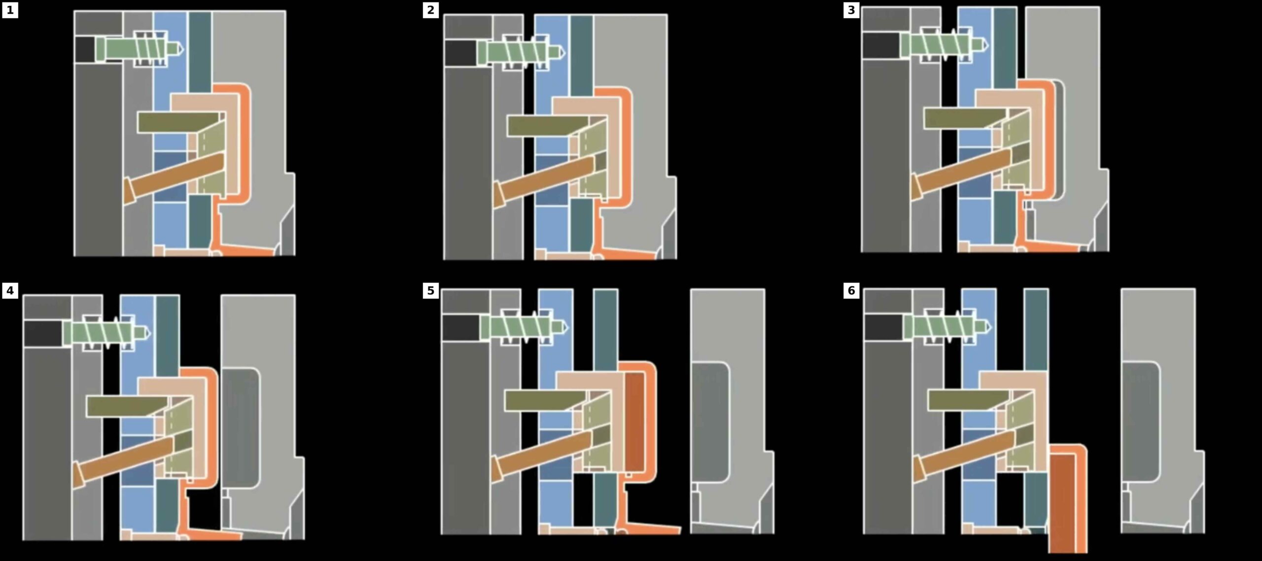
Mechanism 9: Floating Slider Systems
The floating slider is one of the most sophisticated forms of Angle Pin Mechanisms.
An idle travel zone is intentionally incorporated.
Sequence:
- Mold opens.
- Pin travels freely.
- Slider contact occurs.
- Slider movement begins.
- Core pulling starts.
Benefits include:
- Reduced shock loading
- Improved synchronization
- Better force management
These systems are common in:
- Automotive fascia molds
- Instrument panel molds
- Multi-slider tooling
Wear Analysis and Tribology
Most failures of Angle Pin Mechanisms are wear-related.
Major wear locations include:
- Pin contact surfaces
- Gibs
- Wear plates
- Lock blocks
Recommended hardness:
| Component | Hardness |
|---|---|
| Angle Pin | 58–62 HRC |
| Wear Plate | 58–62 HRC |
| Gibs | 56–60 HRC |
| Lock Blocks | 54–60 HRC |
Coatings often include:
- TiN
- DLC
- Nitriding
Proper lubrication remains essential.
Thermal Expansion Effects
A frequently overlooked issue is thermal growth.
A mold operating at 80°C can generate significant expansion.
Consequences include:
- Slider binding
- Alignment loss
- Increased friction
Large automotive molds often include:
- Expansion clearances
- Floating wear plates
- Thermal compensation features
Cooling Challenges
Cooling moving sliders is difficult.
Options include:
Bubbler Cooling
Simple but limited effectiveness.
Baffle Cooling
Improved thermal performance.
Conformal Cooling
The most advanced solution.
Additive manufacturing now allows conformal cooling channels inside slider assemblies.
Benefits include:
- Reduced cycle time
- Improved dimensional stability
- Better surface quality
Common Failure Modes
The most common failures include:
Pin Bending
Caused by:
- Excessive force
- Poor alignment
Slider Galling
Caused by:
- Lack of lubrication
- Poor surface finish
Flash Formation
Caused by:
- Worn locks
- Core deflection
Broken Springs
Caused by:
- Fatigue cycles
- Incorrect preload
Lock Damage
Caused by:
- Injection force overload
Future Trends
Modern injection molds increasingly combine traditional Angle Pin Mechanisms with:
- Additive-manufactured inserts
- Conformal cooling
- Mold sensors
- Position monitoring
- Industry 4.0 diagnostics
Smart molds can now detect:
- Slider position
- Wear progression
- Abnormal loads
- Lubrication failures
This transforms preventive maintenance into predictive maintenance.
Conclusion
Although hydraulic cylinders, electric drives, and collapsible cores continue to evolve, Angle Pin Mechanisms remain the backbone of side-action technology in injection molding.
Their success depends not merely on moving a slider but on understanding force transmission, locking geometry, thermal behavior, tribology, cooling, venting, and long-term wear.
The most effective mold designers recognize that a side-action mechanism is not an isolated component. It is part of a complete molding system in which product design, cavity construction, cooling, ejection, and manufacturing strategy must all work together.
When designed correctly, Angle Pin Mechanisms can operate reliably for millions of cycles while maintaining dimensional accuracy, minimizing maintenance, and delivering the productivity required in modern high-volume injection molding.