Introduction
Modern injection molded components are becoming increasingly complex. Automotive housings, industrial connectors, medical devices, consumer electronics, appliance components, and technical engineering parts frequently incorporate side holes, snap features, recessed geometries, locking structures, threads, and internal undercuts that cannot be released using a conventional two-plate mold.
Whenever an undercut prevents the molded component from being ejected directly from the cavity or core, a secondary movement must be introduced into the mold design. This secondary movement is commonly known as core pulling, side action, slider movement, or side core extraction.
For decades, angle pins have been the standard solution for actuating side cores. The principle is simple: as the mold opens, an inclined pin converts part of the mold opening stroke into lateral movement, allowing a slider to withdraw from the molded undercut.
Although angle pin systems remain widely used, they present several limitations. The contact area between the angle pin and the slider is relatively small. Large side cores generate significant loads on the pin surface, increasing contact pressure and wear. Long core-pulling distances require large mold opening strokes. Additional locking wedges are often required to maintain slider stability during injection.
As molded products have become larger and more sophisticated, mold designers have increasingly adopted square dowel core pulling systems.
A square dowel can be viewed as an advanced evolution of the conventional angle pin. Instead of a cylindrical profile, the driving component utilizes a rectangular cross-section. This geometry significantly increases the contact surface between the driving member and the slider, improving force transmission and reducing surface pressure.
The larger contact area enables square dowels to withstand greater loads while maintaining dimensional stability throughout the mold’s service life. In many cases, the square dowel itself performs both the pulling and locking functions, eliminating the need for separate wedge mechanisms.
Another significant advantage is the ability to utilize larger operating angles. Larger angles produce longer slider travel for a given mold opening distance, allowing compact mold designs while still accommodating deep undercuts.
Advanced square dowel systems may incorporate multiple slope sections, delayed engagement mechanisms, sequential motion control, roller-assisted movement, and variable-angle geometries. These designs provide engineers with substantial flexibility when solving difficult demolding challenges.
Today, square dowel mechanisms are commonly found in:
- Automotive exterior components
- Automotive interior trim
- Electrical connectors
- Appliance housings
- Medical devices
- Packaging systems
- Industrial valve components
- Pneumatic fittings
- Technical engineering products
Because side-action mechanisms directly influence mold reliability, cycle time, maintenance costs, and product quality, proper design of square dowel systems requires careful consideration of mechanical engineering principles, force transmission, wear characteristics, lubrication, manufacturing tolerances, and mold operating conditions.
This article examines the engineering fundamentals of square dowel mechanisms and analyzes twelve common configurations used throughout the injection molding industry.
Engineering Fundamentals of Square Dowel Systems
Motion Conversion Principle
The primary purpose of a square dowel mechanism is to convert mold opening movement into lateral slider movement.
As the injection molding machine opens the mold, linear movement occurs along the machine axis. The inclined surface of the square dowel transforms part of this movement into transverse motion.
The relationship between mold opening stroke and slider travel depends primarily on the inclination angle of the dowel.
Small operating angles generate large pulling forces but relatively short travel distances.
Large operating angles generate longer travel distances but lower mechanical advantage.
Selecting the proper angle therefore represents one of the most important design decisions in any square dowel mechanism.
Mechanical Advantage
The square dowel functions as an inclined plane.
Mechanical advantage can be understood by considering the relationship between the opening force generated by the molding machine and the resulting lateral force applied to the slider.
When a shallow angle is used, a larger portion of the mold opening force is converted into lateral pulling force.
This is particularly beneficial when:
- Deep undercuts exist
- Large sliders are required
- High friction must be overcome
- Molded parts exhibit significant shrinkage around the side core
However, shallow angles require longer mold opening strokes to achieve the same core-pulling distance.
Conversely, steeper angles increase travel but reduce available force.
This trade-off is the reason variable-angle square dowels have become increasingly popular in advanced mold designs.
Contact Surface Area
One of the primary advantages of square dowels over traditional angle pins is the significantly larger contact area.
In an angle pin system, force is concentrated along a relatively narrow contact zone.
The resulting contact pressure may become substantial when:
- Large sliders are used
- Injection pressures are high
- Molding materials generate significant shrinkage forces
Excessive contact pressure leads to:
- Surface wear
- Galling
- Deformation
- Reduced accuracy
- Premature maintenance
The rectangular geometry of the square dowel distributes the same force across a much larger area.
This lowers contact stress and improves long-term durability.
For high-volume production molds operating millions of cycles, this advantage becomes particularly important.
Friction Considerations
Every core-pulling mechanism must overcome friction.
Sources of friction include:
- Slider guide surfaces
- Gib surfaces
- Wear plates
- Locking surfaces
- Plastic shrinkage around the core
The total extraction force required may be significantly higher than expected.
Designers must account for:
- Dry friction
- Lubricated friction
- Surface finish
- Material hardness
- Operating temperature
Failure to properly estimate friction often results in:
- Sticking sliders
- Broken components
- Excessive wear
- Incomplete core withdrawal
Wear Mechanisms
Wear is one of the most common causes of side-action maintenance.
Several wear mechanisms may occur simultaneously.
Adhesive Wear
Adhesive wear occurs when microscopic surface asperities weld together under pressure and subsequently tear apart during movement.
Abrasive Wear
Hard particles become trapped between moving surfaces and act as cutting tools.
Galling
Galling is particularly dangerous in poorly lubricated steel-on-steel systems.
Material transfers from one component to another, rapidly damaging sliding surfaces.
Fatigue Wear
Repeated cyclic loading eventually creates microscopic cracks and material degradation.
Because square dowels distribute loads over larger surfaces, they typically exhibit longer service life than equivalent angle pin systems.
Locking Function
A critical requirement of every side-action system is maintaining precise positioning during injection.
Injection pressures may exceed 1000 bar inside the cavity.
These pressures generate substantial forces on side cores.
If the slider moves even slightly, flash, dimensional variation, and component damage may occur.
Traditional angle pin systems frequently require dedicated wedge locks.
Many square dowel systems inherently provide sufficient locking capability due to their geometry.
This simplifies mold construction and reduces component count.
Mold Opening Stroke Requirements
Every side-action mechanism must fit within the available machine opening stroke.
The required opening stroke depends on:
- Core-pulling distance
- Dowel angle
- Safety clearance
- Product geometry
- Ejection requirements
Large undercuts frequently dictate machine selection.
A properly designed square dowel system can significantly reduce required opening stroke compared to conventional solutions.
Advantages and Limitations of Square Dowel Mechanisms
Advantages
Increased Contact Area
The rectangular profile dramatically increases bearing surface.
Higher Load Capacity
Large side cores can be moved safely.
Improved Durability
Reduced contact stress improves service life.
Longer Available Travel
Steeper operating angles become practical.
Reduced Component Count
Separate wedges are often unnecessary.
Improved Mold Rigidity
Compact designs permit stronger mold structures.
Enhanced Reliability
Fewer components generally translate into fewer failures.
Limitations
Manufacturing Complexity
Precision machining requirements are greater than for angle pins.
Tight Tolerances
Misalignment can cause severe wear.
Lubrication Requirements
Large contact surfaces require proper lubrication management.
Maintenance Access
Embedded designs may be difficult to service.
Initial Cost
Manufacturing costs are generally higher than traditional angle pin systems.
Nevertheless, for demanding applications these disadvantages are often outweighed by the performance benefits.
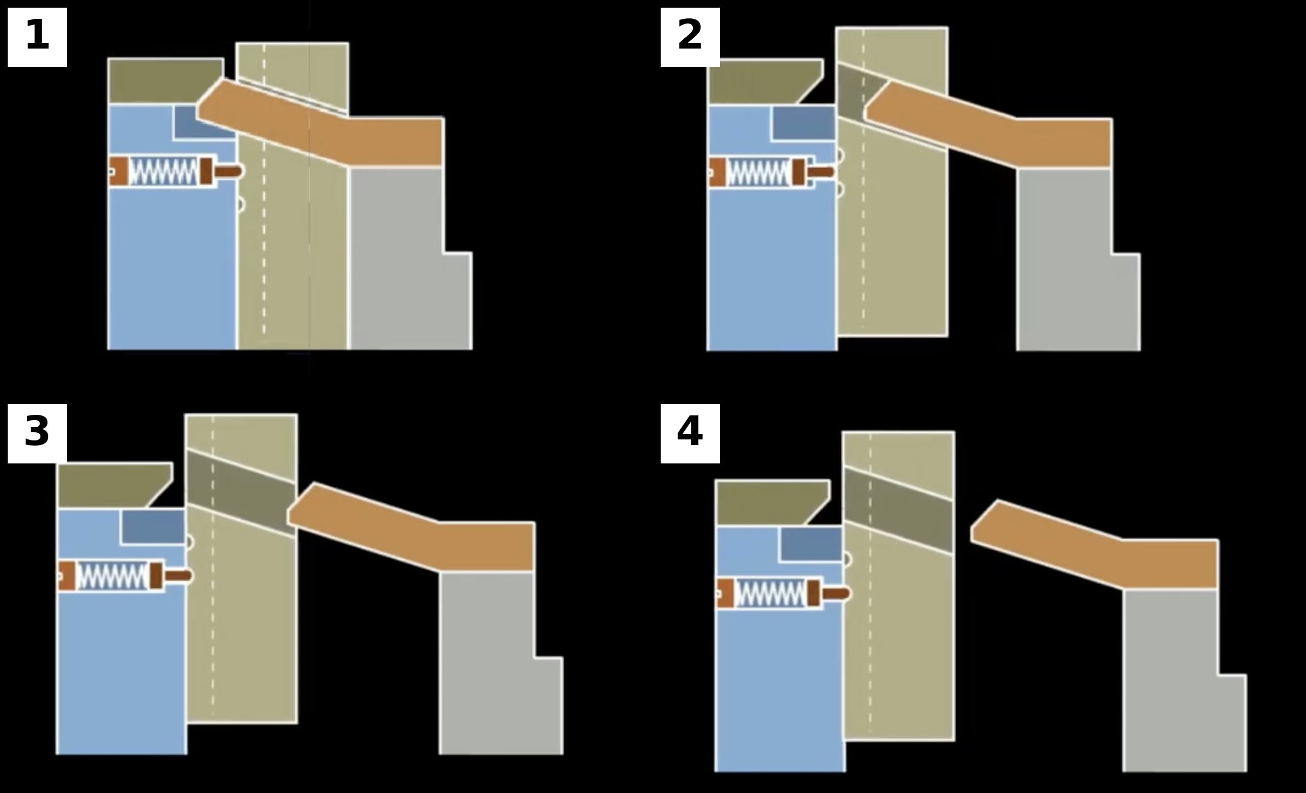
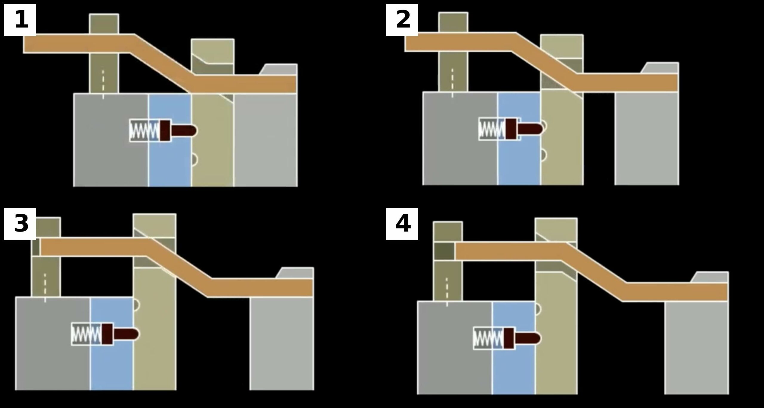
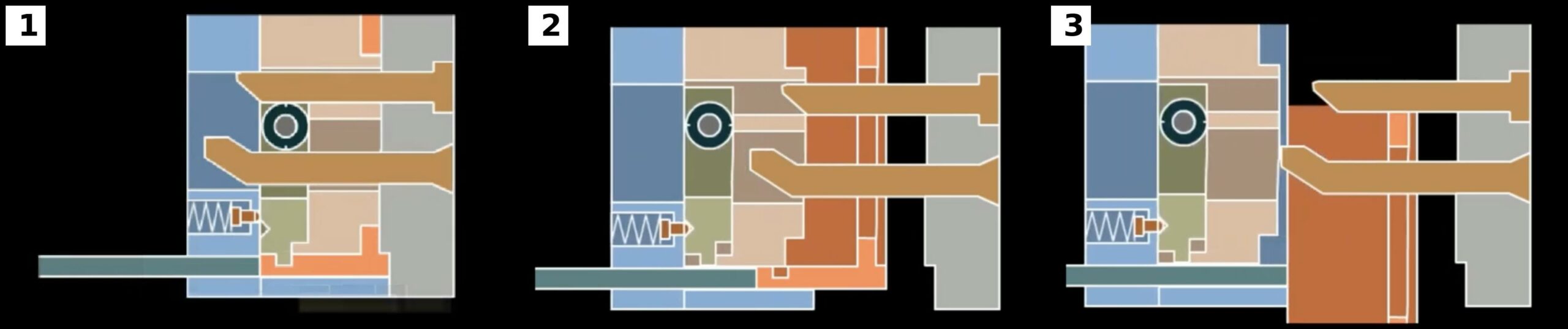
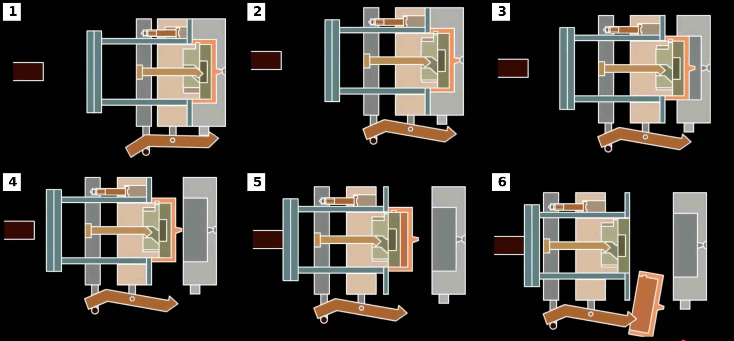
Mechanism 1 – Basic Square Dowel Core Pulling System
The simplest square dowel configuration serves as a direct replacement for the traditional angle pin mechanism.
In this arrangement, the square dowel is mounted in the moving half of the mold and engages a matching slot within the slider assembly.
During mold opening, the dowel moves relative to the slider and converts vertical mold motion into lateral movement.
The slider withdraws from the molded undercut while remaining accurately guided by wear plates and gib surfaces.
The primary advantage of this configuration is simplicity.
No secondary motion systems are required.
No hydraulic cylinders are needed.
No timing mechanisms are necessary.
Because the square dowel performs both driving and guiding functions, the mechanism remains compact and cost-effective.
Design Considerations
The designer must carefully evaluate:
- Core-pulling distance
- Slider mass
- Expected molding pressures
- Available mold opening stroke
- Lubrication access
The contact surfaces should be hardened and ground to minimize wear.
Common material selections include:
- H13
- 1.2344
- S7
- NAK80 inserts with hardened wear components
Surface hardness typically ranges between 48 and 58 HRC depending on application requirements.
Typical Applications
This mechanism is commonly used in:
- Electrical housings
- Appliance components
- Automotive clips
- Small technical parts
Failure Modes
The most common failures include:
- Insufficient lubrication
- Excessive bearing pressure
- Misalignment
- Galling
- Wear plate deterioration
Proper maintenance can often extend operational life beyond several million cycles.
Mechanism 2 – Multi-Angle Square Dowel System
The multi-angle square dowel system introduces additional flexibility by incorporating multiple slopes along the dowel profile.
This design addresses a common engineering challenge.
The highest extraction force is required at the beginning of slider movement when:
- Plastic shrinkage is greatest
- Friction is highest
- Core engagement is maximum
After initial movement begins, the required force decreases substantially.
The multi-angle square dowel takes advantage of this behavior.
The first section of the dowel operates at a relatively shallow angle.
This provides high mechanical advantage and substantial pulling force.
Once the slider has moved beyond the critical extraction zone, a second steeper angle engages.
This increases travel rate and reduces required mold opening distance.
The result is an optimized force profile throughout the entire motion cycle.
Engineering Benefits
Compared with a single-angle design, the multi-angle configuration offers:
- Higher initial extraction force
- Shorter mold opening stroke
- Improved machine utilization
- Better energy efficiency
- Greater design flexibility
Manufacturing Considerations
Precision machining becomes significantly more important.
The transition between angles must be carefully blended to avoid impact loading.
Abrupt transitions can create:
- Shock loads
- Surface damage
- Noise
- Accelerated wear
Modern CNC grinding techniques are often used to achieve the required geometry.
Typical Applications
- Deep undercuts
- Large automotive components
- Structural housings
- Technical industrial products
Mechanism 3 – Delayed Engagement Square Dowel System
In some molded products, immediate side-core withdrawal is undesirable.
Part shrinkage characteristics may create substantial extraction forces immediately after mold opening begins.
To solve this issue, designers employ delayed engagement mechanisms.
In this configuration, the square dowel initially remains disengaged from the slider.
A predetermined mold opening distance occurs before contact is established.
This creates an idle stroke.
During this period:
- Internal cavity pressure dissipates
- Plastic shrinkage stabilizes
- Stress concentrations decrease
- Product deformation risk is reduced
Only after the programmed opening distance has been achieved does the square dowel engage the slider.
The resulting extraction forces are often significantly lower than those experienced in conventional systems.
Advantages
The delayed engagement approach provides:
- Lower extraction forces
- Improved surface quality
- Reduced wear
- Better dimensional consistency
- Increased mold life
Design Challenges
The designer must carefully determine:
- Delay distance
- Product shrinkage behavior
- Material characteristics
- Core geometry
- Mold opening sequence
Too little delay provides minimal benefit.
Too much delay may interfere with subsequent mold operations.
Typical Applications
Delayed engagement systems are commonly found in:
- Cosmetic automotive parts
- Consumer electronics
- Medical housings
- Thin-wall products
- High-gloss molded components
Failure Modes
Potential issues include:
- Incorrect timing
- Premature engagement
- Excessive delay
- Slider impact loading
- Wear at engagement surfaces
When properly engineered, however, delayed engagement square dowel systems can dramatically improve both mold reliability and product quality.
Mechanism 4 – Guide Pin Assisted Square Dowel Core Pulling System
As molded products become larger and side cores become heavier, the designer must carefully consider how loads are transmitted through the mechanism. While a basic square dowel can simultaneously provide motion and guidance, large side actions often benefit from separating these functions.
The Guide Pin Assisted Square Dowel Mechanism accomplishes exactly this objective.
In this design, the square dowel is responsible primarily for generating motion, while dedicated guide pins, guide rails, wear plates, or gib assemblies maintain alignment of the slider throughout the entire stroke.
This separation of duties significantly improves mechanical performance.
Why Guidance Matters
Many engineers underestimate the loads acting on a side core during production.
A typical automotive side core may experience forces generated by:
- Plastic cavity pressure
- Polymer shrinkage
- Mold alignment variations
- Thermal expansion
- Friction within wear plates
- Friction against core surfaces
When all these loads are transmitted through a single driving component, wear increases rapidly.
Even a few hundredths of a millimeter of wear may eventually produce:
- Flash
- Dimensional variation
- Shutoff damage
- Premature maintenance
By introducing guide pins, lateral forces are absorbed independently from the square dowel.
The dowel becomes primarily a driving element rather than a structural bearing component.
Motion Sequence
The operating cycle occurs as follows:
Mold Closed
The slider is fully seated.
Guide pins maintain precise positioning.
The square dowel is fully engaged.
The side core forms the required undercut feature.
Initial Mold Opening
The mold begins opening.
The square dowel starts moving relative to the slider.
Force is transferred through the inclined surfaces.
Slider Movement
The slider moves laterally.
Guide pins maintain alignment.
Wear plates absorb side loading.
The core gradually disengages from the molded part.
Full Core Withdrawal
The required core-pulling distance is achieved.
The molded part is now free of the side undercut.
The mold continues opening until ejection occurs.
Engineering Analysis
One of the greatest benefits of guide-assisted systems is reduction of moment loading.
Without guide pins, any off-center load creates rotational moments on the slider.
These moments generate uneven wear.
The resulting wear pattern often produces:
- Tapered wear plates
- Uneven lubrication
- Slider cocking
- Increased extraction force
Guide systems dramatically reduce these effects.
For large side cores, this may increase mold life by several million cycles.
Design Recommendations
Experienced mold designers generally follow several guidelines:
Guide Pin Diameter
Larger pins improve stiffness but require additional mold space.
Bearing Length
Longer engagement lengths improve stability.
Lubrication Grooves
Lubrication must reach all wear surfaces.
Wear Plate Hardness
Typically 58–62 HRC.
Alignment Tolerance
Guide systems should maintain repeatability within a few microns.
Failure Modes
Common failures include:
- Dry running
- Contaminated lubrication
- Pin bending
- Guide wear
- Misalignment during assembly
Regular inspection of guide components significantly reduces maintenance costs.
Typical Applications
Guide-assisted square dowel systems are commonly used in:
- Automotive bumper molds
- Instrument panel components
- Appliance housings
- Large industrial enclosures
- Multi-cavity production tools
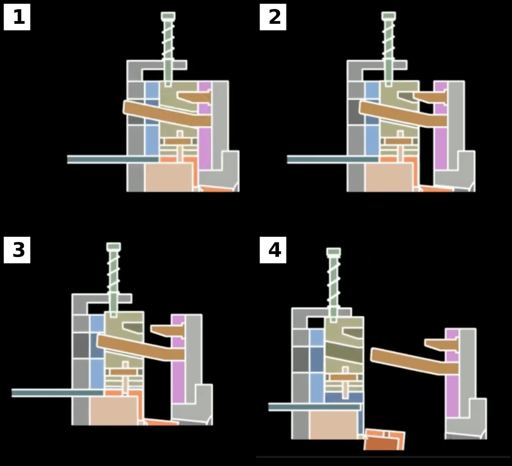
Mechanism 5 – Embedded Square Dowel Core Pulling System
The Embedded Square Dowel Mechanism represents an evolution toward compact and highly integrated mold construction.
Instead of mounting the square dowel externally, the mechanism is fully incorporated into the mold structure itself.
This arrangement protects moving components while maximizing structural rigidity.
Embedded designs are especially valuable in molds where space is limited and side-action travel must be achieved within a compact footprint.
Engineering Objectives
The embedded design serves several important purposes:
- Reduce external hardware
- Improve mold stiffness
- Protect moving components
- Simplify mold handling
- Improve aesthetics of mold construction
Large automotive molds often contain numerous side actions.
External mechanisms can quickly consume available space.
Embedding the square dowel inside the mold body helps maintain a clean and compact design.
Operating Principle
The mechanism typically consists of:
- Embedded square dowel
- Slider body
- Cylindrical transfer pin
- Wear surfaces
- Guide system
As the mold opens, the square dowel engages the transfer pin.
The transfer pin then pushes the slider laterally.
This indirect force transmission allows the driving geometry to remain protected within the mold structure.
Structural Advantages
One of the most important benefits of embedded systems is improved stiffness.
External mechanisms create interruptions in mold structure.
These interruptions reduce rigidity and increase deflection.
An embedded arrangement permits larger uninterrupted steel sections.
This improves:
- Alignment accuracy
- Resistance to cavity pressure
- Long-term dimensional stability
- Surface finish consistency
For precision molds, these benefits can be significant.
Thermal Considerations
Thermal expansion is often overlooked during side-action design.
Every molding cycle introduces heating and cooling.
Temperature gradients cause dimensional changes.
An embedded mechanism experiences a different thermal environment than an external mechanism.
Designers must therefore evaluate:
- Thermal growth
- Lubrication behavior
- Cooling channel placement
- Differential expansion
Failure to account for thermal effects can lead to binding or accelerated wear.
Manufacturing Considerations
Embedded systems require more sophisticated machining.
Typical operations include:
- Deep pocket milling
- Precision grinding
- Internal alignment features
- Close-tolerance fitting
Assembly is generally more complex than conventional square dowel systems.
However, the resulting performance often justifies the additional manufacturing effort.
Maintenance Considerations
The primary disadvantage of embedded systems is accessibility.
Servicing typically requires partial disassembly of the mold.
Designers should therefore incorporate:
- Access covers
- Grease fittings
- Wear inserts
- Replaceable components
Preventive maintenance becomes especially important.
Failure Modes
Common issues include:
Lubrication Failure
Poor lubricant access accelerates wear.
Internal Galling
Steel-on-steel contact becomes problematic.
Transfer Pin Wear
Repeated impact loading damages transfer surfaces.
Thermal Binding
Expansion reduces operating clearance.
Proper design largely eliminates these risks.
Typical Applications
Embedded square dowels are frequently found in:
- High-volume automotive molds
- Consumer electronics
- Precision housings
- Medical device tooling
- Multi-slide molds
Mechanism 6 – Roller-Assisted Internal Core Pulling System with Wedge Reset
Among all square dowel mechanisms, the roller-assisted system represents one of the most sophisticated solutions for internal core pulling.
The design combines:
- Square dowel actuation
- Rolling contact technology
- Internal slider movement
- Automatic wedge-bar resetting
The objective is simple: minimize friction while maximizing reliability.
The Problem with Conventional Sliding Systems
Traditional side actions rely on sliding contact.
Whenever two hardened steel surfaces move against one another, friction is generated.
Friction creates several undesirable effects:
- Heat generation
- Wear
- Increased extraction force
- Lubrication dependency
- Reduced service life
These effects become increasingly problematic as:
- Side cores become larger
- Travel distances increase
- Production volumes rise
The roller-assisted mechanism addresses these limitations directly.
Roller Contact Principle
Instead of sliding along a wear surface, the square dowel drives a roller.
The roller converts sliding friction into rolling friction.
The difference is dramatic.
Rolling friction is often only a small fraction of sliding friction.
This reduces the force required to withdraw the core.
As a result:
- Mold opening loads decrease
- Wear decreases
- Service life increases
Operating Sequence
Mold Closed
The internal core is fully engaged.
The roller rests against the square dowel.
The wedge bar is positioned for reset.
Initial Opening
The mold begins opening.
The square dowel contacts the roller.
Rolling motion begins.
Core Withdrawal
The roller transfers force to the slider.
The slider moves laterally.
The internal undercut is released.
Full Withdrawal
The core reaches its fully retracted position.
The molded part is free.
Mold Closing
The wedge bar engages the roller system.
The slider is forced back into molding position.
The mechanism automatically resets.
Friction Analysis
For engineers, the greatest advantage of roller-assisted systems is reduced friction.
A conventional sliding system may require substantially higher extraction forces.
By replacing sliding contact with rolling contact:
- Force requirements decrease
- Surface temperatures decrease
- Lubricant life increases
This becomes particularly valuable in high-cavitation production molds.
Wear Characteristics
Wear is distributed differently in roller systems.
Instead of large wear areas, stress becomes concentrated within bearing components.
Therefore designers must carefully select:
Roller Material
Typically hardened tool steel.
Bearing Type
Needle bearings or hardened bushings.
Surface Hardness
Generally above 58 HRC.
Lubrication System
Grease reservoirs are often incorporated.
Wedge Bar Reset System
A key feature of this mechanism is automatic resetting.
Without a reset mechanism, the slider would remain in its withdrawn position.
The wedge bar provides positive repositioning.
Advantages include:
- Reliable operation
- Precise positioning
- Reduced setup time
- Improved repeatability
The wedge geometry must be carefully designed to avoid impact loading during mold closure.
Engineering Benefits
Compared with conventional systems, roller-assisted mechanisms offer:
- Lower friction
- Reduced wear
- Higher reliability
- Improved cycle consistency
- Longer service life
These benefits become increasingly important as production volumes approach millions of cycles.
Typical Applications
Roller-assisted square dowel systems are frequently used for:
- Deep internal undercuts
- Technical engineering components
- Pneumatic fittings
- Automotive connectors
- Medical devices
- High-volume production molds
Failure Modes
Although highly reliable, failures can still occur.
Common issues include:
- Bearing failure
- Contamination ingress
- Roller seizure
- Lubrication starvation
- Wedge impact damage
Routine inspection and preventive maintenance are essential for maximizing service life.
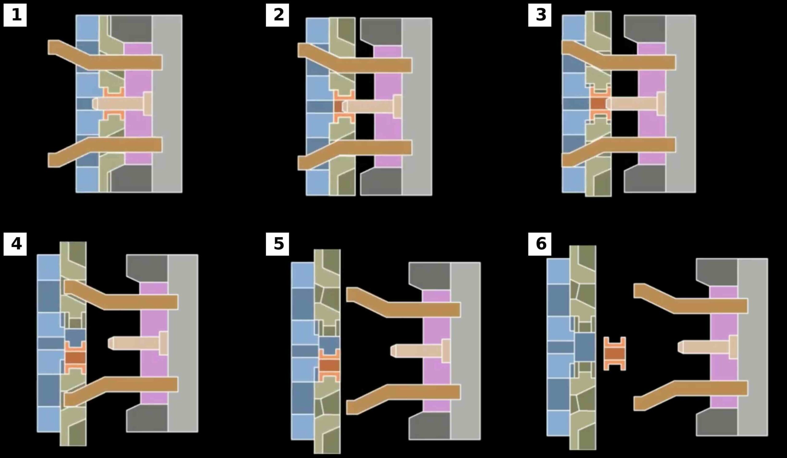
Mechanism 7 – Two-Stage Sequential Square Dowel Core Pulling System
As product geometries become increasingly sophisticated, a single slider movement is often insufficient to release all undercuts safely. Modern automotive connectors, fluid control components, electrical housings, and medical devices frequently contain multiple side features that must be withdrawn in a precise sequence.
The Two-Stage Sequential Square Dowel Mechanism was developed specifically to address these challenges.
Unlike conventional side-action systems, which perform a single extraction movement, this design divides the core-pulling process into two independent stages. Each stage is activated at a predetermined point during mold opening, allowing complex undercuts to be released progressively rather than simultaneously.
This approach significantly improves demolding reliability while reducing stress on both the molded component and the mold mechanism itself.
Why Sequential Core Pulling Is Necessary
Imagine a molded component containing:
- An external side hole
- An internal locking feature
- A secondary undercut behind the first feature
If all side cores attempt to move simultaneously, mechanical interference may occur.
Potential consequences include:
- Product deformation
- Core breakage
- Slider collision
- Increased extraction force
- Poor dimensional stability
By dividing the extraction sequence into multiple stages, each undercut can be released at the optimal moment.
Mechanical Layout
A typical two-stage system contains:
- Primary square dowel
- Outer slider
- Inner slider
- Stop screw
- Timing feature
- Guide system
- Wear surfaces
The outer slider is connected directly to the square dowel.
The inner slider remains inactive during the first portion of the mold opening cycle.
Only after a predetermined distance does the second movement begin.
Motion Sequence
Stage 1 – Initial Extraction
As the mold opens, the square dowel engages the outer slider.
The outer slider retracts first.
This movement typically releases the most accessible or least constrained undercut.
During this stage, the inner slider remains stationary.
Stage 2 – Transfer of Motion
Once the outer slider reaches a specified position, a stop screw or timing mechanism engages.
The motion path changes.
Force is transferred to the second slider.
Stage 3 – Secondary Extraction
The inner slider begins moving.
The second undercut is released.
Because the first undercut has already been cleared, interference is eliminated.
The molded component can now be safely removed.
Engineering Benefits
Sequential extraction provides several important advantages.
Reduced Extraction Force
Only one undercut is released at a time.
Peak forces are reduced.
Improved Reliability
Complex geometries can be demolded safely.
Reduced Wear
Load is distributed throughout the opening cycle.
Improved Product Quality
Reduced deformation produces tighter dimensional control.
Timing Design Considerations
The most critical design parameter is timing.
The engineer must determine:
- First-stage travel distance
- Delay before second activation
- Available mold opening stroke
- Required clearances
Incorrect timing can cause:
- Core interference
- Product damage
- Slider collision
Simulation software is often used to validate motion sequences before manufacturing.
Structural Design Considerations
Sequential systems generally experience higher complexity than conventional side actions.
Designers should evaluate:
Stop Screw Strength
Repeated impact loading can cause fatigue.
Wear Surfaces
Additional moving components increase wear locations.
Lubrication Access
Every moving interface requires lubrication.
Alignment
Both sliders must remain precisely guided.
Typical Applications
Two-stage systems are commonly used for:
- Automotive electrical connectors
- Sensor housings
- Pneumatic components
- Medical devices
- Technical engineering parts
These applications often contain undercuts that cannot be released through a single motion.
Common Failure Modes
Typical issues include:
- Stop screw wear
- Timing drift
- Slider misalignment
- Excessive backlash
- Impact damage
Proper preventive maintenance is essential for long-term performance.
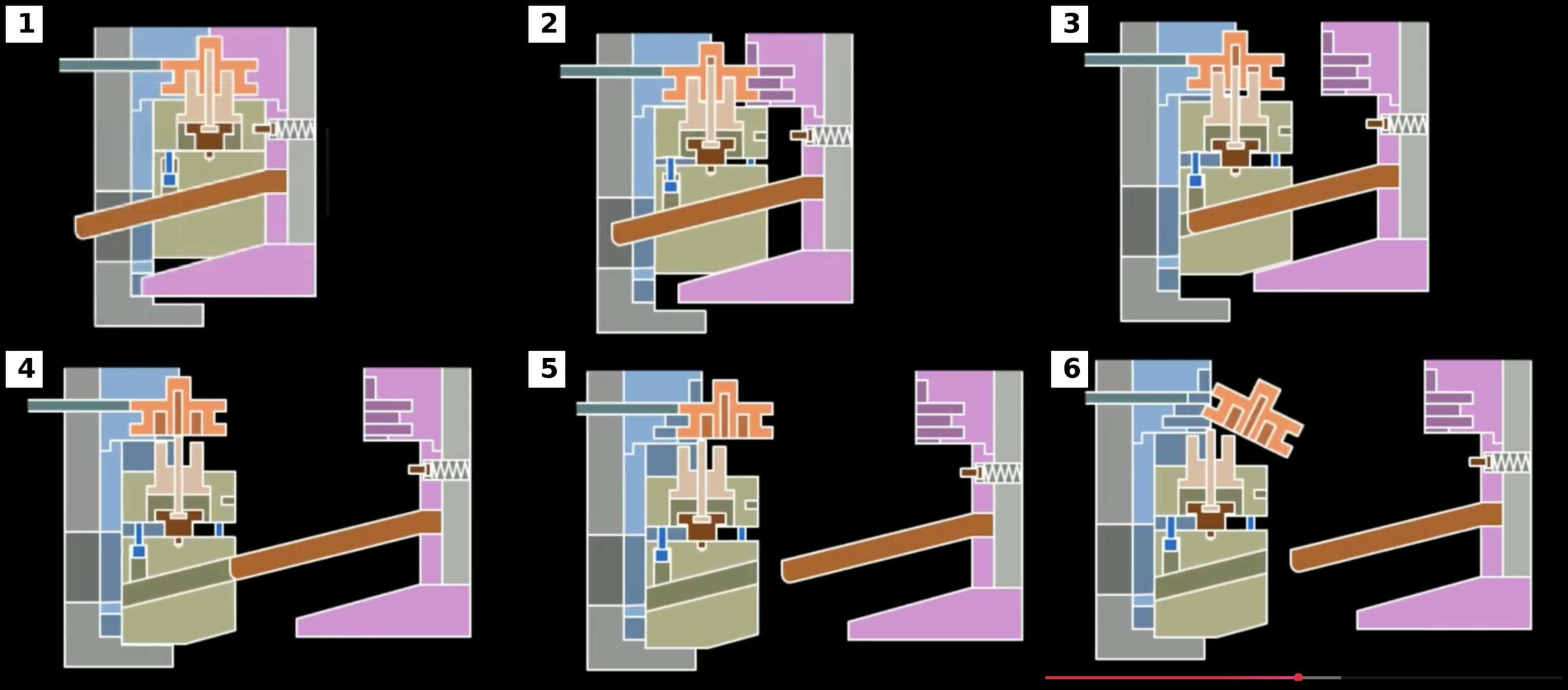
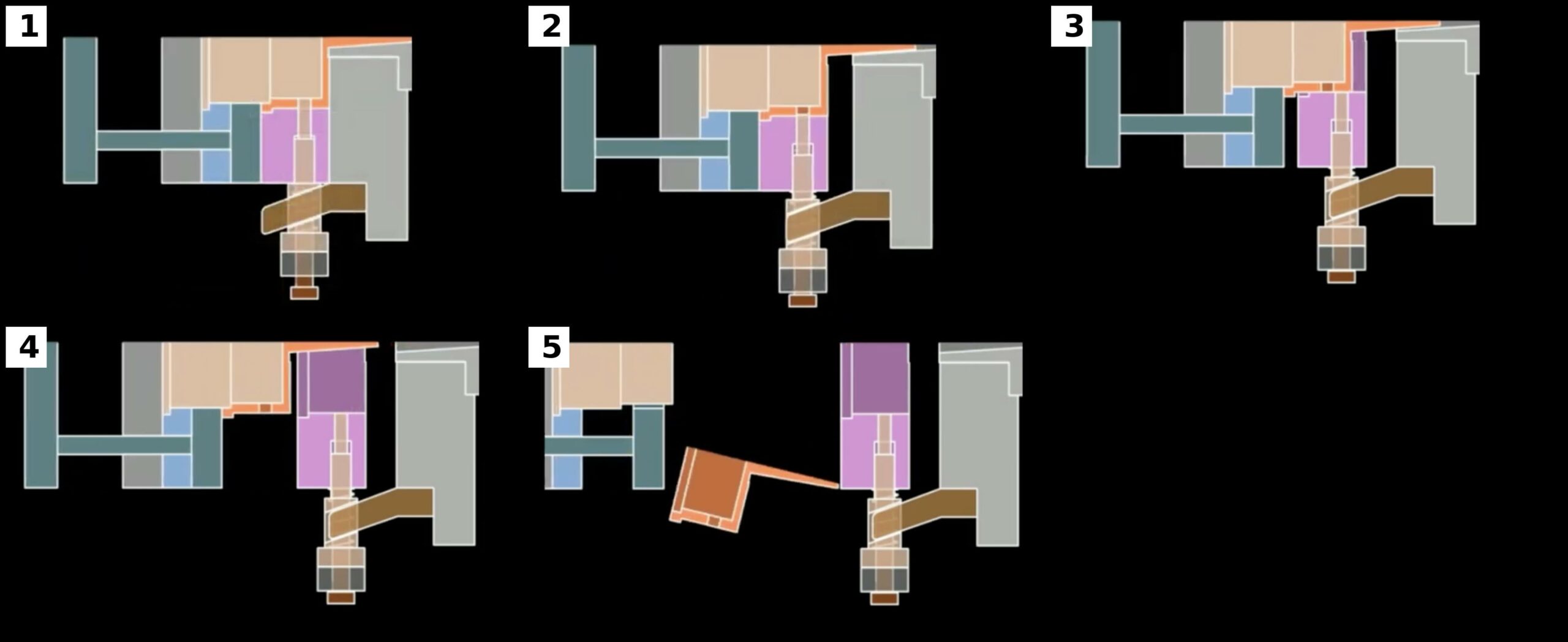
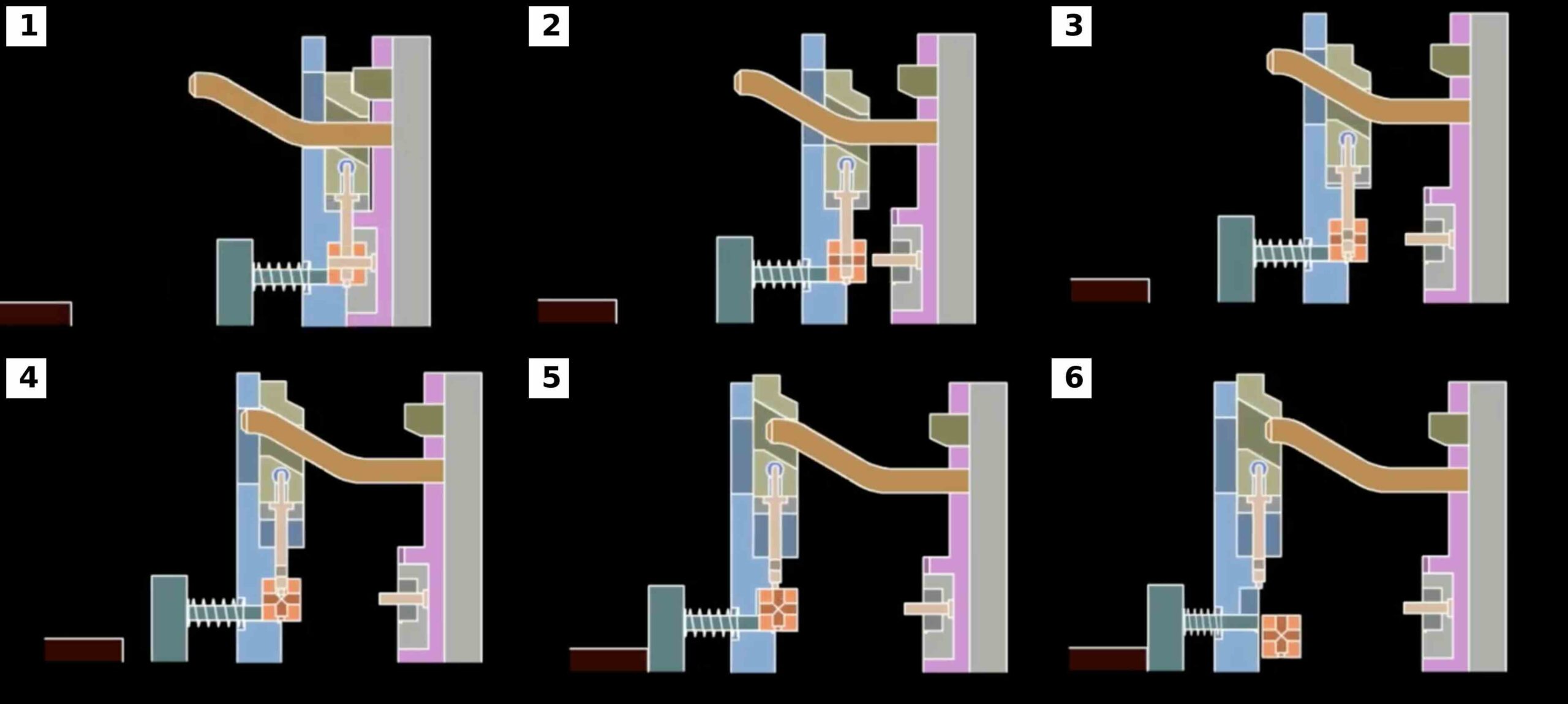
Mechanism 8 – Fixed-Side Spring-Loaded Square Dowel Core Pulling System
Most side-action systems are located on the moving half of the mold.
This arrangement is preferred because the molded component typically remains on the moving side after mold opening.
However, certain products require side cores to be located within the fixed half of the mold.
Examples include:
- Deep cosmetic surfaces
- Hot runner applications
- Fixed-side cavity retention designs
- Specialized packaging molds
In these situations, extracting the side core becomes significantly more challenging.
The Fixed-Side Spring-Loaded Square Dowel Mechanism provides an elegant solution.
The Engineering Challenge
When the mold opens, the fixed half remains attached to the stationary platen.
No natural movement exists to actuate a side core located within the fixed cavity.
A secondary mechanism must therefore create relative motion before the primary mold opening sequence begins.
This is accomplished using spring-loaded plates.
Operating Principle
The mechanism generally consists of:
- Compression springs
- Floating plate
- Square dowel
- Slider
- Travel stop
During mold opening, the springs create an initial separation movement.
This movement actuates the square dowel.
The side core retracts before the primary parting line opens.
Once extraction is complete, the mold proceeds through its normal opening sequence.
Motion Sequence
Mold Closed
The springs are compressed.
The slider remains fully engaged.
The side core forms the required feature.
Initial Opening
The molding machine begins opening.
The springs push the floating plate.
A small opening movement occurs.
The square dowel begins driving the slider.
Core Pulling
The slider retracts.
The undercut is released.
The side core clears the molded part.
Main Parting Line Opening
After core withdrawal is complete, the primary mold opening begins.
The molded component transfers to the moving side.
Normal ejection can occur.
Spring Selection
Spring design is one of the most critical engineering considerations.
The spring force must be sufficient to:
- Move the floating plate
- Overcome friction
- Drive the square dowel
However, excessive spring force creates:
- Higher wear
- Impact loading
- Reduced spring life
Designers must carefully balance these requirements.
Fatigue Life Considerations
Injection molds may operate for millions of cycles.
The springs therefore function as fatigue-loaded components.
Engineers should evaluate:
- Maximum compression
- Working stroke
- Stress levels
- Operating temperature
Conservative spring design dramatically improves reliability.
Advantages
Compact Design
No hydraulic cylinders are required.
Automatic Operation
The system functions entirely through mold movement.
Low Maintenance
Few active components exist.
Cost Effectiveness
Mechanical systems remain less expensive than hydraulic alternatives.
Design Challenges
Potential concerns include:
- Spring fatigue
- Limited available stroke
- Space constraints
- Load variation
These issues must be addressed during design.
Typical Applications
Fixed-side spring-loaded systems are commonly found in:
- Cosmetic housings
- Packaging molds
- Appliance components
- Thin-wall products
- Hot runner tools
Failure Modes
Common failures include:
- Spring breakage
- Uneven spring loading
- Floating plate wear
- Loss of preload
Proper spring selection is therefore essential.
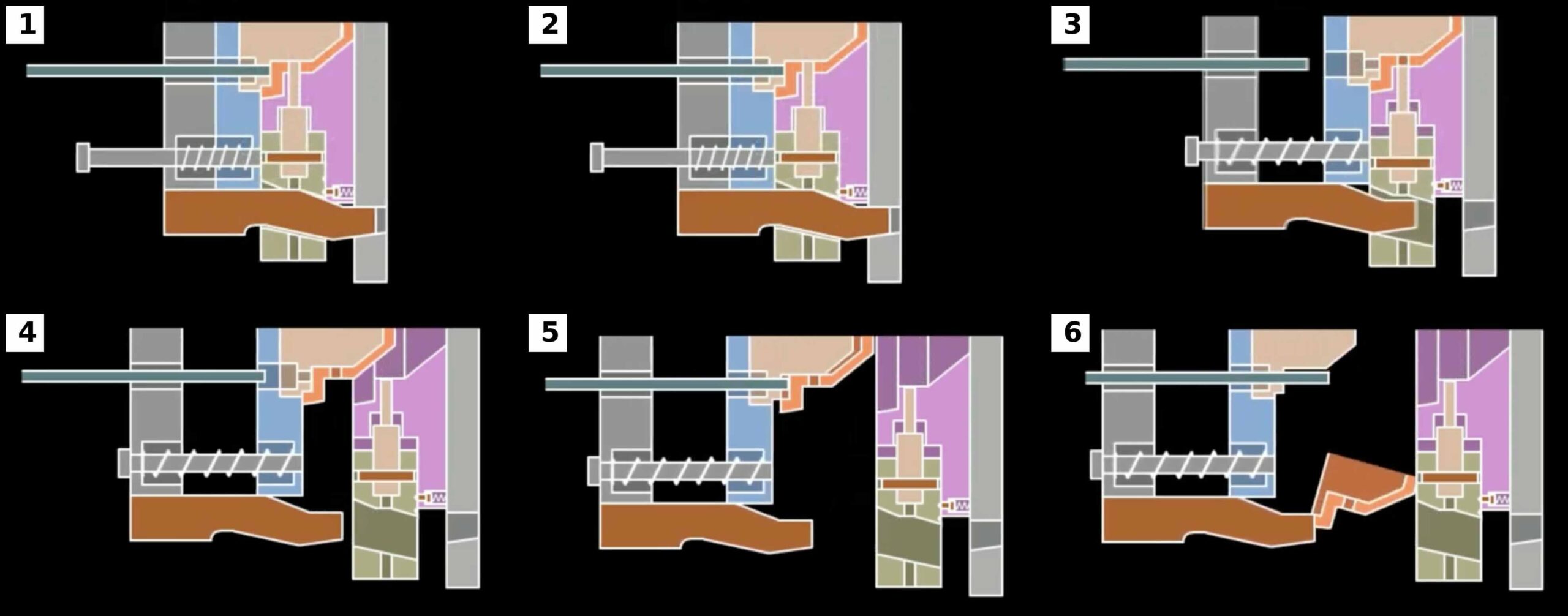
Mechanism 9 – Variable-Angle Square Dowel Core Pulling System
The Variable-Angle Square Dowel Mechanism represents one of the most advanced purely mechanical side-action systems used in injection mold design.
It was developed to solve a fundamental engineering problem:
The force required to initiate slider movement is usually much greater than the force required to continue movement.
Traditional square dowels use a constant angle.
This creates a compromise.
If the angle is small:
- Pulling force is high.
- Travel distance is limited.
If the angle is large:
- Travel distance is excellent.
- Pulling force decreases.
The variable-angle system eliminates this compromise.
Fundamental Mechanical Principle
A variable-angle dowel incorporates two or more operating angles along its length.
Each section performs a specific function.
The first section provides maximum extraction force.
The second section provides maximum travel efficiency.
Together they create an optimized motion profile.
Initial Force Generation
At the beginning of mold opening:
- Plastic shrinkage is greatest.
- Friction is highest.
- Core engagement is maximum.
The dowel therefore uses a relatively shallow angle.
This increases mechanical advantage.
Large pulling forces become available.
The side core begins moving safely.
Transition Zone
Once initial movement has occurred, extraction force requirements decrease dramatically.
The dowel transitions to a steeper angle.
This transition must be carefully engineered.
Abrupt changes can create:
- Impact loading
- Noise
- Accelerated wear
Smooth transitions are preferred.
High-Travel Section
After the transition, the slider moves under the influence of a larger angle.
The larger angle provides:
- Faster slider travel
- Reduced mold opening requirements
- More efficient machine utilization
This stage allows long undercuts to be released without requiring excessively large molding machines.
Mechanical Advantage Analysis
The variable-angle system effectively provides two different mechanisms within a single component.
Force Phase
High mechanical advantage.
Maximum extraction capability.
Travel Phase
Reduced mechanical advantage.
Maximum motion efficiency.
The result is superior overall performance.
Advantages Compared with Standard Square Dowels
Higher Initial Pulling Force
Deep undercuts can be released safely.
Reduced Machine Stroke Requirements
Smaller molding machines may be used.
Improved Efficiency
Motion is optimized throughout the cycle.
Reduced Wear
Forces are distributed more effectively.
Manufacturing Considerations
Variable-angle dowels require:
- Precision CNC machining
- Precision grinding
- Careful inspection
The transition geometry is especially important.
Small errors may significantly alter motion characteristics.
Wear Analysis
The highest contact pressure occurs near the shallow-angle section.
Designers often incorporate:
- Hardened inserts
- Surface coatings
- Wear plates
Common surface treatments include:
- Nitriding
- PVD coatings
- DLC coatings
These treatments improve durability.
Typical Applications
Variable-angle systems are widely used in:
- Automotive bumpers
- Instrument panels
- Large housings
- Industrial enclosures
- Deep side-core applications
Whenever both high force and long travel are required, this design becomes highly attractive.
Common Failure Modes
Potential issues include:
Transition Wear
The angle transition experiences concentrated loading.
Lubrication Failure
Large contact surfaces require proper lubrication.
Manufacturing Errors
Geometry deviations affect performance.
Surface Fatigue
Repeated loading eventually creates wear damage.
Regular inspection minimizes these risks.
Why Many Experts Consider This the Most Efficient Mechanical Side Action
Among purely mechanical side-action systems, the variable-angle square dowel often delivers the best balance between:
- Force
- Travel
- Reliability
- Compactness
- Cost
For this reason it is increasingly common in high-end production tooling where hydraulic systems are undesirable but demanding side-action requirements still exist.
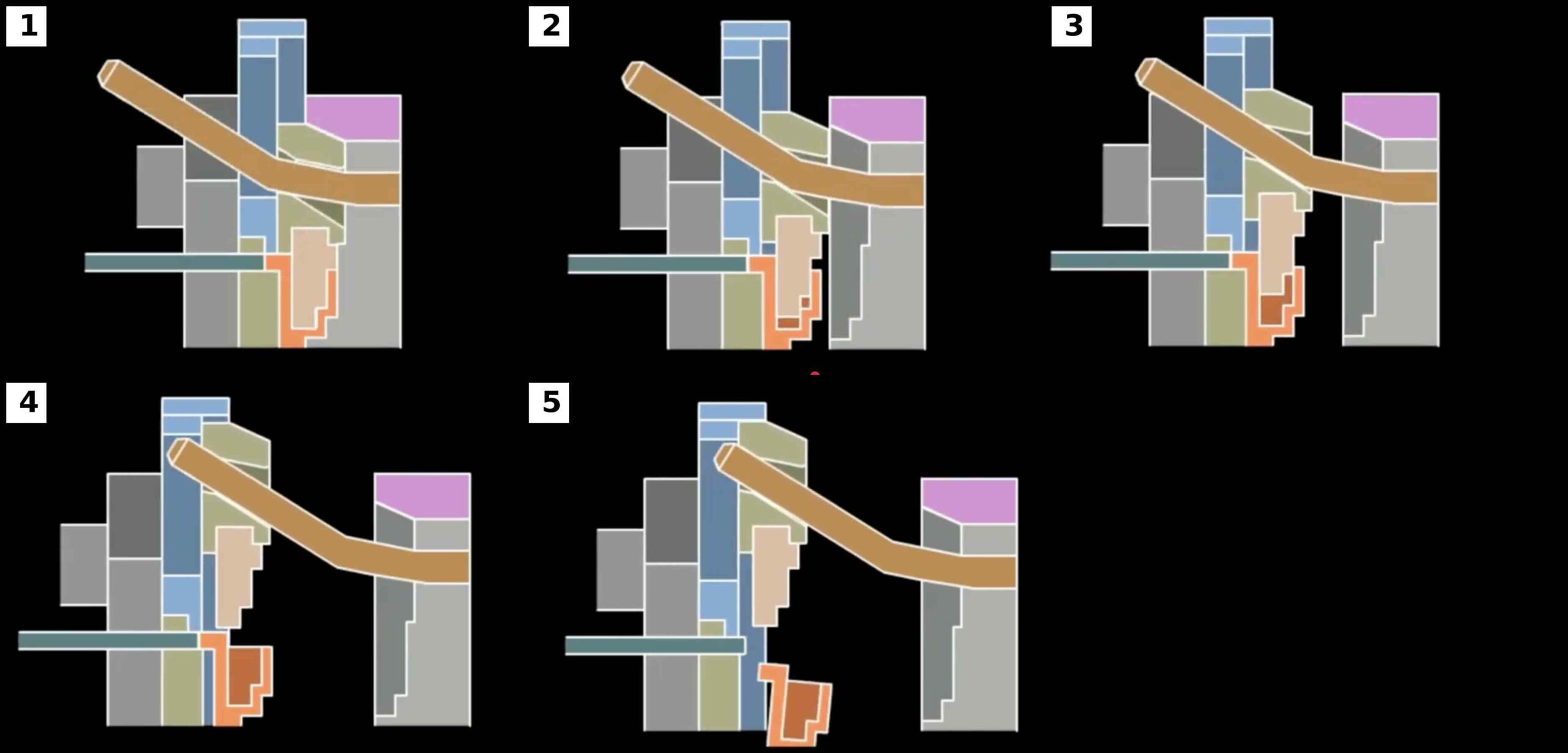
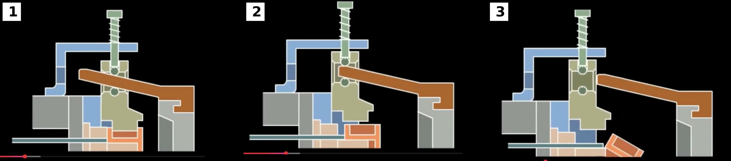
Mechanism 10 – Internal Square Dowel Core Pulling System
Internal undercuts are among the most difficult features to release in injection molding. Unlike external side cores, which can usually move outward with relatively few restrictions, internal undercuts often require movement within a confined space while maintaining structural rigidity and dimensional accuracy.
The Internal Square Dowel Core Pulling Mechanism provides an elegant solution by placing the slider and core-pulling assembly entirely within the mold structure.
This design is commonly used when molded components contain:
- Internal locking features
- Internal grooves
- Pipe threads
- Snap-fit details
- Fluid passages
- Pneumatic connections
Unlike conventional side-action systems, the mechanism operates within the mold stack itself, allowing undercuts to be released before complete mold opening.
Engineering Challenges of Internal Core Pulling
Internal side actions must overcome several difficulties:
Limited Space
The mechanism must fit within the mold structure without interfering with cooling channels, ejector systems, or cavity inserts.
Higher Friction
Internal components often experience greater contact pressure due to polymer shrinkage.
Accessibility
Maintenance access is more restricted.
Cooling Constraints
Space occupied by the mechanism often competes with cooling circuit placement.
As a result, internal core-pulling systems require more careful engineering than external sliders.
Operating Sequence
Mold Closed
The internal slider is fully engaged.
The undercut feature is formed.
The square dowel is positioned for actuation.
Initial Mold Opening
The mold begins opening.
A floating plate or intermediate plate separates first.
Core Pulling
The square dowel engages the internal slider.
The slider retracts.
The internal undercut is released.
Full Mold Opening
Once the undercut is cleared, normal mold opening continues.
Ejection
The molded component is ejected without interference.
Structural Design Considerations
The designer must evaluate:
- Available mold thickness
- Core strength
- Cooling requirements
- Slider guidance
- Lubrication access
Finite element analysis is often used to evaluate stress concentrations in the internal slider assembly.
Advantages
- Excellent solution for internal undercuts
- Compact arrangement
- Fully mechanical operation
- Reliable repeatability
Typical Applications
- Pneumatic fittings
- Medical connectors
- Pipe fittings
- Fluid control devices
- Technical engineering components
Common Failure Modes
- Internal galling
- Lubrication failure
- Thermal expansion binding
- Core cracking
Careful material selection significantly improves durability.
Mechanism 11 – Delayed Parting Square Dowel System – Type 1
Delayed parting systems are designed to control the order in which mold movements occur.
In many products, releasing the side core immediately after mold opening is undesirable. The molded component may still be tightly engaged with the primary core or may not yet be sufficiently supported.
The delayed parting square dowel system introduces a controlled waiting period before side-core extraction begins.
This sequencing improves both product quality and mold reliability.
Why Delayed Parting Is Necessary
Certain molded components experience:
- Significant shrinkage
- High extraction forces
- Delicate cosmetic surfaces
- Thin wall sections
Immediate side-core movement may deform the product.
Delayed parting eliminates this risk.
Operating Principle
The mold contains:
- Main parting line
- Delayed opening mechanism
- Square dowel assembly
- Slider system
The delayed mechanism prevents immediate engagement of the square dowel.
Only after a predetermined opening distance does side-core extraction begin.
Motion Sequence
Stage 1
The mold opens.
The product remains supported.
No side-core movement occurs.
Stage 2
The delayed mechanism reaches its activation point.
The square dowel engages.
Stage 3
The slider retracts.
The undercut is released.
Stage 4
Normal mold opening and ejection continue.
Product Protection Benefits
One of the primary reasons for using delayed parting is product protection.
Benefits include:
- Reduced stress concentration
- Lower deformation risk
- Improved cosmetic quality
- Better dimensional stability
These advantages become increasingly important in precision molding applications.
Engineering Considerations
Critical parameters include:
- Delay distance
- Product shrinkage
- Mold opening speed
- Slider travel distance
Incorrect timing may reduce effectiveness.
Typical Applications
- Thin-wall housings
- Consumer electronics
- Cosmetic automotive components
- Medical products
Failure Modes
Common issues include:
- Timing wear
- Delay mechanism fatigue
- Misalignment
- Impact loading
Regular maintenance ensures long-term reliability.
Mechanism 12 – Delayed Parting Square Dowel System – Type 2
Type 2 delayed parting mechanisms represent a more sophisticated evolution of the previous design.
Rather than simply delaying side-core extraction, this system actively controls the sequence in which the molded component separates from different mold features.
This approach is particularly useful when delicate geometries are present.
Engineering Objective
The goal is to ensure that the molded component is released from the primary core before side-core withdrawal begins.
This reduces:
- Stress concentration
- Product distortion
- Cosmetic defects
- Dimensional variation
Motion Sequence
Primary Release
The molded component first separates from the main core.
The product stabilizes.
Controlled Delay
A predetermined opening movement occurs.
The side core remains engaged.
Secondary Release
The square dowel activates.
The side core retracts.
The remaining undercut is released.
Final Ejection
The product is ejected normally.
Advantages
Compared with Type 1 systems, Type 2 designs provide:
- Better stress control
- Improved dimensional accuracy
- Enhanced cosmetic quality
- Superior process consistency
Applications
Frequently used for:
- Medical components
- Optical housings
- Electronic connectors
- Precision engineering products
These products often require exceptional dimensional control.
Failure Modes
Potential issues include:
- Timing drift
- Wear of delay surfaces
- Excessive clearances
- Sequence disruption
Preventive maintenance remains essential.
Design Calculations for Square Dowel Systems
Professional mold design requires engineering calculations rather than relying solely on experience.
Core Pulling Force
The required pulling force depends on:
- Shrinkage forces
- Friction forces
- Slider weight
- Mold geometry
Designers should always apply adequate safety factors.
For production molds, safety factors between 1.5 and 2.5 are commonly used.
Bearing Pressure
Bearing pressure must remain within acceptable limits.
Excessive pressure leads to:
- Wear
- Galling
- Surface deformation
The larger contact area of square dowels significantly reduces bearing pressure compared with angle pins.
Slider Deflection
Large sliders should be checked for:
- Bending
- Torsion
- Surface distortion
Deflection can affect shutoff integrity and product quality.
Wear Surface Analysis
Engineers should evaluate:
- Surface hardness
- Contact area
- Lubrication quality
- Cycle count
Expected wear rates influence maintenance schedules.
Material Selection
Material selection is one of the most important aspects of square dowel design.
Square Dowels
Common materials include:
- H13
- 1.2344
- S7
- 1.2367
These materials offer:
- High toughness
- Wear resistance
- Heat-treatment capability
Sliders
Common choices include:
- P20
- 1.2738
- H13
- NAK80
Material selection depends on:
- Production volume
- Resin type
- Required hardness
Wear Components
Wear plates frequently utilize:
- Bronze alloys
- Hardened tool steel
- Self-lubricating inserts
These materials reduce friction and extend service life.
Heat Treatment Recommendations
Proper heat treatment dramatically improves durability.
Typical hardness ranges:
| Component | Hardness |
|---|---|
| Square Dowel | 54–60 HRC |
| Wear Plates | 58–62 HRC |
| Sliders | 48–56 HRC |
| Wedges | 56–60 HRC |
Nitriding is frequently used to increase surface hardness while maintaining core toughness.
Lubrication Engineering
Lubrication is one of the most overlooked aspects of mold reliability.
Without proper lubrication:
- Friction increases
- Wear accelerates
- Galling occurs
- Cycle consistency deteriorates
Lubrication Methods
Grease Grooves
Most common solution.
Graphite Inserts
Suitable for difficult access locations.
Self-Lubricating Wear Plates
Ideal for high-volume molds.
Automatic Lubrication Systems
Used in fully automated production environments.
Common Failure Analysis
Understanding failure modes allows designers to improve future projects.
Galling
Caused by:
- Inadequate lubrication
- Excessive pressure
- Improper material pairing
Wear
Results from:
- High cycle counts
- Poor lubrication
- Contamination
Cracking
Typically caused by:
- Impact loading
- Improper heat treatment
- Stress concentration
Misalignment
Frequently caused by:
- Guide wear
- Assembly errors
- Deflection
Misalignment often becomes the root cause of secondary failures.
Maintenance Strategy
A well-designed square dowel mechanism should be accompanied by a structured maintenance program.
Daily Checks
- Lubrication verification
- Visual inspection
Weekly Checks
- Slider movement
- Wear surface condition
Monthly Checks
- Alignment verification
- Hardware inspection
Annual Maintenance
- Complete disassembly
- Wear measurement
- Component replacement as required
Preventive maintenance is substantially less expensive than emergency repairs.
Best Practices for Modern Mold Design
Experienced mold designers generally follow several principles:
- Minimize friction wherever possible.
- Maximize contact area.
- Use hardened wear surfaces.
- Provide adequate lubrication access.
- Avoid impact loading.
- Design for maintenance.
- Verify motion sequences through simulation.
- Apply conservative safety factors.
- Consider thermal expansion effects.
- Standardize components whenever possible.
These practices consistently improve mold reliability and service life.
Conclusion
Square dowel core pulling mechanisms have become one of the most versatile and reliable solutions for releasing undercuts in modern injection molds. Their ability to combine high load capacity, improved wear resistance, compact packaging, and precise motion control makes them superior to conventional angle pin systems in many demanding applications.
From basic side actions to sophisticated multi-stage and delayed-parting systems, square dowels provide mold designers with exceptional flexibility for solving increasingly complex molding challenges. When combined with proper engineering calculations, material selection, heat treatment, lubrication strategies, and preventive maintenance, these mechanisms can operate reliably for millions of production cycles.
As molded products continue to evolve toward greater complexity and tighter tolerances, square dowel technology will remain a critical element of advanced injection mold design, providing the performance, durability, and precision required by modern manufacturing industries.