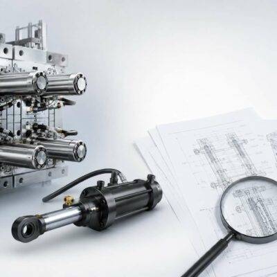
Fundamentals, Operating Principles and Mechanism Overview
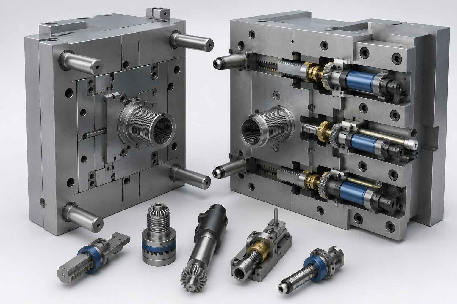
Mechanical unscrewing systems are among the most widely used solutions for producing threaded plastic components in injection molds. Unlike hydraulic or servo-driven systems, mechanical unscrewing mechanisms use gears, racks, mold opening motion, or dedicated drive systems to rotate the threaded core and release the molded component.
For decades, mechanical unscrewing systems have been the preferred solution for high-volume production because they offer an excellent balance between reliability, cost, cycle time, and maintenance requirements.
In this article we will focus on four mechanisms:
- Mechanism 1 – Motor Driven Threaded Core
- Mechanism 2 – Rack and Pinion Unscrewing Type 1
- Mechanism 5 – Rack and Pinion Unscrewing Type 2
- Mechanism 6 – Machine Driven Unscrewing
These four systems represent the majority of mechanical thread release solutions found in production molds.
What Is a Mechanical Unscrewing System?
A mechanical unscrewing system is a mechanism that converts available mechanical energy into rotational movement of a threaded core.
The energy source may be:
- Electric motor
- Mold opening movement
- Machine platen movement
- Mechanical drive system
Unlike hydraulic systems, no hydraulic cylinder is directly responsible for rotating the core.
The primary objective remains the same:
Rotate the threaded core enough turns to completely disengage the molded thread.
Why Mechanical Systems Remain Popular
Despite the availability of modern servo systems, mechanical unscrewing systems remain extremely common.
Reasons include:
- Proven reliability
- Lower maintenance cost
- Simpler troubleshooting
- No hydraulic leakage risk
- Lower operating cost
- Long service life
Many mechanical unscrewing molds continue operating successfully after tens of millions of production cycles.
The Mechanical Power Chain
Every mechanical unscrewing system follows a similar power path.
Power Source
↓
Transmission System
↓
Rotating Shaft
↓
Threaded Core
↓
Plastic Component
The complexity of the transmission system varies depending on the mechanism.
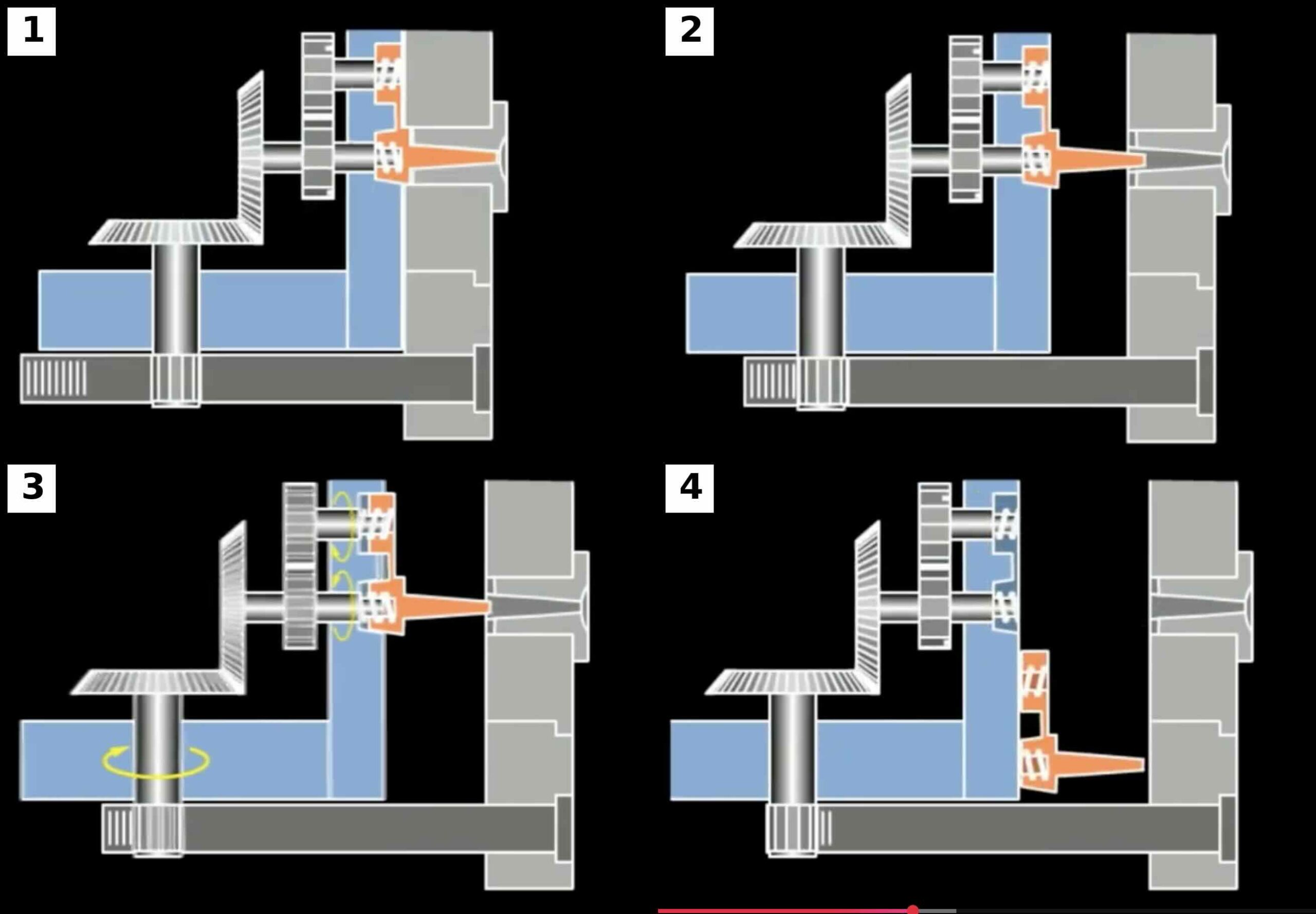
Mechanism 1 – Motor Driven Threaded Core
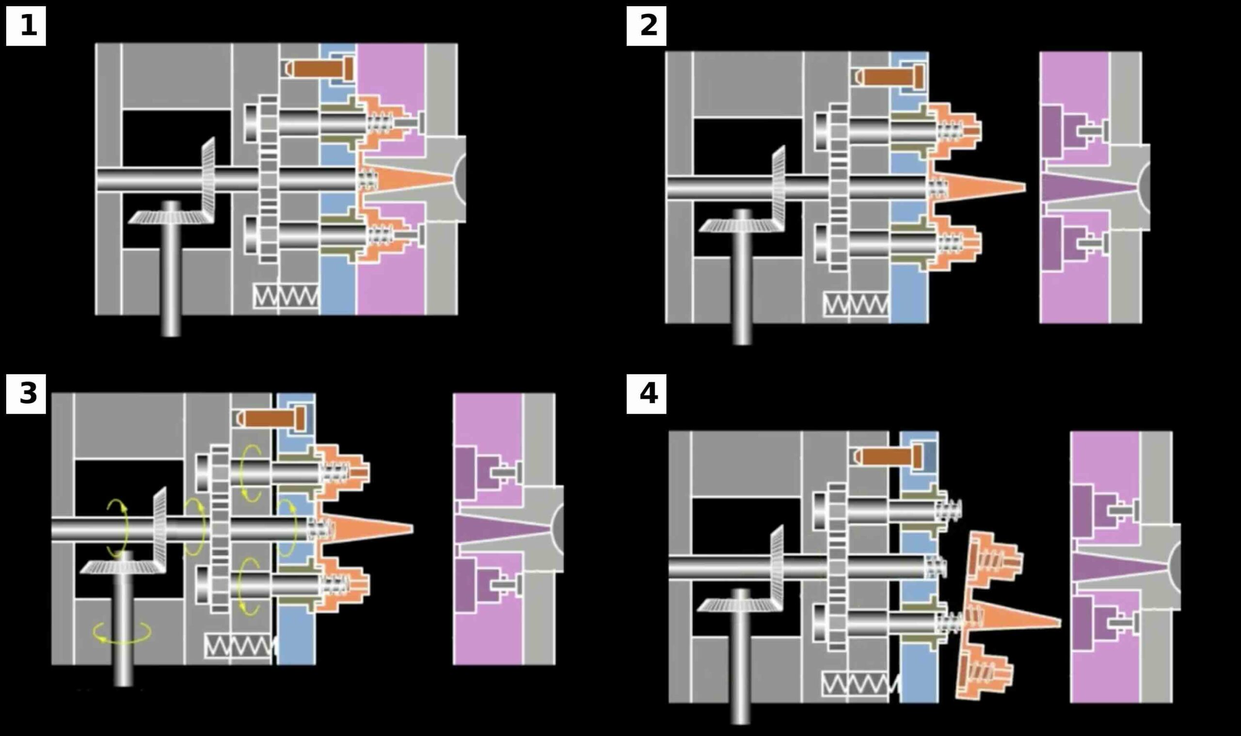
Mechanism 1 is one of the most sophisticated mechanical unscrewing systems.
A dedicated motor rotates the threaded core through a gear transmission system.
When the mold opens:
- The threaded core begins rotating
- The molded component remains stationary
- The thread disengages progressively
- The part is released automatically
Operating Sequence
Step 1
Mold opens.
Step 2
Motor starts rotating the threaded core.
Step 3
The threaded core begins unscrewing.
Step 4
The component moves axially along the thread.
Step 5
The thread completely disengages.
Step 6
The part is ejected.
Advantages
- Fully automatic
- Excellent repeatability
- Suitable for deep threads
- Suitable for fine-pitch threads
- Excellent process control
Limitations
- Higher mold cost
- Additional electrical components
- More complex maintenance
Typical Applications
- Medical closures
- Packaging systems
- Automotive fluid reservoirs
- Industrial threaded components
Mechanism 2 – Rack and Pinion Unscrewing Type 1
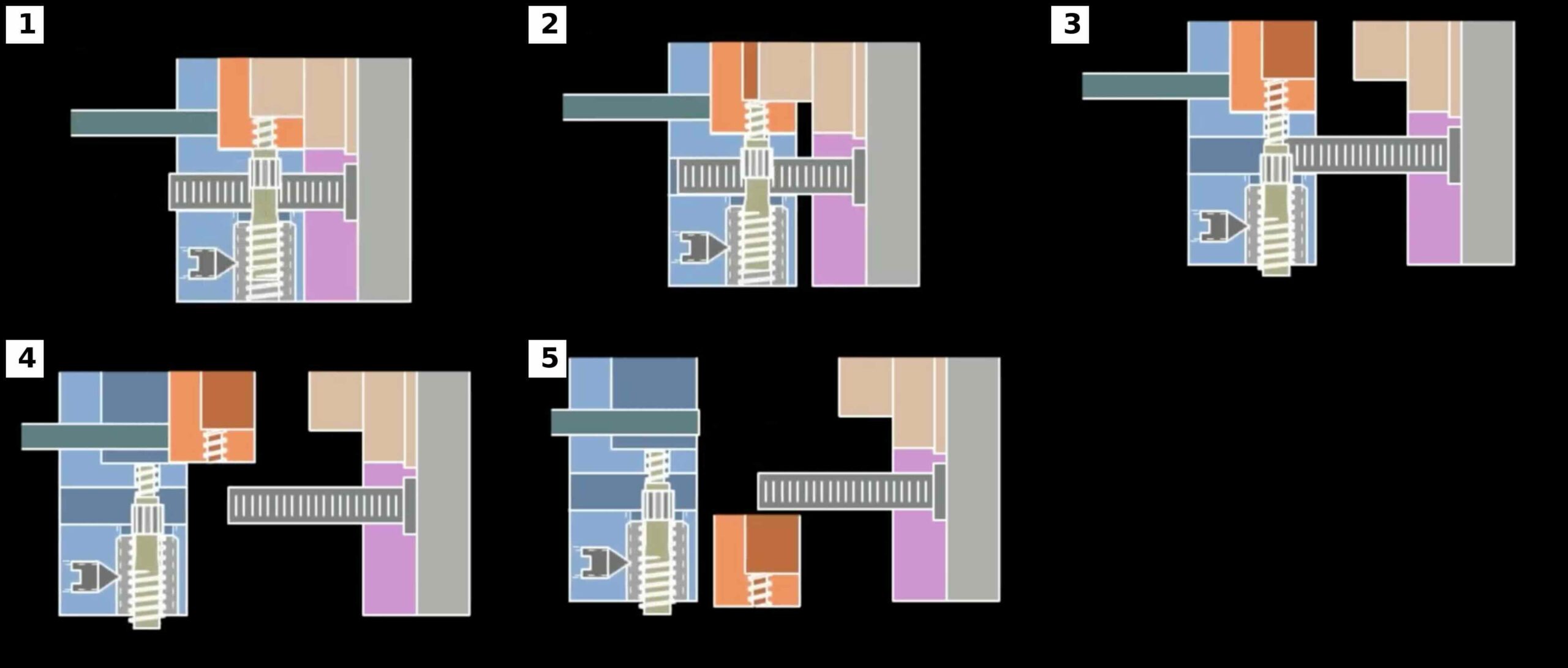
Mechanism 2 converts linear mold movement into rotational motion using a rack and pinion arrangement.
As the mold opens, a rack engages a pinion.
The pinion rotates the threaded core.
This approach eliminates the need for a separate motor.
Operating Sequence
Step 1
Mold begins opening.
Step 2
Rack moves linearly.
Step 3
Rack engages pinion.
Step 4
Pinion rotates threaded core.
Step 5
Thread disengages.
Step 6
Part is released.
Advantages
- Compact design
- Lower cost than motor-driven systems
- Uses mold opening movement
- Proven reliability
Limitations
- Large rack travel may be required
- Gear wear must be monitored
- Speed depends on mold opening motion
Typical Applications
- Industrial caps
- Automotive connectors
- Medium-volume production molds
Mechanism 5 – Rack and Pinion Unscrewing Type 2
Mechanism 5 uses the same fundamental principle as Mechanism 2 but incorporates additional transmission elements.
The system may include:
- Intermediate gears
- Transmission shafts
- Multiple rotating elements
This allows more flexibility in mold layout.
Why Use a More Complex Rack System?
Sometimes the threaded core cannot be positioned directly adjacent to the rack.
Possible reasons include:
- Limited mold space
- Multiple cavities
- Cooling requirements
- Ejection constraints
Intermediate transmission components solve these layout problems.
Advantages
- Greater design flexibility
- Suitable for complex mold layouts
- No dedicated motor required
Limitations
- More moving parts
- Additional wear points
- More difficult assembly
Mechanism 6 – Machine Driven Unscrewing
Mechanism 6 uses the movement of the injection molding machine itself.
Rather than relying on a motor or rack, the opening motion of the machine generates the rotational movement required for thread release.
This design became popular before modern servo systems became widely available.
Operating Sequence
Step 1
Machine opening movement begins.
Step 2
Internal gears rotate.
Step 3
Threaded core rotates.
Step 4
Thread disengages.
Step 5
Part exits cavity.
Advantages
- No dedicated motor
- No hydraulic system
- Uses existing machine motion
Limitations
- Less flexible than motor systems
- More difficult to optimize independently
- Motion tied directly to mold opening sequence
Comparing the Four Mechanical Systems
| Parameter | Mechanism 1 | Mechanism 2 | Mechanism 5 | Mechanism 6 |
|---|---|---|---|---|
| Automation | Excellent | Excellent | Excellent | Excellent |
| Mold Cost | High | Medium | Medium | Medium |
| Maintenance | Medium | Low | Medium | Medium |
| Flexibility | Excellent | Good | Very Good | Good |
| Complexity | High | Medium | High | Medium |
Which Mechanical System Is Best?
There is no universal answer.
The correct choice depends on:
- Production volume
- Thread geometry
- Available mold space
- Budget
- Reliability requirements
However, the following guidelines are useful.
Choose Mechanism 1 when:
- Maximum automation is required
- Thread geometry is demanding
- Cycle time is critical
Choose Mechanism 2 when:
- Simplicity is important
- Mold opening travel is available
- Medium production volumes are expected
Choose Mechanism 5 when:
- Mold layout is complex
- Multiple transmission paths are required
Choose Mechanism 6 when:
- Existing machine motion can be used efficiently
- A dedicated drive system is undesirable
Common Design Objectives
Regardless of which mechanical system is selected, the engineer must achieve:
- Adequate torque
- Correct rotational speed
- Acceptable cycle time
- Long service life
- Easy maintenance
These objectives drive all subsequent calculations.
Engineering Parameters Required
Before sizing any mechanical unscrewing system, the following values must be known:
□ Thread Diameter
□ Thread Pitch
□ Thread Engagement Length
□ Number of Turns
□ Unscrewing Angle
□ Required Torque
□ Design Torque
□ Core Speed
□ Target Cycle Time
These values were introduced in Article 1 and will now be used to dimension the mechanical components.
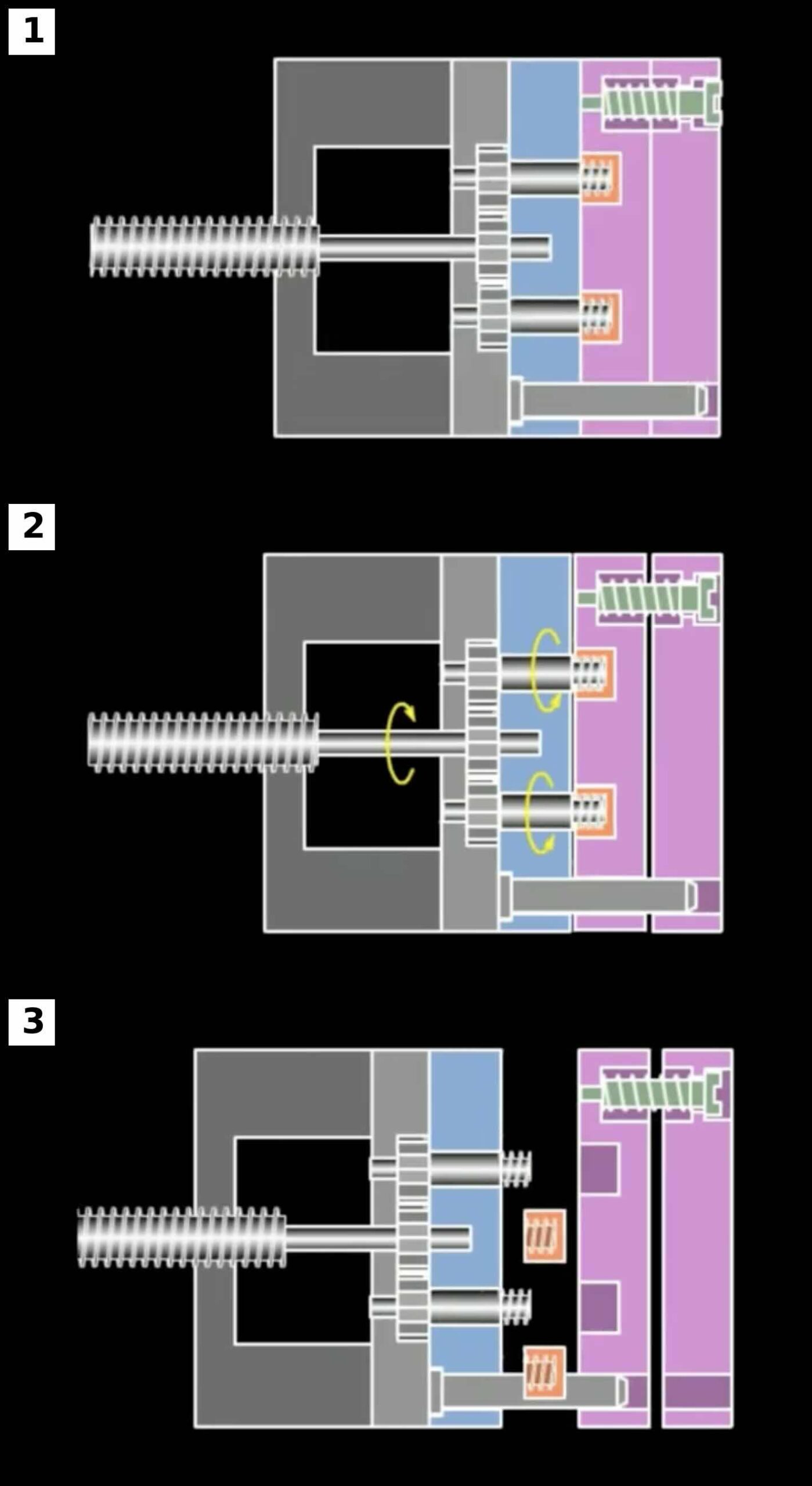
Gear Design, Rack Travel and Torque Transmission
Previously we examined the operating principles of the four most common mechanical unscrewing mechanisms:
- Mechanism 1 – Motor Driven Threaded Core
- Mechanism 2 – Rack and Pinion Type 1
- Mechanism 5 – Rack and Pinion Type 2
- Mechanism 6 – Machine Driven Unscrewing
The next step is transforming thread requirements into a practical mechanical design.
The engineer must determine:
- Gear ratios
- Rack travel
- Gear dimensions
- Torque multiplication
- Mechanical efficiency
- Safety factors
These calculations form the backbone of every mechanical unscrewing system.
Mechanical Design Workflow
The recommended design sequence is:
Step 1
Determine thread geometry.
↓
Step 2
Calculate required turns.
↓
Step 3
Calculate required torque.
↓
Step 4
Select gear ratio.
↓
Step 5
Calculate rack travel.
↓
Step 6
Select gear dimensions.
↓
Step 7
Verify torque transmission.
↓
Step 8
Apply safety factors.
Engineering Example
Throughout this article we will use a common closure application.
Input Data
Thread Diameter = 38 mm
Pitch = 3 mm
Thread Engagement = 12 mm
Required Turns = 4
Calculated Torque = 15 Nm
Safety Factor = 2
Design Torque = 30 Nm
Required Unscrewing Time = 2 seconds
Gear Ratio Selection
Gear ratio determines:
- Output speed
- Output torque
Formula
Gear Ratio = Input Speed / Output Speed
Example
Motor Speed = 1200 RPM
Required Core Speed = 120 RPM
Calculation
Gear Ratio = 1200 / 120
Gear Ratio = 10
Result
Required Gear Ratio = 10:1
Why Gear Reduction Is Important
Injection mold threads rarely require high rotational speed.
Instead, they require:
- Controlled motion
- High torque
- Smooth operation
Gear reduction converts:
High Speed
↓
Lower Speed
Higher Torque
This makes gearboxes ideal for thread release applications.
Torque Multiplication
Gear systems multiply torque.
Formula
Output Torque = Input Torque × Gear Ratio
Example
Motor Torque = 3 Nm
Gear Ratio = 10
Calculation
Output Torque = 3 × 10
Output Torque = 30 Nm
Result
The threaded core receives:
30 Nm
of torque.
Mechanical Efficiency
Real gear systems are not 100 percent efficient.
Losses occur due to:
- Friction
- Lubrication
- Bearing drag
- Misalignment
Typical values:
Spur Gears
95 to 98 percent
Bevel Gears
90 to 95 percent
Complex Gear Trains
85 to 95 percent
Example
Theoretical Torque = 30 Nm
Efficiency = 95 percent
Calculation
Actual Torque = 30 × 0.95
Actual Torque = 28.5 Nm
Result
Actual Available Torque = 28.5 Nm
Always include efficiency losses in design calculations.
Spur Gear Design Fundamentals
Spur gears are the most common gears found in unscrewing systems.
Advantages:
- Easy manufacturing
- High efficiency
- Simple maintenance
- Low cost
Typical applications:
- Motor driven systems
- Rack systems
- Machine driven systems
Pitch Circle Diameter
The pitch circle diameter determines gear size.
Formula
Pitch Circle Diameter = Module × Number of Teeth
Example
Module = 2
Number of Teeth = 40
Calculation
Pitch Circle Diameter = 2 × 40
Pitch Circle Diameter = 80 mm
Result
Gear Pitch Diameter = 80 mm
Gear Tooth Selection
Larger gears provide:
- Higher torque capacity
- Lower tooth stress
- Longer service life
Smaller gears provide:
- Compact design
- Lower weight
A compromise is usually required.
Gear Tangential Force
Gear teeth transmit force.
Formula
Tangential Force = Torque / Radius
Example
Torque = 30 Nm
Pitch Diameter = 80 mm
Radius = 40 mm
Convert Radius
40 mm = 0.04 m
Calculation
Tangential Force = 30 / 0.04
Tangential Force = 750 N
Result
The gear teeth must transmit:
750 N
Rack and Pinion Systems
Mechanisms 2 and 5 rely on rack and pinion systems.
The rack converts linear motion into rotational movement.
This makes use of mold opening movement without requiring a dedicated motor.
Rack Travel Calculation
One revolution requires rack movement equal to the circumference of the pinion.
Formula
Circumference = 3.1416 × Pitch Diameter
Example
Pinion Diameter = 80 mm
Calculation
Circumference = 3.1416 × 80
Circumference = 251.3 mm
Result
One revolution requires:
251.3 mm
of rack travel.
Total Rack Travel
Formula
Rack Travel = Circumference × Number of Turns
Example
Required Turns = 4
Calculation
Rack Travel = 251.3 × 4
Rack Travel = 1005 mm
Result
Required Rack Travel = 1005 mm
This example illustrates a common design challenge.
Large thread engagement often results in excessive rack travel.
Reducing Rack Travel
Possible solutions include:
- Larger thread pitch
- Fewer thread turns
- Alternative gear ratios
- Motor driven systems
Designers should evaluate rack travel early in the project.
Bevel Gears
Mechanism 1 frequently uses bevel gears.
Bevel gears transfer motion between intersecting shafts.
Typical applications:
- 90 degree drive arrangements
- Compact mold layouts
- Space constrained designs
Bevel Gear Advantages
- Efficient power transmission
- Compact packaging
- High torque capability
Bevel Gear Limitations
- More expensive
- More sensitive to alignment
- More difficult manufacturing
Multiple Gear Stages
Some unscrewing systems use multiple reduction stages.
Advantages:
- Higher torque
- Compact design
Disadvantages:
- More components
- More wear points
- Increased backlash
Backlash
Backlash is the clearance between mating gear teeth.
Some backlash is necessary.
Too much backlash causes:
- Impact loading
- Position errors
- Increased wear
Too little backlash causes:
- Heat generation
- Excessive friction
- Premature failure
Proper gear design balances these factors.
Mechanical Design Example
M38 Closure
Input Data
Design Torque = 30 Nm
Required Core Speed = 120 RPM
Motor Speed = 1200 RPM
Step 1
Calculate Gear Ratio
Gear Ratio = 1200 / 120
Gear Ratio = 10
Step 2
Select Gear Set
Driver = 20 Teeth
Driven = 200 Teeth
Gear Ratio = 10
Step 3
Calculate Output Torque
Motor Torque = 3 Nm
Output Torque = 3 × 10
Output Torque = 30 Nm
Step 4
Apply Efficiency
Efficiency = 95 percent
Actual Torque = 30 × 0.95
Actual Torque = 28.5 Nm
Step 5
Verify Design Margin
Required Torque = 15 Nm
Available Torque = 28.5 Nm
Safety Margin = 28.5 / 15
Safety Margin = 1.9
Result
The system is acceptable.
Common Gear Design Mistakes
Mistake 1
Ignoring efficiency losses.
Mistake 2
Selecting gear teeth that are too small.
Mistake 3
Ignoring backlash.
Mistake 4
Underestimating rack travel.
Mistake 5
Failing to consider maintenance access.
Design Checklist
Before finalizing a gear system verify:
□ Required turns calculated
□ Required speed calculated
□ Required torque calculated
□ Gear ratio selected
□ Efficiency considered
□ Gear tooth force calculated
□ Rack travel calculated
□ Backlash verified
□ Maintenance access verified
□ Safety factor applied
Part 3 – Shaft Design, Keys, Splines, Bearings and Reliability
In Part 2 we designed the transmission system.
We calculated:
- Gear ratios
- Torque multiplication
- Rack travel
- Gear forces
- Mechanical efficiency
The next step is ensuring that the mechanical components can survive millions of production cycles.
A gear train is only as reliable as the components that transmit its torque.
This chapter focuses on:
- Shaft design
- Key design
- Splined connections
- Bearing selection
- Fatigue life
- Reliability engineering
These calculations are among the most important in any mechanical unscrewing system.
Why Shaft Design Is Critical
The shaft transfers torque from the transmission system to the threaded core.
Every unscrewing cycle produces:
- Torsional stress
- Bending stress
- Fatigue loading
- Shock loading
A shaft that appears adequate for static loads may fail after several million cycles.
For this reason, shaft design must always consider long-term reliability.
Loads Acting on the Shaft
The shaft experiences three primary loads.
Torsion
Produced by thread release torque.
Bending
Produced by:
- Gear forces
- Rack forces
- Overhung loads
Fatigue
Produced by repeated cycling.
A mold operating continuously may exceed:
10 million cycles
during its service life.
Shaft Material Selection
Common materials include:
C45 Steel
Advantages
- Economical
- Easy machining
- Good strength
Typical Applications
- Standard molds
42CrMo4
Advantages
- High strength
- Good fatigue resistance
Typical Applications
- High production molds
Stainless Steel
Advantages
- Corrosion resistance
Typical Applications
- Medical molds
- Food packaging molds
Torsional Stress Calculation
The first shaft verification is torsional stress.
Formula
Shear Stress =
16 × Torque
/
(3.1416 × Diameter³)
Where:
Torque = Nmm
Diameter = mm
Stress = MPa
Example
Design Torque = 30 Nm
Convert Torque
30 Nm = 30,000 Nmm
Assume Shaft Diameter = 20 mm
Calculation
Shear Stress =
(16 × 30,000)
/
(3.1416 × 20³)
Shear Stress = 19.1 MPa
Result
Torsional Stress = 19.1 MPa
This value is generally acceptable for hardened steel shafts.
Shaft Diameter Estimation
The previous equation can be rearranged.
Formula
Shaft Diameter = Cube Root Of
(16 × Torque)
/
(3.1416 × Allowable Stress)
Example
Torque = 30,000 Nmm
Allowable Stress = 60 MPa
Calculation
Diameter ≈ 13.6 mm
Engineering Practice
Select Next Standard Size
Chosen Diameter = 16 mm
In production molds, designers often increase diameter further to improve rigidity.
Why Rigidity Matters
Many engineers focus only on strength.
However:
Deflection is often more problematic than failure.
Excessive shaft deflection can cause:
- Thread misalignment
- Gear wear
- Bearing overload
- Poor part quality
A larger shaft often improves reliability significantly.
Key Design
Most gears are mounted using keys.
The key transmits torque between:
- Shaft
- Gear hub
A poorly designed key is a common failure point.
Key Force Calculation
Formula
Force = Torque / Radius
Example
Torque = 30 Nm
Shaft Diameter = 20 mm
Radius = 10 mm
Convert Radius
10 mm = 0.01 m
Calculation
Force = 30 / 0.01
Force = 3000 N
Result
Key Force = 3000 N
Key Bearing Stress
Formula
Bearing Stress = Force / Contact Area
Where
Contact Area = Length × Height
Example
Force = 3000 N
Key Length = 40 mm
Key Height = 5 mm
Area = 40 × 5
Area = 200 mm²
Calculation
Bearing Stress = 3000 / 200
Bearing Stress = 15 MPa
Result
Key Bearing Stress = 15 MPa
Key Design Guidelines
For mechanical unscrewing systems:
Recommended Key Length
1.5 to 2 times shaft diameter
Example
20 mm Shaft
Recommended Key Length
30 to 40 mm
This provides a good balance between strength and assembly convenience.
Splined Connections
High-production molds often use splines instead of keys.
Advantages
- Higher torque capacity
- Better load distribution
- Reduced backlash
- Improved fatigue life
Why Splines Are Used
Consider a mold producing:
3 million parts per year
for
10 years
Total Cycles
30 million
At these cycle counts:
Keys may become wear items.
Splines generally provide superior long-term performance.
Bearing Selection
Bearings support rotating shafts.
A bearing failure immediately stops production.
For this reason, bearing selection should never be underestimated.
Bearing Types
Deep Groove Ball Bearings
Advantages
- Low cost
- Low friction
- Easy installation
Most common choice.
Angular Contact Bearings
Advantages
- Better axial load capability
Often used in precision unscrewing systems.
Tapered Roller Bearings
Advantages
- High radial capacity
- High axial capacity
Used in large molds.
Bearing Loads
Bearings typically experience:
- Radial load
- Axial load
Threaded cores frequently generate both.
Example Bearing Load
Gear Tangential Force
750 N
Assume
Radial Load = 750 N
Bearing Load = 750 N
This value is used when selecting a bearing.
Basic Bearing Life
Bearing manufacturers use:
L10 Life
Definition
The number of revolutions at which 90 percent of bearings survive.
Bearing Life Example
Mold Data
Core Speed = 120 RPM
Cycle Time = 10 seconds
Operating Life = 10 years
Step 1
Cycles Per Year
3,153,600
Step 2
Rotations Per Cycle
4
Step 3
Total Rotations
3,153,600 × 4 × 10
Total Rotations
126,144,000
Result
The bearing system must survive more than:
126 million revolutions
This demonstrates why bearing selection is critical.
Fatigue Design
Mechanical unscrewing systems rarely fail because of a single overload.
Most failures occur because of fatigue.
Fatigue results from:
- Repeated stress
- Load fluctuations
- Shock loading
A component may survive:
100 percent of yield stress
for one cycle
but fail at
40 percent of yield stress
after millions of cycles.
Reliability Engineering
Reliability should be considered from the beginning.
Typical Design Targets
Standard Mold
90 percent reliability
Automotive Mold
95 percent reliability
Medical Mold
99 percent reliability
Reliability Example
Target Mold Life
10 years
Production Rate
3 million parts per year
Target Production
30 million parts
The system must be designed so that:
- Bearings survive
- Gears survive
- Shafts survive
- Keys survive
for the entire production life.
Reliability of the Four Mechanical Mechanisms
Mechanism 1
Reliability
Excellent
Primary Wear Components
- Bearings
- Gears
- Couplings
Mechanism 2
Reliability
Very Good
Primary Wear Components
- Rack teeth
- Pinion teeth
Mechanism 5
Reliability
Very Good
Primary Wear Components
- Multiple gears
- Shafts
- Bearings
Mechanism 6
Reliability
Good
Primary Wear Components
- Drive components
- Gear transmission
Common Mechanical Failures
Failure 1
Undersized Shaft
Symptoms
- Twisting
- Cracking
- Fatigue failure
Failure 2
Undersized Key
Symptoms
- Key deformation
- Keyway wear
Failure 3
Bearing Failure
Symptoms
- Increased friction
- Noise
- Heat generation
Failure 4
Gear Wear
Symptoms
- Backlash increase
- Position errors
Failure 5
Poor Lubrication
Symptoms
- Accelerated wear
- Premature failure
Design Checklist
Before releasing a mechanical unscrewing system verify:
□ Shaft stress calculated
□ Shaft diameter verified
□ Deflection reviewed
□ Key dimensions verified
□ Spline requirements evaluated
□ Bearing loads calculated
□ Bearing life verified
□ Reliability target established
□ Fatigue considered
□ Lubrication strategy defined
□ Maintenance access verified
Part 4 – Complete Design Example, Optimization and Best Practices
In Parts 1, 2 and 3 we developed the engineering foundations required to design a mechanical thread unscrewing system.
We examined:
- Operating principles
- Mechanism selection
- Gear calculations
- Rack travel calculations
- Torque transmission
- Shaft design
- Key design
- Spline design
- Bearing selection
- Reliability engineering
The final step is integrating these calculations into a complete design workflow.
This chapter presents a practical engineering example and demonstrates how experienced mold designers optimize mechanical unscrewing systems for long service life, reliability and cost efficiency.
Complete Design Example
We will design a mechanical unscrewing system for a threaded polypropylene closure.
Product Data
Part Description
Threaded Closure Cap
Material
Polypropylene (PP)
Thread Diameter
38 mm
Thread Pitch
3 mm
Thread Engagement Length
12 mm
Annual Production
2,500,000 parts
Expected Mold Life
10 years
Target Reliability
95 percent
Step 1 – Calculate Required Turns
Formula
Number of Turns = Engagement Length / Pitch
Calculation
Number of Turns = 12 / 3
Number of Turns = 4
Result
Required Turns = 4
Step 2 – Calculate Unscrewing Angle
Formula
Unscrewing Angle = Turns × 360
Calculation
Unscrewing Angle = 4 × 360
Unscrewing Angle = 1440 degrees
Result
Required Rotation = 1440 degrees
Step 3 – Define Unscrewing Time
Target Unscrewing Time
2 seconds
This value balances:
- Productivity
- Wear
- Reliability
Step 4 – Calculate Required Core Speed
Formula
RPM = Turns × 60 / Time
Calculation
RPM = 4 × 60 / 2
RPM = 120
Result
Core Speed = 120 RPM
Step 5 – Determine Required Torque
Based on thread geometry and material behavior:
Estimated Unscrewing Torque
15 Nm
Apply Safety Factor
2
Formula
Design Torque = Torque × Safety Factor
Calculation
Design Torque = 15 × 2
Design Torque = 30 Nm
Result
Design Torque = 30 Nm
Step 6 – Select Mechanism
Possible Options
Mechanism 1
Motor Driven
Mechanism 2
Rack and Pinion
Mechanism 5
Rack and Pinion with Additional Transmission
Mechanism 6
Machine Driven
Evaluation
Production Volume
High
Thread Complexity
Moderate
Automation Requirement
High
Result
Mechanism 2 selected
Rack and Pinion Type 1
Step 7 – Design Rack and Pinion
Select Pinion Diameter
80 mm
Formula
Circumference = 3.1416 × Diameter
Calculation
Circumference = 3.1416 × 80
Circumference = 251.3 mm
Step 8 – Calculate Rack Travel
Formula
Rack Travel = Circumference × Turns
Calculation
Rack Travel = 251.3 × 4
Rack Travel = 1005 mm
Result
Required Rack Travel = 1005 mm
Engineering Review
A rack travel greater than one meter is usually undesirable.
Possible solutions:
- Increase thread pitch
- Reduce thread engagement
- Use gear reduction
- Select motor-driven mechanism
This demonstrates why engineering calculations should be completed before mold construction begins.
Alternative Design Review
Suppose the thread pitch is changed.
New Pitch
6 mm
Recalculate Turns
Turns = 12 / 6
Turns = 2
Recalculate Rack Travel
Rack Travel = 251.3 × 2
Rack Travel = 502.6 mm
Result
Rack travel reduced by approximately 50 percent.
This example illustrates how product design directly influences mold complexity.
Step 9 – Shaft Design
Required Torque
30 Nm
Selected Shaft
20 mm diameter
From Part 3:
Calculated Stress
19.1 MPa
Result
Acceptable
The shaft provides sufficient strength and rigidity.
Step 10 – Key Design
Selected Key
6 × 6 mm
Length
40 mm
Calculated Bearing Stress
15 MPa
Result
Acceptable
Step 11 – Bearing Selection
Bearing Type
Deep Groove Ball Bearing
Reason
- Low friction
- High reliability
- Easy replacement
Estimated Life
Annual Production
2,500,000 parts
Mold Life
10 years
Total Production
25 million parts
The bearing system must be capable of surviving the corresponding rotational cycles.
Cost Analysis
A common design mistake is focusing only on mold cost.
The correct approach is evaluating total ownership cost.
Mechanism 1
Motor Driven
Initial Cost
High
Maintenance Cost
Medium
Flexibility
Excellent
Mechanism 2
Rack and Pinion
Initial Cost
Medium
Maintenance Cost
Low
Flexibility
Good
Mechanism 5
Rack and Pinion Variant
Initial Cost
Medium
Maintenance Cost
Medium
Flexibility
Very Good
Mechanism 6
Machine Driven
Initial Cost
Medium
Maintenance Cost
Medium
Flexibility
Good
Total Cost of Ownership
Many engineers focus only on initial mold cost.
Experienced designers evaluate:
Total Cost =
Tool Cost
Maintenance Cost
Downtime Cost
Replacement Component Cost
Example
Two designs:
Design A
Initial Cost = €20,000
Maintenance = €15,000
Downtime = €10,000
Total Cost = €45,000
Design B
Initial Cost = €28,000
Maintenance = €4,000
Downtime = €2,000
Total Cost = €34,000
Although Design B costs more initially, it becomes the more economical solution.
Design Optimization Strategies
Experienced mold designers continuously optimize the system.
Strategy 1
Minimize Required Turns
Larger pitch reduces:
- Unscrewing time
- Rack travel
- Wear
Strategy 2
Reduce Friction
Methods include:
- Polished cores
- Surface treatments
- Improved cooling
Strategy 3
Reduce Moving Components
Fewer moving parts generally improve reliability.
Strategy 4
Increase Accessibility
Components requiring maintenance should be easily accessible.
Strategy 5
Standardize Components
Use standard:
- Bearings
- Keys
- Fasteners
- Gears
whenever possible.
Preventive Maintenance Plan
A maintenance schedule should be established during design.
Every 500,000 Cycles
Inspect:
- Gear wear
- Rack wear
- Fasteners
Every 1 Million Cycles
Inspect:
- Bearings
- Keys
- Lubrication system
Every 5 Million Cycles
Major inspection
Verify:
- Shaft wear
- Gear backlash
- Alignment
Best Practices
The following recommendations are commonly used by experienced mold designers.
Best Practice 1
Always calculate thread release requirements before designing the mechanism.
Best Practice 2
Use the simplest mechanism capable of meeting requirements.
Best Practice 3
Apply realistic safety factors.
Best Practice 4
Design for maintenance access.
Best Practice 5
Consider mold life from the beginning.
Best Practice 6
Evaluate total ownership cost.
Best Practice 7
Avoid unnecessary complexity.
Mechanical Unscrewing Design Checklist
Before approving a design verify:
□ Thread geometry reviewed
□ Required turns calculated
□ Unscrewing angle calculated
□ Core speed calculated
□ Torque calculated
□ Safety factor applied
□ Gear ratio selected
□ Rack travel verified
□ Shaft stress verified
□ Key design verified
□ Bearing life verified
□ Reliability target defined
□ Maintenance access verified
□ Total ownership cost evaluated
□ Mold life target verified
Conclusion
Mechanical unscrewing systems remain one of the most effective solutions for producing threaded plastic parts.
Their success depends on proper engineering design.
A successful system balances:
- Performance
- Reliability
- Cost
- Serviceability
- Mold life
The four mechanical mechanisms discussed in this article provide engineers with a broad range of solutions capable of handling most threaded molding applications.
By applying the calculations and design procedures presented throughout this guide, mold designers can create mechanical unscrewing systems capable of operating reliably for tens of millions of production cycles.