Fundamentals, Material Behavior and Mechanism Overview
Force stripping threads is one of the most misunderstood subjects in injection mold engineering.
Many mold designers automatically assume that every threaded component requires an unscrewing mechanism. In reality, millions of plastic parts are produced every day without motors, hydraulic cylinders, racks, gears, or rotating cores.
Instead, the molded thread is simply pushed off the core.
This process is known as force stripping.
When properly designed, force stripping offers:
- Lower mold cost
- Shorter cycle time
- Reduced maintenance
- Higher reliability
- Simpler mold construction
However, when poorly designed, force stripping can result in:
- Thread damage
- Stress cracking
- Dimensional instability
- Excessive ejection forces
- High scrap rates
Understanding when force stripping can be used—and when it cannot—is one of the most valuable skills a mold designer can develop.
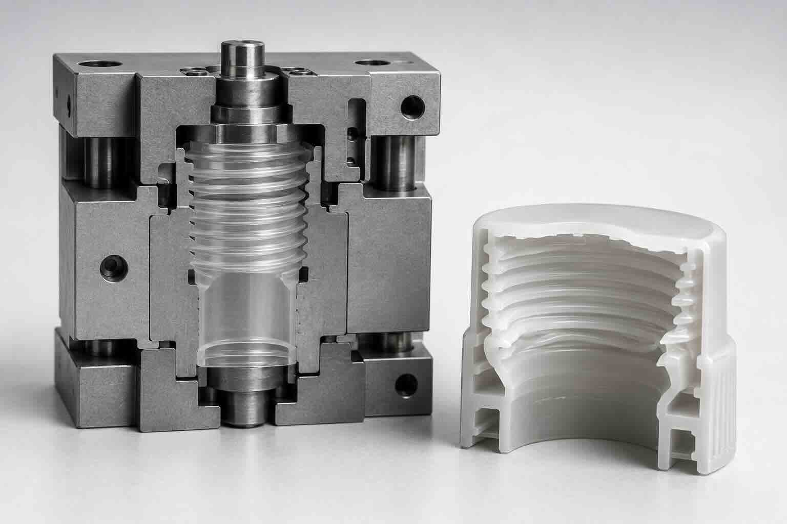
What Is Force Stripping?
Force stripping occurs when a molded thread is removed from a threaded core through elastic deformation of the plastic material.
Instead of rotating the thread off the core, the part expands temporarily during ejection.
Once the thread passes over the core profile, the material returns to its original shape.
This process relies entirely on the elasticity of the plastic material.
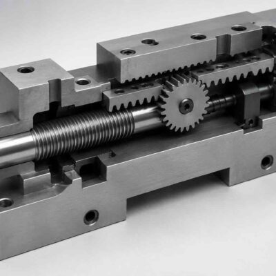
Mechanism 4 – Force Stripping Thread System
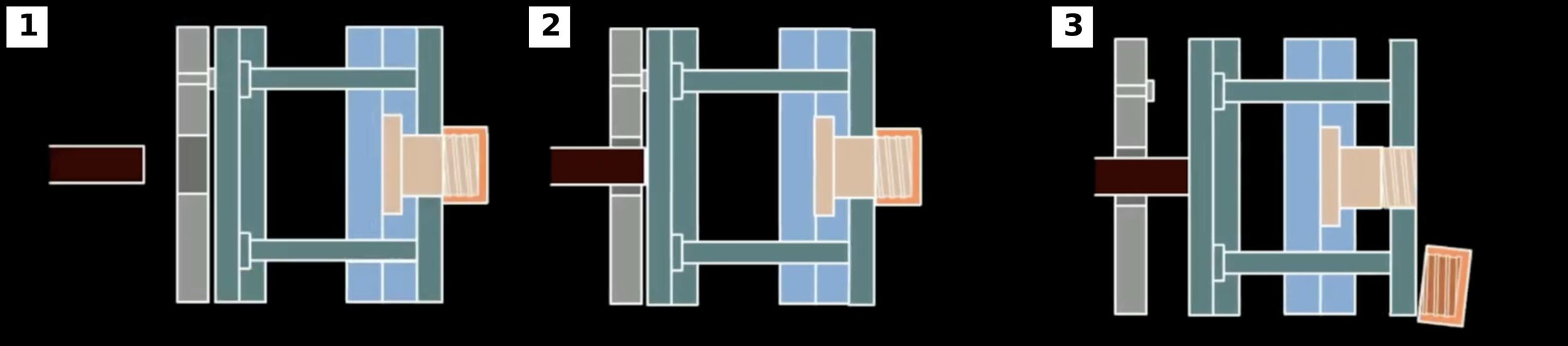
Mechanism 4 is the simplest of all ten thread release systems.
The mold contains:
- Threaded core
- Ejector system
- Stripper plate or ejector plate
No rotating components are required.
The thread is removed directly during ejection.
Operating Sequence
Step 1
Mold opens.
Step 2
Ejector system moves forward.
Step 3
The threaded section begins expanding.
Step 4
The thread deforms elastically.
Step 5
The thread passes over the core.
Step 6
The material recovers its shape.
Step 7
The part is fully ejected.
Why Force Stripping Works
Force stripping works because plastics are not perfectly rigid.
Most thermoplastics possess:
- Elasticity
- Flexibility
- Memory
When stressed within their elastic limits, they deform and then recover.
This behavior makes force stripping possible.
Metals generally cannot perform this function without permanent deformation.
Plastics can.
Elastic Deformation Versus Permanent Deformation
This distinction is critical.
Elastic Deformation
Material stretches.
Stress removed.
Material returns to original shape.
Desired condition.
Permanent Deformation
Material stretches.
Stress removed.
Material remains deformed.
Undesirable condition.
Successful force stripping always operates within the elastic range of the material.
The Three Conditions Required for Force Stripping
Force stripping requires three fundamental conditions.
Condition 1 – Suitable Material
The material must possess sufficient flexibility.
Condition 2 – Suitable Thread Geometry
The thread profile must allow deformation.
Condition 3 – Acceptable Strain Levels
The material strain must remain below the allowable limit.
If any one of these conditions is violated, force stripping becomes unreliable.
Material Selection
Material selection is the single most important factor.
Some plastics are excellent candidates.
Others should rarely be force stripped.
Excellent Materials
Polypropylene (PP)
Advantages
- High flexibility
- Good recovery
- Excellent fatigue resistance
Typical Applications
- Bottle caps
- Packaging closures
- Consumer products
One of the best force stripping materials available.
Low Density Polyethylene (LDPE)
Advantages
- Very flexible
- Excellent recovery
Suitable for:
- Flexible closures
- Consumer packaging
High Density Polyethylene (HDPE)
Advantages
- Good flexibility
- Good toughness
Suitable for many closure applications.
Moderate Materials
Thermoplastic Elastomers (TPE)
Advantages
- Excellent flexibility
Limitations
- Dimensional stability may be lower.
Nylon (PA)
Advantages
- High strength
Limitations
- Higher stiffness
- Higher stripping forces
May require careful design.
Difficult Materials
Polycarbonate (PC)
Higher stiffness.
Greater risk of stress cracking.
Acrylic (PMMA)
Very poor candidate.
High brittleness.
Glass Filled Materials
Generally poor candidates.
The glass fibers significantly reduce flexibility.
Understanding Material Recovery
Not all materials recover equally.
Consider two materials.
Material A
Elastic Recovery
98 Percent
Material B
Elastic Recovery
85 Percent
After repeated force stripping cycles:
Material A maintains thread geometry.
Material B may gradually deform.
Long-term dimensional stability must therefore be considered.
Thread Geometry Fundamentals
Even flexible materials can fail if the thread geometry is incorrect.
The most important parameters are:
- Thread depth
- Thread pitch
- Thread angle
- Engagement length
Thread Depth
Deep threads require greater expansion.
Greater expansion produces:
- Higher strain
- Higher ejection force
- Greater risk of damage
For force stripping, shallow threads are generally preferred.
Thread Pitch
Coarse threads generally perform better than fine threads.
Advantages:
- Lower stripping force
- Reduced friction
- Easier release
Fine threads are more challenging.
Thread Angle
Thread angle significantly influences stripping force.
Sharp V Threads
Higher stripping force.
Higher stress concentration.
Less desirable.
Rounded Threads
Lower stripping force.
Improved material flow.
Better recovery.
Preferred whenever possible.
Why Packaging Engineers Prefer Rounded Threads
Most beverage closures use thread profiles with:
- Generous radii
- Rounded roots
- Rounded crests
These features reduce:
- Stress concentration
- Thread damage
- Ejection force
while improving cycle consistency.
Thread Engagement Length
Long engagement lengths increase:
- Friction
- Contact area
- Required stripping force
Force stripping becomes increasingly difficult as engagement length increases.
Advantages of Force Stripping
When applicable, force stripping offers significant benefits.
Lower Tooling Cost
No:
- Motors
- Cylinders
- Gears
- Bearings
are required.
Shorter Cycle Time
No unscrewing motion is required.
The part is ejected directly.
Higher Reliability
Fewer moving components generally improve reliability.
Reduced Maintenance
Wear components are minimized.
Limitations of Force Stripping
Force stripping is not suitable for every application.
Limitation 1
Material restrictions.
Limitation 2
Thread geometry restrictions.
Limitation 3
Potential dimensional variation.
Limitation 4
Higher ejection forces.
Limitation 5
Potential stress whitening.
Typical Applications
Force stripping is commonly used for:
- Beverage closures
- Food packaging
- Cosmetic caps
- Household product caps
- Disposable products
These products are ideal because:
- Materials are flexible
- Threads are relatively shallow
- Production volumes are high
Comparing Force Stripping With Unscrewing Systems
| Parameter | Force Stripping | Unscrewing System |
|---|---|---|
| Tool Cost | Very Low | Medium to High |
| Cycle Time | Excellent | Moderate |
| Maintenance | Very Low | Medium |
| Reliability | Excellent | Good |
| Thread Complexity | Limited | Excellent |
| Material Flexibility Required | Yes | No |
The economic advantages explain why force stripping is widely used whenever technically feasible.
Design Parameters Required
Before evaluating a force stripping design, the engineer must know:
□ Material Type
□ Elastic Recovery
□ Thread Diameter
□ Thread Pitch
□ Thread Depth
□ Thread Angle
□ Engagement Length
□ Production Volume
These values will be used in the calculations presented in Part 2.
Force Stripping Design Checklist
Before considering force stripping verify:
□ Material suitable
□ Thread profile suitable
□ Thread depth acceptable
□ Engagement length acceptable
□ Production volume justifies analysis
□ Dimensional requirements reviewed
Part 2 – Strain Calculations, Ejection Forces and Material Limits
In Part 1, we introduced the principles of force stripping and examined the material and thread geometry requirements necessary for successful thread release.
The next step is determining whether a specific threaded component can be force stripped without damaging the part.
This requires engineering calculations.
Unlike mechanical or hydraulic unscrewing systems, force stripping depends on the ability of the plastic material to elastically deform during ejection.
The designer must evaluate:
- Thread expansion
- Circumferential strain
- Material stress
- Ejection force
- Friction effects
- Safety factors
These calculations determine whether force stripping is feasible.
Why Calculations Are Essential
Many force stripping designs appear successful during mold trials.
However, problems may emerge later:
- Stress whitening
- Thread deformation
- Cracking
- Loss of dimensional accuracy
- Long-term creep
A proper engineering evaluation reduces these risks.
Understanding Thread Expansion
During force stripping, the internal diameter of the threaded component must temporarily increase.
The amount of expansion depends on:
- Thread depth
- Core diameter
- Thread geometry
The larger the required expansion, the greater the material strain.
Basic Expansion Calculation
Assume:
Core Diameter = 38 mm
Thread Depth = 1.0 mm
The plastic thread must expand enough to pass over the thread crest.
Approximate Expansion Required
Expansion = 2 × Thread Depth
Calculation
Expansion = 2 × 1
Expansion = 2 mm
Result
Required Diameter Expansion = 2 mm
Why Thread Depth Is Critical
Thread depth has a major influence on force stripping success.
Consider:
Thread A
Depth = 0.5 mm
Expansion Required = 1 mm
Thread B
Depth = 1.5 mm
Expansion Required = 3 mm
Thread B requires three times more expansion.
This significantly increases:
- Material strain
- Ejection force
- Risk of failure
Circumferential Strain
Strain measures material deformation.
Formula
Strain = Diameter Change / Original Diameter
Example
Original Diameter = 38 mm
Expansion = 2 mm
Calculation
Strain = 2 / 38
Strain = 0.0526
Result
Strain = 5.3 Percent
This value becomes the basis for material evaluation.
Understanding Allowable Strain
Every material has a maximum allowable elastic strain.
Exceeding this limit causes permanent deformation.
Typical values:
Polypropylene (PP)
Allowable Strain
5 to 10 Percent
Excellent candidate.
High Density Polyethylene (HDPE)
Allowable Strain
4 to 8 Percent
Very good candidate.
Low Density Polyethylene (LDPE)
Allowable Strain
8 to 15 Percent
Excellent candidate.
Nylon (PA)
Allowable Strain
2 to 4 Percent
Requires careful evaluation.
Polycarbonate (PC)
Allowable Strain
2 to 3 Percent
Limited applications.
Acrylic (PMMA)
Allowable Strain
Less than 1 Percent
Generally unsuitable.
Example Material Evaluation
Thread Diameter
38 mm
Required Expansion
2 mm
Calculated Strain
5.3 Percent
Material
Polypropylene
Allowable Strain
10 Percent
Result
Acceptable
Safety Margin Exists
Stress in the Thread
Strain creates stress.
Formula
Stress = Elastic Modulus × Strain
Where
Stress = MPa
Elastic Modulus = MPa
Strain = Decimal
Example
Material
Polypropylene
Elastic Modulus
1500 MPa
Strain
0.053
Calculation
Stress = 1500 × 0.053
Stress = 79.5 MPa
Result
Thread Stress = 79.5 MPa
This value should be compared against the material’s allowable stress and yield characteristics.
Why Material Recovery Matters
Two materials may tolerate identical strain levels but recover differently.
Recovery determines:
- Thread accuracy
- Long-term dimensional stability
- Product quality
This is one reason why PP dominates closure applications.
Friction During Force Stripping
Expansion is not the only challenge.
The thread must also slide across the steel core.
This creates friction.
Friction increases:
- Ejection force
- Stress
- Wear
Factors Affecting Friction
Friction depends on:
- Surface finish
- Mold temperature
- Material type
- Lubricity
- Thread geometry
A polished core often dramatically improves force stripping performance.
Estimating Friction Force
Formula
Friction Force = Normal Force × Friction Coefficient
Example
Normal Force = 1000 N
Friction Coefficient = 0.25
Calculation
Friction Force = 1000 × 0.25
Friction Force = 250 N
Result
Additional Ejection Force = 250 N
Total Ejection Force
Total Ejection Force consists of:
Expansion Force
Friction Force
Vacuum Effects
Shrinkage Effects
Example
Expansion Force = 600 N
Friction Force = 250 N
Vacuum Force = 50 N
Shrinkage Force = 100 N
Calculation
Total Force
= 600 + 250 + 50 + 100
Total Force = 1000 N
Result
Required Ejection Force = 1000 N
Stripper Plate Loading
Force stripping typically uses:
- Stripper plates
- Ejector sleeves
- Ejector systems
The stripping system must withstand the calculated force.
Example
Required Force
1000 N
Safety Factor
2
Calculation
Design Force =
1000 × 2
Design Force = 2000 N
Result
The ejection system should be designed for:
2000 N
minimum.
Influence of Mold Temperature
Temperature significantly affects force stripping.
Higher temperatures generally produce:
- Lower stiffness
- Lower stripping force
- Improved flexibility
However:
Excessive temperature may create:
- Flash
- Deformation
- Longer cycle times
An optimized temperature window is required.
Influence of Cooling Time
Insufficient cooling increases:
- Deformation risk
Excessive cooling increases:
- Stripping force
A balance must be achieved.
Real Engineering Example
Product
Polypropylene Beverage Closure
Thread Diameter
38 mm
Thread Depth
1 mm
Expansion
2 mm
Step 1
Calculate Strain
Strain = 2 / 38
Strain = 5.3 Percent
Step 2
Evaluate Material
PP Allowable Strain
10 Percent
Result
Acceptable
Step 3
Calculate Stress
Stress =
1500 × 0.053
Stress = 79.5 MPa
Step 4
Estimate Friction Force
250 N
Step 5
Estimate Expansion Force
600 N
Step 6
Calculate Total Ejection Force
Total Force
= 600 + 250
Total Force
= 850 N
Step 7
Apply Safety Factor
Safety Factor = 2
Design Force
= 850 × 2
Design Force
= 1700 N
Result
Recommended Ejection Capacity
1700 N Minimum
Common Design Mistakes
Mistake 1
Ignoring strain calculations.
Mistake 2
Assuming all plastics behave similarly.
Mistake 3
Ignoring friction effects.
Mistake 4
Using sharp thread profiles.
Mistake 5
Ignoring temperature effects.
Design Checklist
Before approving a force stripping design verify:
□ Thread expansion calculated
□ Strain calculated
□ Material strain limits verified
□ Stress calculated
□ Friction considered
□ Ejection force estimated
□ Safety factor applied
□ Thread profile reviewed
□ Mold temperature evaluated
□ Cooling strategy reviewed
Part 3 – Thread Profile Optimization, Stress Concentration and Long-Term Performance
In Part 2, we examined the engineering calculations used to evaluate force stripping feasibility.
We calculated:
- Thread expansion
- Circumferential strain
- Material stress
- Friction forces
- Ejection forces
- Safety factors
These calculations determine whether force stripping is theoretically possible.
However, long-term success depends heavily on thread design.
Two parts made from the same material may behave completely differently depending on:
- Thread profile
- Root radius
- Thread angle
- Draft angle
- Surface finish
This chapter focuses on the geometry that separates successful force stripping designs from expensive failures.
Why Thread Geometry Matters
Many force stripping failures are not caused by the material.
They are caused by poor thread design.
A properly designed thread:
- Reduces stress
- Lowers stripping force
- Improves recovery
- Extends mold life
A poorly designed thread can create:
- Stress whitening
- Cracking
- Permanent deformation
- Excessive ejection force
even when a suitable material is used.
Understanding Stress Concentration
Stress does not distribute evenly throughout a threaded part.
Certain locations experience much higher stress.
These locations are called stress concentrations.
The most critical locations are:
- Thread roots
- Sharp corners
- Thread transitions
Why Sharp Corners Are Dangerous
A sharp corner concentrates stress into a very small area.
This dramatically increases the likelihood of:
- Cracking
- Whitening
- Fatigue failure
Example
Two thread designs:
Thread A
Sharp Root Radius
0.05 mm
Thread B
Rounded Root Radius
0.50 mm
Thread B typically experiences much lower peak stress.
This is one reason why rounded thread profiles are preferred.
Thread Root Radius
The thread root is the most highly stressed region during force stripping.
Increasing root radius provides:
- Lower stress concentration
- Better material flow
- Improved fatigue resistance
Design Guideline
Whenever possible:
Root Radius ≥ 10 Percent of Thread Depth
Example
Thread Depth = 1.2 mm
Calculation
Minimum Radius =
1.2 × 0.10
Minimum Radius = 0.12 mm
Engineering Practice
Use:
0.25 to 0.50 mm
whenever product requirements allow.
Thread Crest Radius
The crest also influences stripping behavior.
Sharp crests tend to:
- Increase friction
- Increase stress
- Damage mating threads
Rounded crests generally improve performance.
Thread Angle
Thread angle has a significant influence on stripping force.
Sharp V Threads
[INSERT MECHANISM 4 IMAGE HERE]
Characteristics
- High stress concentration
- High friction
- Difficult force stripping
Common Included Angle
60 Degrees
Modified Rounded Threads
Characteristics
- Lower stress concentration
- Lower stripping force
- Better recovery
Preferred for force stripping applications.
Buttress Threads
Buttress threads are commonly used in closure systems.
Advantages
- High load capacity
- Easier stripping
- Improved release direction
Many packaging applications successfully use modified buttress profiles.
Thread Depth Optimization
Deep threads are often unnecessary.
Many designers specify excessive thread depth.
Consequences include:
- Higher strain
- Higher friction
- Higher ejection force
Example
Thread A
Depth = 0.8 mm
Thread B
Depth = 1.6 mm
Thread B requires approximately twice the expansion.
This greatly increases stripping difficulty.
Draft Angle Considerations
Draft is often overlooked in threaded components.
Small draft angles can improve release.
Benefits include:
- Reduced friction
- Lower ejection force
- Improved recovery
However:
Excessive draft may affect thread functionality.
Balance is required.
Surface Finish Effects
Surface finish has a major influence on force stripping.
Rough Surface
Produces:
- Higher friction
- Higher wear
- Higher stripping force
Polished Surface
Produces:
- Lower friction
- Improved release
- Better consistency
For force stripping applications, polished cores are strongly recommended.
Mold Temperature Effects
Thread geometry alone does not determine performance.
Temperature influences material behavior.
Higher mold temperatures generally produce:
- Better material flow
- Lower residual stress
However:
Excessive temperatures may increase cycle time.
Residual Stress
Residual stress is stress trapped inside the molded part.
Sources include:
- Uneven cooling
- Poor gate location
- Excessive packing pressure
Residual stress reduces force stripping performance.
A part with high residual stress may fail even when strain calculations appear acceptable.
Stress Whitening
One of the most common force stripping defects is stress whitening.
Symptoms:
- White marks near threads
- Reduced cosmetic quality
- Localized material damage
Causes:
- Excessive strain
- Sharp corners
- Poor material selection
Creep Behavior
Force stripping calculations often focus on immediate deformation.
However, long-term deformation must also be considered.
This phenomenon is called creep.
Creep occurs when:
- Stress remains present
- Material slowly deforms over time
Why Creep Matters
A closure may pass inspection immediately after molding.
Weeks later:
- Thread dimensions change
- Seal performance changes
- Product quality decreases
Designers must evaluate long-term stability.
Material Fatigue
Force stripping subjects the material to repeated deformation.
Most consumer products experience only one stripping cycle.
However:
Certain reusable products may experience repeated loading.
Material fatigue becomes important when:
- Threads are repeatedly assembled
- Threads are repeatedly removed
Comparing Materials
Polypropylene (PP)
Excellent fatigue resistance.
Excellent recovery.
Industry standard for force stripping.
HDPE
Good fatigue resistance.
Good recovery.
Widely used.
Nylon
Higher strength.
Lower flexibility.
Requires careful design.
Polycarbonate
Moderate strength.
Limited flexibility.
Stress cracking may occur.
Acrylic
Poor fatigue resistance.
Poor candidate.
Finite Life Design
Many engineers assume force stripping either works or fails.
In reality, there are three possible outcomes.
Infinite Life
Material remains below critical stress.
Excellent long-term performance.
Finite Life
Part survives initially.
Gradual degradation occurs.
Immediate Failure
Material exceeds allowable limits.
Part fails during ejection.
The objective is always to design within the infinite life region whenever possible.
Engineering Example
Polypropylene Beverage Closure
Thread Diameter
38 mm
Thread Depth
1.0 mm
Root Radius
0.05 mm
Observation
Stress whitening occurs.
Design Modification
Increase Radius
0.50 mm
Result
- Lower stress concentration
- Lower stripping force
- Improved appearance
- Better recovery
This demonstrates how small geometry changes can dramatically improve performance.
Advanced Design Guidelines
For high-volume force stripping applications:
Use:
- Rounded thread roots
- Rounded thread crests
- Moderate thread depth
- Polished core surfaces
- Optimized mold temperatures
Avoid:
- Sharp V threads
- Deep thread profiles
- Brittle materials
- Excessive residual stress
Common Design Mistakes
Mistake 1
Using standard metal thread profiles.
Mistake 2
Ignoring root radii.
Mistake 3
Using excessive thread depth.
Mistake 4
Ignoring residual stress.
Mistake 5
Failing to evaluate long-term creep.
Design Checklist
Before approving a force stripping design verify:
□ Thread depth optimized
□ Root radius optimized
□ Crest radius optimized
□ Thread angle reviewed
□ Surface finish specified
□ Residual stress minimized
□ Material fatigue considered
□ Creep behavior evaluated
□ Mold temperature optimized
□ Long-term dimensional stability reviewed
Part 4 – Complete Design Example, Cost Analysis, Reliability and Best Practices
In Parts 1, 2 and 3, we developed the engineering foundation required to design force stripping thread systems.
We examined:
- Material selection
- Elastic deformation
- Thread expansion
- Circumferential strain
- Ejection forces
- Friction effects
- Thread profile optimization
- Stress concentration
- Creep
- Fatigue
- Long-term stability
The final step is integrating these concepts into a complete engineering workflow.
This chapter demonstrates how experienced mold designers evaluate force stripping applications, optimize thread geometry and determine whether force stripping is preferable to a conventional unscrewing mechanism.
Complete Design Example
We will evaluate a polypropylene closure for force stripping.
Product Data
Part Description
Beverage Closure
Material
Polypropylene (PP)
Thread Diameter
38 mm
Thread Pitch
3 mm
Thread Depth
1.0 mm
Thread Engagement Length
9 mm
Annual Production
120 Million Parts
Target Mold Life
15 Years
Step 1 – Evaluate Material Suitability
Material
Polypropylene
Advantages
- Excellent flexibility
- Excellent elastic recovery
- Excellent fatigue resistance
Result
Suitable for force stripping.
Step 2 – Calculate Required Expansion
Approximate Formula
Expansion =
2 × Thread Depth
Calculation
Expansion =
2 × 1
Expansion = 2 mm
Result
Required Diameter Expansion = 2 mm
Step 3 – Calculate Strain
Formula
Strain =
Diameter Change
/
Original Diameter
Calculation
Strain =
2 / 38
Strain = 0.0526
Result
Strain = 5.3 Percent
Step 4 – Compare With Material Limits
Polypropylene Allowable Strain
Approximately 10 Percent
Calculated Strain
5.3 Percent
Result
Acceptable
Safety Margin Exists
Step 5 – Estimate Thread Stress
Formula
Stress =
Elastic Modulus × Strain
Polypropylene Elastic Modulus
1500 MPa
Calculation
Stress =
1500 × 0.053
Stress = 79.5 MPa
Result
Acceptable for short-term elastic deformation.
Step 6 – Estimate Ejection Force
Expansion Force
600 N
Friction Force
250 N
Vacuum Force
50 N
Total Force
600 + 250 + 50
Total Force = 900 N
Apply Safety Factor
2
Design Force
1800 N
Result
Recommended Ejection Capacity
1800 N Minimum
Step 7 – Evaluate Thread Geometry
Thread Profile
Modified Rounded Thread
[INSERT MECHANISM 4 IMAGE HERE]
Advantages
- Lower friction
- Reduced stress concentration
- Better recovery
Result
Recommended
Step 8 – Evaluate Root Radius
Thread Depth
1 mm
Recommended Root Radius
0.25 to 0.50 mm
Selected Radius
0.40 mm
Result
Good stress distribution.
Step 9 – Evaluate Production Volume
Annual Production
120 Million Parts
Expected Production Life
15 Years
Total Production
1.8 Billion Parts
This production volume strongly favors:
- Simple molds
- Reliable molds
- Low-maintenance molds
Force stripping becomes highly attractive.
Why Force Stripping Dominates Packaging
Most beverage closures worldwide use force stripping.
Reasons include:
- Extremely high production volume
- Low tooling cost
- Fast cycle time
- Excellent reliability
Even a one-second cycle improvement can save enormous production costs over billions of parts.
Cost Comparison
Consider a 64-cavity beverage closure mold.
Force Stripping System
Components
- Threaded core
- Stripper system
Approximate Relative Cost
100 Percent
Baseline
Mechanical Unscrewing System
Components
- Gears
- Bearings
- Drive components
- Maintenance items
Relative Cost
150 to 250 Percent
Hydraulic Unscrewing System
Components
- Cylinders
- Hydraulic circuits
- Additional machining
Relative Cost
200 to 300 Percent
Force stripping often provides the lowest tooling investment.
Cycle Time Comparison
Force Stripping
Thread released directly.
No rotation required.
Cycle Time
Shortest
Mechanical Unscrewing
Requires rotational movement.
Cycle Time
Longer
Hydraulic Unscrewing
Requires hydraulic actuation.
Cycle Time
Often longest
For high-volume products, cycle time becomes a major economic factor.
Reliability Comparison
One of the greatest advantages of force stripping is simplicity.
Force Stripping
Moving Components
Very Few
Reliability
Excellent
Mechanical Unscrewing
Moving Components
Moderate
Reliability
Very Good
Hydraulic Unscrewing
Moving Components
Highest
Reliability
Good to Excellent
The reduction in moving components dramatically improves long-term reliability.
Maintenance Comparison
Force Stripping
Maintenance Requirements
Minimal
Typical Maintenance
- Cleaning
- Core polishing
Mechanical Systems
Maintenance Requirements
Moderate
Typical Maintenance
- Gear inspection
- Bearing replacement
Hydraulic Systems
Maintenance Requirements
Higher
Typical Maintenance
- Seal replacement
- Cylinder inspection
- Hydraulic servicing
Life-Cycle Cost Analysis
Experienced mold designers rarely evaluate only mold cost.
Instead they calculate:
Total Cost of Ownership
Formula
Total Cost =
Tool Cost
Maintenance Cost
Downtime Cost
Replacement Cost
Example
Force Stripping Mold
Tool Cost
€100,000
Maintenance
€20,000
Downtime
€10,000
Total
€130,000
Mechanical Unscrewing Mold
Tool Cost
€160,000
Maintenance
€60,000
Downtime
€40,000
Total
€260,000
Result
Force Stripping Saves
€130,000
Over Mold Life
This explains why force stripping is often preferred whenever technically feasible.
When Force Stripping Should NOT Be Used
Force stripping is not a universal solution.
Situation 1
Deep Threads
High expansion requirements.
Situation 2
Fine Threads
High friction.
Situation 3
Brittle Materials
Risk of cracking.
Situation 4
Glass Filled Materials
Poor elastic recovery.
Situation 5
Precision Thread Applications
Dimensional requirements may exceed force stripping capability.
In these situations, unscrewing mechanisms are often preferable.
Decision Matrix
| Design Requirement | Force Stripping | Unscrewing |
|---|---|---|
| Lowest Cost | Excellent | Moderate |
| Fastest Cycle | Excellent | Moderate |
| Deep Threads | Poor | Excellent |
| Fine Threads | Poor | Excellent |
| Flexible Materials | Excellent | Good |
| Brittle Materials | Poor | Excellent |
| Maintenance | Excellent | Moderate |
| Reliability | Excellent | Very Good |
Best Engineering Practices
Best Practice 1
Evaluate force stripping first.
Never assume an unscrewing system is required.
Best Practice 2
Use flexible materials whenever possible.
Best Practice 3
Use rounded thread profiles.
Best Practice 4
Minimize thread depth.
Best Practice 5
Maximize root radius.
Best Practice 6
Polish threaded cores.
Best Practice 7
Control mold temperature.
Best Practice 8
Reduce residual stress.
Best Practice 9
Validate performance with production trials.
Best Practice 10
Consider total ownership cost rather than tooling cost alone.
Force Stripping Design Workflow
Step 1
Evaluate material.
Step 2
Evaluate thread geometry.
Step 3
Calculate expansion.
Step 4
Calculate strain.
Step 5
Verify allowable strain.
Step 6
Estimate ejection force.
Step 7
Optimize thread profile.
Step 8
Evaluate production volume.
Step 9
Compare against unscrewing systems.
Step 10
Finalize design.
Final Design Checklist
Before approving a force stripping design verify:
□ Material suitable
□ Expansion calculated
□ Strain verified
□ Stress reviewed
□ Friction considered
□ Ejection force calculated
□ Root radius optimized
□ Thread profile optimized
□ Surface finish specified
□ Production volume evaluated
□ Life-cycle cost reviewed
□ Reliability target achieved
Conclusion
Force stripping is one of the most powerful cost-reduction tools available to injection mold designers.
When properly applied, it offers:
- Lower tooling costs
- Faster cycle times
- Higher reliability
- Reduced maintenance
However, successful force stripping requires careful evaluation of:
- Material behavior
- Thread geometry
- Strain levels
- Stress concentration
- Long-term dimensional stability
By applying the engineering principles presented throughout this guide, designers can confidently determine whether a threaded plastic component can be force stripped or whether a more complex unscrewing mechanism is required.