Fundamentals, Operating Principles and Mechanism Overview
Hydraulic unscrewing systems are among the most powerful and versatile mechanisms used in injection molds. When thread geometry, product size, shrinkage forces, or production requirements exceed the capabilities of conventional mechanical systems, hydraulic actuation often becomes the preferred solution.
Unlike motor-driven or rack-and-pinion mechanisms, hydraulic systems generate motion through pressurized oil. This allows very large forces to be produced in a compact space, making hydraulic systems particularly suitable for large threaded components, deep threads, and demanding engineering materials.
In this article we focus on:
- Mechanism 3 – Hydraulic Continuous Internal Thread Unscrewing
- Mechanism 7 – Hydraulic Cylinder Driven Unscrewing
These two mechanisms represent the most common hydraulic thread release solutions used in modern injection molds.
Why Use Hydraulic Unscrewing Systems?
Many threaded components can be released using mechanical systems.
However, some applications present challenges such as:
- Large thread diameters
- Deep thread engagement
- High shrinkage materials
- Limited mold space
- High release torque
In these situations, hydraulic systems offer significant advantages.
Hydraulic pressure can generate extremely high forces while maintaining compact actuator dimensions.
This makes hydraulic unscrewing systems attractive for demanding industrial applications.
What Is a Hydraulic Unscrewing System?
A hydraulic unscrewing system converts hydraulic energy into rotational or linear motion.
The system typically consists of:
- Hydraulic cylinder
- Hydraulic power source
- Rack and pinion mechanism
- Threaded core
- Bearings
- Guide components
The hydraulic cylinder generates force.
That force is then converted into rotational movement capable of releasing the threaded component.
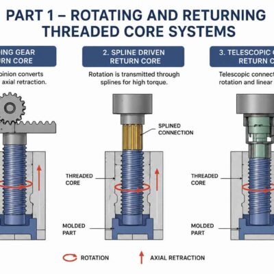
Mechanism 3 – Hydraulic Continuous Internal Thread Unscrewing
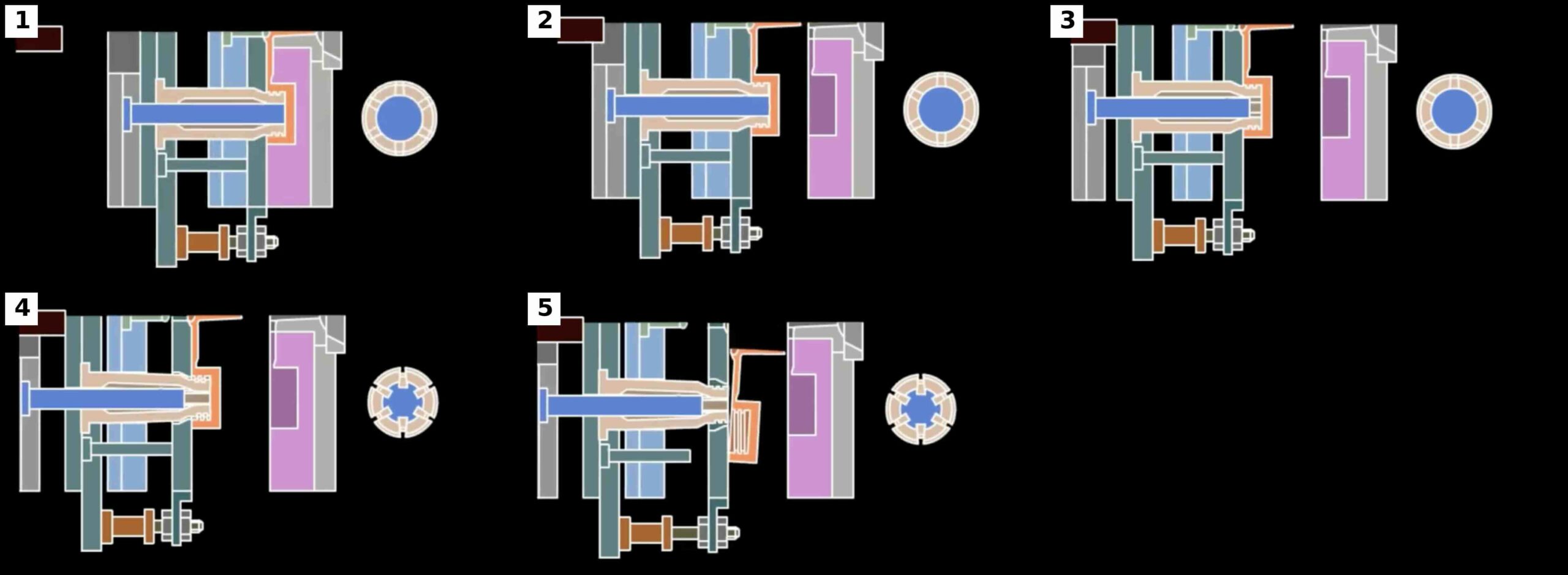
Mechanism 3 is commonly used for internal threaded components.
The mechanism operates by combining:
- Hydraulic motion
- Collapsible thread release
- Controlled ejection
This design is particularly useful when the threaded core must be released from inside the molded component.
Operating Sequence
Step 1
Mold opens.
Step 2
The ejector system begins moving.
Step 3
The support mandrel retracts.
Step 4
The threaded core contracts.
Step 5
The thread disengages.
Step 6
A secondary ejection system pushes the part out of the mold.
Step 7
During mold closing, the support mandrel expands the core again.
Advantages
- Suitable for internal threads
- High force capability
- Excellent process control
- Fully automatic operation
Limitations
- More complex design
- Higher mold cost
- Additional hydraulic requirements
Typical Applications
- Pipe fittings
- Fluid connectors
- Engineering housings
- Large threaded components
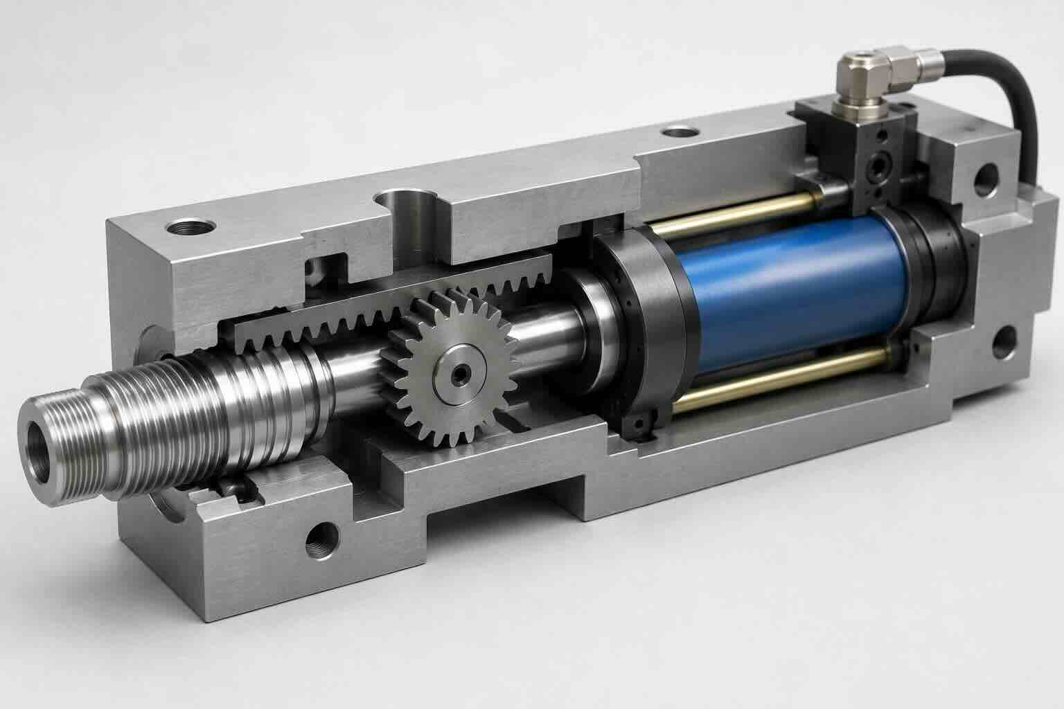
Mechanism 7 – Hydraulic Cylinder Driven Unscrewing
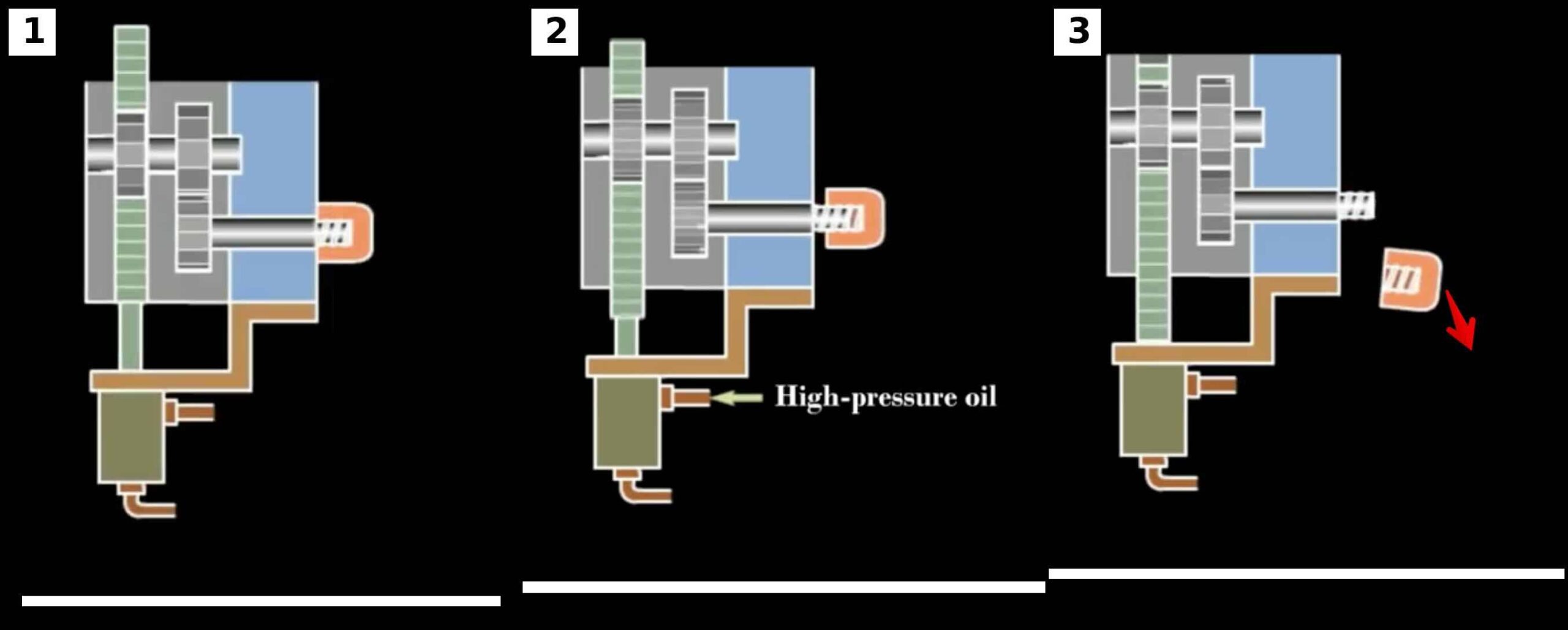
Mechanism 7 uses a hydraulic cylinder to drive a rack and pinion system.
The cylinder produces linear movement.
The rack converts this movement into rotation.
The threaded core rotates and releases the molded component.
This approach combines:
- High force capability
- Reliable operation
- Compact packaging
Operating Sequence
Step 1
Mold opens.
Step 2
Hydraulic cylinder extends.
Step 3
Rack moves linearly.
Step 4
Pinion rotates.
Step 5
Threaded core rotates.
Step 6
Part disengages.
Step 7
Part is ejected.
Advantages
- High torque capability
- Excellent control
- Suitable for large threads
- Reliable operation
Limitations
- Hydraulic plumbing required
- Seal maintenance required
- Increased mold complexity
Typical Applications
- Industrial closures
- Pipe systems
- Automotive reservoirs
- Heavy-duty molded components
Why Hydraulic Systems Produce High Force
Hydraulic systems operate according to one of the most important engineering principles:
Pressure applied to a confined fluid creates force.
This allows relatively small cylinders to generate extremely large loads.
Unlike mechanical systems, force is generated directly through fluid pressure.
Fundamental Hydraulic Relationship
The most important hydraulic formula is:
Force = Pressure × Area
Where:
Force = N
Pressure = MPa
Area = mm²
This equation forms the basis of all hydraulic sizing calculations.
Example
Cylinder Pressure
12 MPa
Cylinder Diameter
40 mm
Step 1
Calculate Piston Area
Area = 3.1416 × Diameter² / 4
Area = 3.1416 × 40² / 4
Area = 1256 mm²
Step 2
Calculate Force
Force = 12 × 1256
Force = 15,072 N
Result
Cylinder Force = 15.1 kN
This demonstrates why hydraulic systems are capable of generating very high loads.
Comparing Hydraulic and Mechanical Systems
| Parameter | Hydraulic | Mechanical |
|---|---|---|
| Force Capability | Excellent | Good |
| Torque Capability | Excellent | Good |
| Mold Cost | High | Medium |
| Maintenance | Medium | Low |
| Flexibility | Excellent | Good |
| Space Efficiency | Excellent | Good |
Hydraulic systems are generally selected when force requirements become difficult to achieve using purely mechanical solutions.
Thread Applications Best Suited for Hydraulics
Hydraulic systems are particularly effective when:
- Thread diameter exceeds 50 mm
- Thread engagement is long
- Material shrinkage is significant
- Release torque is high
- Production volumes justify higher tooling costs
Internal Threads Versus External Threads
Hydraulic systems are frequently selected for internal threads.
Reasons include:
- Difficult release conditions
- Limited access
- High retention forces
External threads can often be handled using mechanical systems.
Internal threads frequently require hydraulic assistance.
Common Hydraulic Components
A hydraulic unscrewing system may contain:
Hydraulic Cylinder
Generates force.
Rack
Converts linear movement.
Pinion
Produces rotation.
Bearings
Support rotating components.
Hydraulic Seals
Prevent oil leakage.
Guide Components
Maintain alignment.
Advantages of Hydraulic Systems in High-Volume Production
A properly designed hydraulic system offers:
- Consistent performance
- Excellent repeatability
- Long service life
- High force capacity
Many hydraulic molds operate successfully for millions of production cycles.
Common Design Challenges
Hydraulic systems also introduce new engineering challenges.
Challenge 1
Oil leakage
Challenge 2
Seal wear
Challenge 3
Pressure losses
Challenge 4
Heat generation
Challenge 5
Maintenance access
These topics will be addressed in later sections.
Selecting Between Mechanism 3 and Mechanism 7
The choice depends on application requirements.
Choose Mechanism 3 when:
- Internal threads are difficult to release
- Collapsible cores are required
- Complex internal geometry exists
Choose Mechanism 7 when:
- High torque is required
- Rack and pinion systems are suitable
- Simplicity is preferred
Design Parameters Required
Before sizing a hydraulic unscrewing system, the following values must be known:
□ Thread Diameter
□ Thread Pitch
□ Engagement Length
□ Number of Turns
□ Required Torque
□ Desired Cycle Time
□ Available Hydraulic Pressure
□ Available Mold Space
These values will drive all subsequent calculations.
Hydraulic Unscrewing Design Checklist
Before selecting a hydraulic system verify:
□ Thread geometry reviewed
□ Required turns calculated
□ Required torque estimated
□ Internal thread requirements reviewed
□ Mold space evaluated
□ Hydraulic pressure available
□ Maintenance access considered
□ Reliability target established
Part 2 – Cylinder Sizing, Force Calculations and Torque Generation
In Part 1, we examined the operating principles of hydraulic unscrewing systems and introduced:
- Mechanism 3 – Hydraulic Continuous Internal Thread Unscrewing
- Mechanism 7 – Hydraulic Cylinder Driven Unscrewing
The next step is determining the size of the hydraulic components required to release the molded thread.
Hydraulic systems are unique because they generate force directly through fluid pressure.
Unlike mechanical systems, where force is generated through gears and shafts, hydraulic systems begin with pressure and convert it into motion.
This chapter explains how to calculate:
- Cylinder force
- Piston area
- Hydraulic pressure
- Rack force
- Torque generation
- Hydraulic efficiency
- Safety factors
These calculations form the foundation of hydraulic unscrewing design.
The Fundamental Hydraulic Formula
Every hydraulic calculation begins with the same equation.
Formula
Force = Pressure × Area
Where
Force = N
Pressure = MPa
Area = mm²
This relationship determines the force available from a hydraulic cylinder.
Understanding Hydraulic Pressure
Pressure is the energy source of a hydraulic system.
Typical mold hydraulic pressures:
Low Pressure
5 MPa
Medium Pressure
10 MPa
High Pressure
16 MPa
Heavy-Duty Systems
21 MPa
Higher pressure generates more force but increases:
- Seal loading
- Component stress
- Heat generation
Calculating Piston Area
Formula
Area = 3.1416 × Diameter² / 4
Example
Cylinder Diameter
40 mm
Calculation
Area =
3.1416 × 40²
/
4
Area = 1256 mm²
Result
Piston Area = 1256 mm²
Calculating Cylinder Force
Formula
Force = Pressure × Area
Example
Pressure = 12 MPa
Area = 1256 mm²
Calculation
Force = 12 × 1256
Force = 15,072 N
Result
Cylinder Force = 15.1 kN
This force becomes available to drive the unscrewing mechanism.
Why Cylinder Diameter Matters
Force increases with the square of cylinder diameter.
This means small diameter changes can produce large force increases.
Example
Cylinder Diameter
40 mm
Area = 1256 mm²
Cylinder Diameter
50 mm
Area = 1963 mm²
Force Increase
1963 / 1256
Force Increase = 1.56
Result
A 25 percent increase in diameter produces approximately 56 percent more force.
This principle is extremely important when sizing cylinders.
Hydraulic Force Required for Thread Release
Before selecting a cylinder, the required thread release torque must be known.
Assume:
Required Torque = 80 Nm
The hydraulic system must generate enough force to create this torque.
Rack and Pinion Torque Conversion
Mechanism 7 uses:
Hydraulic Cylinder
↓
Rack
↓
Pinion
↓
Threaded Core
The cylinder force becomes rack force.
The rack force becomes pinion torque.
Calculating Pinion Torque
Formula
Torque = Force × Radius
Where
Radius = Pitch Diameter / 2
Example
Pinion Diameter = 60 mm
Radius = 30 mm
Convert Radius
30 mm = 0.03 m
Cylinder Force = 15,072 N
Calculation
Torque = 15,072 × 0.03
Torque = 452 Nm
Result
Available Torque = 452 Nm
This demonstrates why hydraulic systems are capable of producing extremely high torque.
Working Backwards From Torque
Design often begins with required torque.
The engineer then calculates the cylinder size required.
Example
Required Torque = 150 Nm
Pinion Diameter = 60 mm
Radius = 0.03 m
Formula
Force = Torque / Radius
Calculation
Force = 150 / 0.03
Force = 5000 N
Result
Required Rack Force = 5000 N
Determining Cylinder Area
Formula
Area = Force / Pressure
Example
Required Force = 5000 N
Available Pressure = 10 MPa
Calculation
Area = 5000 / 10
Area = 500 mm²
Determining Cylinder Diameter
Formula
Diameter = Square Root Of
(4 × Area)
/
3.1416
Example
Area = 500 mm²
Calculation
Diameter = 25.2 mm
Engineering Practice
Select Next Standard Size
Chosen Diameter = 32 mm
Result
Required Cylinder Diameter = 32 mm
Cylinder Stroke Calculation
The cylinder stroke determines how far the rack can travel.
Formula
Stroke = Required Rack Travel
Example
Thread Engagement = 12 mm
Pitch = 3 mm
Turns = 4
Pinion Diameter = 60 mm
Circumference =
3.1416 × 60
Circumference = 188.5 mm
Rack Travel =
188.5 × 4
Rack Travel = 754 mm
Result
Required Cylinder Stroke = 754 mm
This calculation immediately shows one potential problem.
The cylinder becomes very large.
Design Optimization
When cylinder stroke becomes excessive, possible solutions include:
- Increase thread pitch
- Reduce thread engagement
- Increase pinion ratio
- Use multiple gear stages
- Switch to motor-driven systems
These decisions significantly affect mold cost and complexity.
Hydraulic Efficiency
Not all hydraulic energy reaches the threaded core.
Losses occur due to:
- Seal friction
- Pressure losses
- Mechanical friction
- Rack friction
- Bearing drag
Typical hydraulic efficiency:
85 to 95 percent
Example
Calculated Force = 15,072 N
Efficiency = 90 percent
Calculation
Available Force =
15,072 × 0.90
Available Force = 13,565 N
Result
Usable Force = 13.6 kN
Always account for efficiency losses.
Applying Safety Factors
Hydraulic systems experience:
- Pressure fluctuations
- Seal wear
- Temperature changes
- Friction variation
Safety factors must be included.
Recommended Values
Standard Mold
Safety Factor = 2
Automotive Mold
Safety Factor = 2.5
Medical Mold
Safety Factor = 3
Example
Required Torque = 150 Nm
Safety Factor = 2.5
Calculation
Design Torque =
150 × 2.5
Design Torque = 375 Nm
The hydraulic system must be capable of producing:
375 Nm
minimum.
Complete Hydraulic Sizing Example
Product
Industrial Threaded Fitting
Thread Diameter
50 mm
Pitch
5 mm
Engagement
20 mm
Required Torque
150 Nm
Available Pressure
10 MPa
Step 1
Calculate Required Force
Force = 150 / 0.03
Force = 5000 N
Step 2
Apply Safety Factor
Force =
5000 × 2.5
Force = 12,500 N
Step 3
Calculate Required Area
Area =
12,500 / 10
Area = 1250 mm²
Step 4
Calculate Cylinder Diameter
Diameter ≈ 40 mm
Step 5
Select Standard Cylinder
Chosen Diameter
50 mm
Result
Recommended Cylinder Diameter = 50 mm
Recommended Pressure = 10 MPa
Design Force = 19.6 kN
This provides a substantial design margin.
Common Hydraulic Design Mistakes
Mistake 1
Ignoring efficiency losses.
Mistake 2
Using theoretical pressure instead of actual pressure.
Mistake 3
Selecting insufficient cylinder stroke.
Mistake 4
Ignoring safety factors.
Mistake 5
Underestimating thread release torque.
Design Checklist
Before selecting a hydraulic cylinder verify:
□ Required turns calculated
□ Required torque calculated
□ Rack force calculated
□ Pressure verified
□ Piston area calculated
□ Cylinder diameter selected
□ Cylinder stroke verified
□ Efficiency considered
□ Safety factor applied
□ Maintenance access reviewed
Part 3 – Rod Sizing, Hydraulic Power, Oil Flow, Seals and Reliability
In Part 2 we sized the hydraulic cylinder and calculated:
- Hydraulic force
- Piston area
- Pressure requirements
- Rack force
- Torque generation
- Safety factors
A cylinder that produces sufficient force is only the beginning of a successful hydraulic design.
The engineer must also ensure that:
- The piston rod does not buckle
- The hydraulic system can supply enough oil
- The pump provides sufficient flow
- The seals survive millions of cycles
- The system remains reliable over the expected mold life
This chapter focuses on the supporting calculations required to transform a theoretical hydraulic cylinder into a production-ready hydraulic unscrewing system.
Why Rod Design Is Important
Many engineers focus exclusively on cylinder force.
However, hydraulic cylinders fail more frequently because of:
- Rod buckling
- Rod bending
- Seal wear
- Side loading
rather than insufficient force.
A properly sized rod is therefore critical.
Understanding Cylinder Rod Loads
The piston rod experiences:
- Compression
- Tension
- Bending
- Fatigue loading
The most dangerous condition is compression.
Compression can cause rod buckling.
What Is Buckling?
Buckling occurs when a slender rod suddenly bends under compression.
Even though the material has not reached its yield strength, the rod may collapse.
This is one of the most common failure mechanisms in long-stroke hydraulic cylinders.
Buckling Risk Factors
Buckling risk increases when:
- Stroke length increases
- Rod diameter decreases
- Applied force increases
Hydraulic unscrewing systems with long rack travel are particularly susceptible.
Rod Slenderness Ratio
A useful design indicator is the ratio:
Slenderness Ratio = Rod Length / Rod Diameter
General Guidelines
Less Than 20
Very Safe
20 to 40
Usually Acceptable
40 to 60
Requires Detailed Analysis
Greater Than 60
High Buckling Risk
Example
Rod Length = 300 mm
Rod Diameter = 20 mm
Calculation
Slenderness Ratio = 300 / 20
Slenderness Ratio = 15
Result
Buckling Risk = Low
Practical Rod Sizing Rule
For hydraulic unscrewing systems:
Recommended Rod Diameter
30 to 50 percent of cylinder diameter
Example
Cylinder Diameter = 50 mm
Recommended Rod
15 to 25 mm
Engineering Practice
Choose:
25 mm Rod
This improves rigidity and seal life.
Oil Volume Calculation
The hydraulic system must provide sufficient oil to move the cylinder.
Formula
Volume = Area × Stroke
Example
Cylinder Diameter = 50 mm
Stroke = 400 mm
Step 1
Calculate Area
Area =
3.1416 × 50²
/
4
Area = 1963 mm²
Step 2
Calculate Volume
Volume = 1963 × 400
Volume = 785,200 mm³
Convert
Volume = 0.785 Liters
Result
Oil Required = 0.785 Liters
Why Oil Volume Matters
Oil volume determines:
- Pump sizing
- Hydraulic response time
- Reservoir capacity
Insufficient oil supply causes:
- Slow operation
- Pressure drops
- Inconsistent performance
Flow Rate Calculation
Flow rate determines cylinder speed.
Formula
Flow Rate = Volume / Time
Example
Volume = 0.785 Liters
Desired Stroke Time = 1.5 Seconds
Calculation
Flow Rate =
0.785 / 1.5
Flow Rate = 0.523 L/s
Convert
Flow Rate = 31.4 L/min
Result
Required Flow Rate = 31.4 L/min
Hydraulic Power Calculation
Hydraulic power determines pump requirements.
Formula
Power (kW) =
Pressure × Flow Rate
/
600
Pressure in bar
Flow in L/min
Example
Pressure = 100 bar
Flow = 31.4 L/min
Calculation
Power =
100 × 31.4
/
600
Power = 5.23 kW
Result
Required Hydraulic Power = 5.23 kW
Why Hydraulic Power Matters
Undersized hydraulic systems create:
- Slow operation
- Pressure instability
- Poor cycle consistency
Oversized systems create:
- Higher cost
- Increased heat generation
- Reduced efficiency
Proper sizing is essential.
Hydraulic Heat Generation
Every hydraulic system generates heat.
Sources include:
- Fluid friction
- Seal friction
- Valve losses
- Mechanical losses
Heat is one of the primary enemies of hydraulic reliability.
Effects of Excessive Temperature
High temperature causes:
- Seal degradation
- Reduced oil viscosity
- Increased leakage
- Reduced component life
For this reason, temperature control should be considered during mold design.
Hydraulic Seals
Seals are among the most critical components in hydraulic unscrewing systems.
A seal failure immediately affects:
- Pressure retention
- System reliability
- Production uptime
Common Seal Types
U-Cup Seals
Advantages
- Simple
- Reliable
Most common choice.
O-Rings
Advantages
- Low cost
- Easy replacement
Often used in static applications.
PTFE Seals
Advantages
- Low friction
- Excellent wear resistance
Common in high-cycle molds.
Seal Life Factors
Seal life depends on:
- Pressure
- Temperature
- Rod finish
- Alignment
- Lubrication
A poorly aligned cylinder may destroy seals quickly.
Hydraulic Reliability
Hydraulic systems are often viewed as less reliable than mechanical systems.
This is not necessarily true.
Most hydraulic failures result from:
- Poor design
- Contamination
- Lack of maintenance
A properly designed hydraulic system can operate reliably for millions of cycles.
Reliability Targets
Recommended Targets
General Industrial Mold
90 Percent
Automotive Mold
95 Percent
Medical Mold
99 Percent
Reliability of Mechanism 3
[INSERT MECHANISM 3 IMAGE HERE]
Primary Wear Components
- Seals
- Collapsible core components
- Guide surfaces
Reliability
Excellent when properly maintained
Reliability of Mechanism 7
Primary Wear Components
- Hydraulic cylinder
- Rack
- Pinion
- Bearings
Reliability
Excellent
Particularly suitable for long production runs.
Maintenance Planning
Preventive maintenance significantly increases hydraulic system life.
Every 500,000 Cycles
Inspect:
- Oil leaks
- Hydraulic connections
- Fasteners
Every 1 Million Cycles
Inspect:
- Rod wear
- Rack wear
- Pinion wear
Every 3 Million Cycles
Inspect:
- Seals
- Bearings
- Alignment
Every 5 Million Cycles
Major inspection
Verify:
- Cylinder condition
- Gear condition
- Hydraulic performance
Complete Engineering Example
Thread Diameter
50 mm
Required Torque
150 Nm
Cylinder Diameter
50 mm
Pressure
10 MPa
Stroke
400 mm
Step 1
Calculate Force
Force =
10 × 1963
Force = 19,630 N
Step 2
Calculate Oil Volume
Volume =
1963 × 400
Volume = 0.785 Liters
Step 3
Calculate Flow Rate
Flow =
0.785 / 1.5
Flow = 31.4 L/min
Step 4
Calculate Hydraulic Power
Power =
100 × 31.4
/
600
Power = 5.23 kW
Result
Recommended System
Cylinder = 50 mm
Rod = 25 mm
Pressure = 10 MPa
Flow = 31.4 L/min
Power = 5.23 kW
Common Design Mistakes
Mistake 1
Ignoring rod buckling.
Mistake 2
Ignoring oil volume.
Mistake 3
Ignoring hydraulic power requirements.
Mistake 4
Selecting inadequate seals.
Mistake 5
Ignoring maintenance access.
Design Checklist
Before finalizing a hydraulic system verify:
□ Cylinder diameter selected
□ Rod diameter verified
□ Buckling risk reviewed
□ Oil volume calculated
□ Flow rate calculated
□ Hydraulic power calculated
□ Seal type selected
□ Reliability target established
□ Maintenance access verified
□ Preventive maintenance plan established
Part 4 – Complete Design Example, Optimization, Cost Analysis and Best Practices
In Parts 1, 2 and 3, we developed the engineering foundation required to design hydraulic unscrewing systems.
We examined:
- Mechanism 3 – Hydraulic Continuous Internal Thread Unscrewing
- Mechanism 7 – Hydraulic Cylinder Driven Unscrewing
- Cylinder force calculations
- Hydraulic pressure
- Piston sizing
- Rack force calculations
- Torque generation
- Rod sizing
- Flow requirements
- Hydraulic power
- Reliability engineering
The final step is integrating all these calculations into a practical engineering workflow that can be applied to real injection mold projects.
This chapter demonstrates how experienced mold designers evaluate hydraulic solutions, optimize system performance and compare hydraulic systems against mechanical alternatives.
Complete Hydraulic Design Example
We will design a hydraulic unscrewing system for a large industrial threaded fitting.
Product Data
Part Description
Industrial Threaded Connector
Material
Glass Filled Nylon
Thread Diameter
60 mm
Thread Pitch
5 mm
Thread Engagement Length
20 mm
Annual Production
1,500,000 Parts
Expected Mold Life
10 Years
Target Reliability
95 Percent
Step 1 – Calculate Required Turns
Formula
Number of Turns = Engagement Length / Pitch
Calculation
Number of Turns = 20 / 5
Number of Turns = 4
Result
Required Turns = 4
Step 2 – Calculate Unscrewing Angle
Formula
Unscrewing Angle = Turns × 360
Calculation
Unscrewing Angle = 4 × 360
Unscrewing Angle = 1440 Degrees
Result
Required Rotation = 1440 Degrees
Step 3 – Estimate Required Torque
Based on:
- Thread size
- Material shrinkage
- Friction
- Glass fiber reinforcement
Estimated Unscrewing Torque
150 Nm
Apply Safety Factor
2.5
Formula
Design Torque = Torque × Safety Factor
Calculation
Design Torque = 150 × 2.5
Design Torque = 375 Nm
Result
Required Design Torque = 375 Nm
Step 4 – Select Pinion Diameter
Selected Pinion Diameter
80 mm
Radius
40 mm
Radius = 0.04 m
Step 5 – Calculate Rack Force
Formula
Force = Torque / Radius
Calculation
Force = 375 / 0.04
Force = 9375 N
Result
Required Rack Force = 9.4 kN
Step 6 – Calculate Cylinder Area
Available Hydraulic Pressure
10 MPa
Formula
Area = Force / Pressure
Calculation
Area = 9375 / 10
Area = 938 mm²
Result
Required Area = 938 mm²
Step 7 – Calculate Cylinder Diameter
Formula
Diameter = Square Root Of
(4 × Area)
/
3.1416
Calculation
Diameter ≈ 34.5 mm
Engineering Practice
Select Next Standard Size
Selected Cylinder Diameter = 40 mm
Step 8 – Verify Available Force
Cylinder Diameter
40 mm
Area
1256 mm²
Calculation
Force = 10 × 1256
Force = 12,560 N
Result
Available Force = 12.6 kN
Safety Margin
12,560 / 9,375
Safety Margin = 1.34
Acceptable
Step 9 – Calculate Rack Travel
Pinion Diameter
80 mm
Circumference
3.1416 × 80
Circumference = 251.3 mm
Required Turns
4
Calculation
Rack Travel = 251.3 × 4
Rack Travel = 1005 mm
Result
Required Stroke = 1005 mm
Engineering Review
A stroke greater than 1 meter immediately raises concerns.
Potential issues:
- Large cylinder size
- Mold space limitations
- Increased oil volume
- Higher cost
At this stage, design optimization becomes necessary.
Design Optimization Example
Suppose the product designer increases pitch from:
5 mm
to
10 mm
Recalculate Turns
Turns = 20 / 10
Turns = 2
Recalculate Rack Travel
Rack Travel = 251.3 × 2
Rack Travel = 503 mm
Result
Rack travel reduced by 50 percent.
This demonstrates why product design and mold design should always be developed together.
Choosing Between Mechanism 3 and Mechanism 7
Both mechanisms use hydraulic power.
However, they solve different engineering problems.
Mechanism 3
Hydraulic Continuous Internal Thread Unscrewing
[INSERT MECHANISM 3 IMAGE HERE]
Best For
- Internal threads
- Complex geometry
- Deep thread engagement
- Collapsible core applications
Advantages
- Excellent release capability
- Suitable for difficult internal features
Disadvantages
- Higher complexity
- More maintenance components
Mechanism 7
Hydraulic Cylinder Driven Unscrewing
Best For
- High torque applications
- Large threads
- Heavy-duty industrial products
Advantages
- Simpler design
- Excellent force generation
- High reliability
Disadvantages
- Large rack travel may be required
Cost Analysis
Hydraulic systems typically cost more than mechanical systems.
However, cost should always be evaluated across the entire mold life.
Initial Tooling Cost
Typical Ranking
Manual Systems
Lowest
Rack and Pinion Systems
Medium
Hydraulic Systems
High
Servo Systems
Highest
Hydraulic systems usually require:
- Cylinders
- Manifolds
- Hoses
- Fittings
- Additional machining
This increases initial mold cost.
Total Cost of Ownership
The correct comparison is:
Total Cost =
Tool Cost
Maintenance Cost
Downtime Cost
Replacement Cost
Example
Mechanical System
Initial Cost = €25,000
Maintenance = €15,000
Downtime = €10,000
Total = €50,000
Hydraulic System
Initial Cost = €35,000
Maintenance = €6,000
Downtime = €2,000
Total = €43,000
In this example the hydraulic solution becomes the better investment.
Hydraulic Versus Mechanical Systems
| Parameter | Hydraulic | Mechanical |
|---|---|---|
| Force Capacity | Excellent | Good |
| Torque Capacity | Excellent | Good |
| Large Threads | Excellent | Good |
| Internal Threads | Excellent | Moderate |
| Initial Cost | Higher | Lower |
| Maintenance | Medium | Low |
| Design Flexibility | Excellent | Good |
Hydraulic systems are usually selected when performance becomes more important than initial cost.
Design Optimization Strategies
Experienced mold designers focus heavily on optimization.
Strategy 1
Increase Thread Pitch
Benefits:
- Fewer turns
- Shorter stroke
- Faster cycle
Strategy 2
Reduce Thread Engagement
Benefits:
- Lower torque
- Reduced wear
Strategy 3
Reduce Friction
Methods:
- Polished cores
- Surface coatings
- Improved cooling
Strategy 4
Minimize Oil Volume
Benefits:
- Faster response
- Smaller hydraulic units
Strategy 5
Simplify Maintenance
Design cylinders and seals for easy replacement.
Preventive Maintenance Schedule
A preventive maintenance plan should be created before mold production begins.
Every 500,000 Cycles
Inspect:
- Hydraulic fittings
- Fasteners
- Oil leaks
Every 1 Million Cycles
Inspect:
- Rack wear
- Pinion wear
- Cylinder rod condition
Every 3 Million Cycles
Inspect:
- Seals
- Bearings
- Alignment
Every 5 Million Cycles
Major system inspection
Verify:
- Cylinder condition
- Hydraulic performance
- Component wear
Common Design Mistakes
Mistake 1
Selecting cylinders based only on force.
Mistake 2
Ignoring rack travel.
Mistake 3
Ignoring oil volume.
Mistake 4
Underestimating maintenance requirements.
Mistake 5
Failing to coordinate product and mold design.
Best Practices
Best Practice 1
Calculate thread requirements before selecting a hydraulic cylinder.
Best Practice 2
Apply realistic safety factors.
Best Practice 3
Evaluate rack travel early.
Best Practice 4
Design for maintenance access.
Best Practice 5
Optimize thread geometry whenever possible.
Best Practice 6
Consider total ownership cost rather than initial tooling cost.
Best Practice 7
Establish a preventive maintenance plan before production starts.
Hydraulic Unscrewing Design Checklist
Before releasing a hydraulic mold design verify:
□ Thread geometry reviewed
□ Required turns calculated
□ Unscrewing angle calculated
□ Design torque calculated
□ Cylinder force verified
□ Cylinder diameter selected
□ Rod diameter verified
□ Rack travel verified
□ Oil volume calculated
□ Flow rate calculated
□ Hydraulic power calculated
□ Seal selection completed
□ Reliability target established
□ Maintenance access verified
□ Life-cycle cost evaluated
Conclusion
Hydraulic unscrewing systems provide one of the most powerful solutions available for threaded injection molded parts.
Their ability to generate high force and high torque makes them particularly effective for:
- Large threads
- Internal threads
- Engineering materials
- High-demand industrial applications
Successful hydraulic designs require much more than simply selecting a cylinder.
The engineer must balance:
- Force
- Stroke
- Torque
- Reliability
- Maintenance
- Cost
By applying the design procedures presented throughout this guide, mold designers can create hydraulic unscrewing systems capable of operating reliably for millions of production cycles.