Introduction
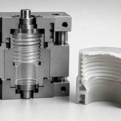
Threaded plastic components are among the most challenging products to manufacture using injection molding. Unlike simple undercuts that can often be released with slides or lifters, threaded features require controlled disengagement between the molded thread and the mold core.
The most common solution is to unscrew the threaded core from the molded component. While hydraulic rack-and-pinion systems dominate many industrial applications, several alternative mechanisms have been developed to solve specific engineering challenges.
Among the most important are systems in which the threaded core simultaneously rotates and retracts during the unscrewing process. These mechanisms are particularly useful when the molded thread is deep, when stripping is impossible, or when product geometry requires precise thread disengagement.
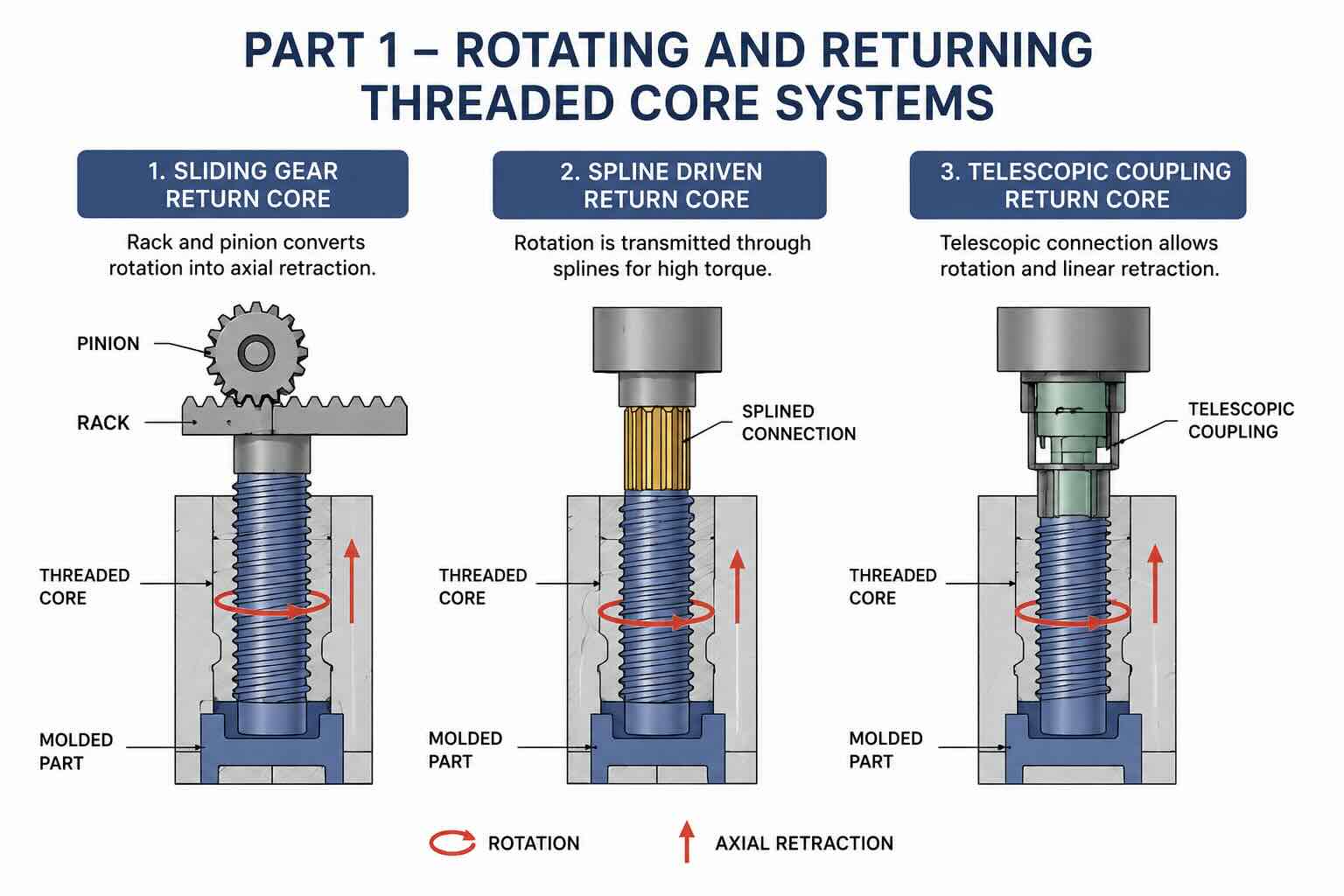
This article examines three important variants:
- Sliding Gear Return Core
- Spline Driven Return Core
- Telescopic Coupling Return Core
These mechanisms share the same objective but achieve it through different engineering solutions.
Why Rotation and Retraction Must Occur Simultaneously
Before analyzing the mechanisms themselves, it is important to understand the relationship between thread pitch and axial movement.
A threaded core cannot simply rotate inside a molded thread.
For every revolution, the core must also move axially by an amount equal to the thread pitch.
If:
Thread Pitch = 3 mm
then:
1 revolution = 3 mm axial movement
If:
Thread Length = 24 mm
then:
Number of Revolutions = 24 ÷ 3 = 8 revolutions
During those 8 revolutions the core must also retract exactly 24 mm.
Failure to synchronize rotational and axial movement will result in:
- Thread damage
- Product deformation
- Increased torque
- Mold wear
- Part sticking
This principle governs every unscrewing system discussed in this article.
Thread Travel Calculation
One of the most important calculations in unscrewing mold design is determining required core travel.
Formula:
Core Travel = Number of Threads × Pitch
Example:
Number of Threads = 6
Pitch = 4 mm
Core Travel = 6 × 4
Core Travel = 24 mm
The mechanism must therefore provide:
- 24 mm axial movement
- 6 complete revolutions
before the part can be ejected.
Torque Requirements
The second critical design parameter is unscrewing torque.
The required torque depends on:
- Plastic shrinkage
- Thread diameter
- Thread length
- Surface finish
- Mold temperature
- Draft angle
- Resin type
Typical values:
| Material | Relative Unscrewing Torque |
|---|---|
| PP | Low |
| HDPE | Low |
| ABS | Medium |
| PC | Medium |
| PA6 | High |
| Glass Filled Nylon | Very High |
For this reason, deeper threads often require larger gears, stronger bearings, and larger drive systems.
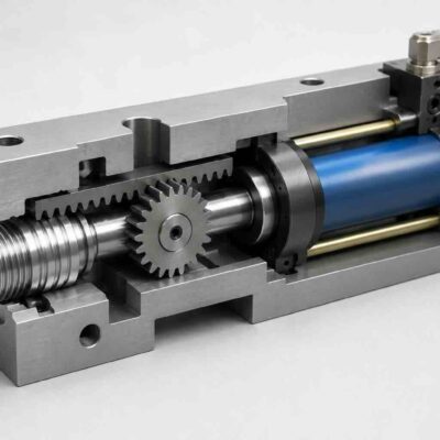
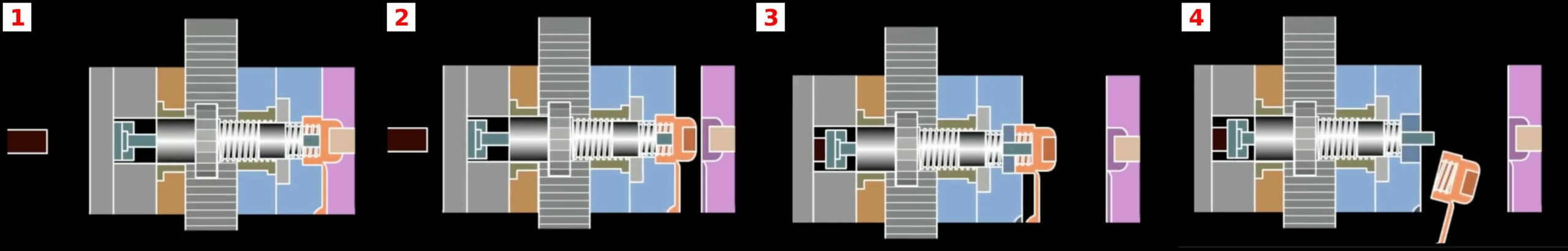
Mechanism 1 – Sliding Gear Return Core
Operating Principle
The first mechanism combines rotation and axial movement using a gear that moves together with the threaded core.
The drive rack pushes the gear.
The gear rotates the threaded mandrel.
At the same time, the mandrel moves axially backward.
Because the gear follows the mandrel during its movement, the rack must remain engaged throughout the entire travel distance.
This requires a rack wider than that used in conventional fixed-gear systems.
IMAGE PLACEHOLDER 1
Component Description
The system typically consists of:
- Threaded core
- Drive gear
- Rack
- Guide nut
- Bearings
- Mold support plates
The guide nut performs an important function.
It allows free rotation of the mandrel while maintaining precise alignment.
Without the guide nut:
- vibration increases
- tooth wear accelerates
- thread accuracy decreases
Advantages
Compact Design
Because the drive gear remains directly attached to the core, the mechanism is relatively simple.
No splines or telescopic couplings are required.
Easy Manufacturing
Most machine shops can manufacture the required components.
No specialized transmission elements are necessary.
Reduced Number of Parts
The design minimizes:
- couplings
- shafts
- support mechanisms
This often improves reliability.
Limitations
Rack Length
The main disadvantage is the large rack required.
The rack must remain engaged during the entire retraction stroke.
For long threads, rack dimensions become excessive.
Gear Alignment
Because the gear moves axially, maintaining perfect engagement becomes increasingly difficult as stroke length increases.
Wear
The extended engagement length increases:
- tooth wear
- lubrication requirements
- maintenance frequency
Practical Example
Assume:
Thread Diameter = 40 mm
Pitch = 4 mm
Thread Length = 32 mm
Required Revolutions:
32 ÷ 4 = 8 revolutions
Required Retraction:
32 mm
The rack must remain engaged throughout the complete 32 mm travel.
As a result, the rack length becomes significantly larger than in fixed-gear systems.
Mechanism 2 – Spline Driven Return Core
Operating Principle
The second design solves the main limitation of the previous mechanism.
The gear remains stationary.
Only the threaded core moves axially.
Torque is transmitted through a spline connection.
The spline allows the core to slide while continuously transmitting rotational motion.
This arrangement eliminates the need for a moving gear.
IMAGE PLACEHOLDER 2

How Splines Work
A spline consists of:
- external teeth
- internal grooves
The two components slide axially while remaining rotationally locked.
This provides:
- torque transmission
- axial freedom
- accurate alignment
The same principle is commonly used in:
- automotive drive shafts
- industrial transmissions
- machine tools
Advantages
Long Stroke Capability
This is the primary advantage.
Since the gear remains fixed:
- rack length is minimized
- gear engagement remains constant
Long thread depths become practical.
Improved Reliability
The gear no longer experiences axial movement.
This reduces:
- bearing loads
- tooth wear
- alignment problems
Higher Torque Capacity
Spline systems generally transmit greater torque than moving gear systems.
Design Considerations
Spline length must exceed:
Maximum Core Stroke + Safety Margin
Example:
Core Stroke = 40 mm
Safety Margin = 10 mm
Required Spline Length:
40 + 10
= 50 mm
Failure to provide sufficient spline overlap may result in:
- spline disengagement
- excessive wear
- catastrophic failure
Typical Applications
Spline systems are commonly found in:
- cosmetic closures
- medical packaging
- industrial threaded housings
- large caps
- deep threaded components
Mechanism 3 – Telescopic Coupling Return Core
Operating Principle
The third mechanism uses a telescopic coupling instead of a spline.
The gear remains stationary.
The threaded core retracts axially.
The telescopic coupling extends and contracts while transmitting torque.
Functionally, the system achieves the same objective as the spline design.
However, the mechanical implementation differs.
IMAGE PLACEHOLDER 3

Why Use a Telescopic Coupling?
Some applications require:
- greater stroke length
- easier assembly
- simplified maintenance
A telescopic coupling may offer advantages over long spline shafts.
The coupling absorbs movement while maintaining rotational transmission.
Advantages
Simplified Assembly
The coupling can often be installed more easily than a long spline shaft.
Reduced Machining Cost
In some designs:
- spline grinding
- spline broaching
- precision spline manufacturing
can be eliminated.
Flexible Design
The coupling can accommodate slight misalignment and manufacturing tolerances.
Limitations
Additional Components
Compared with spline systems:
- more moving parts
- more wear points
- more maintenance
are generally required.
Torque Capacity
Very high torque applications may favor spline designs.
Comparison of the Three Systems
| Feature | Sliding Gear | Spline Drive | Telescopic Coupling |
| Complexity | Low | Medium | Medium |
| Manufacturing Cost | Low | Medium | Medium |
| Long Stroke Capability | Limited | Excellent | Excellent |
| Torque Capacity | Medium | High | Medium |
| Maintenance | Low | Low | Medium |
| Gear Movement | Yes | No | No |
| Rack Length | Long | Short | Short |
Engineering Selection Guidelines
In general:
Choose the Sliding Gear System when:
- thread depth is moderate
- simplicity is important
- budget is limited
Choose the Spline System when:
- stroke is long
- torque is high
- reliability is critical
Choose the Telescopic Coupling System when:
- assembly flexibility is required
- stroke is long
- manufacturing simplicity is preferred
Conclusion
Rotating and returning threaded core systems represent some of the most efficient solutions for releasing deep molded threads. While all three mechanisms achieve simultaneous rotation and retraction, their engineering characteristics differ significantly.
The sliding gear system offers simplicity and low cost. The spline-driven system provides superior performance for long strokes and high torque. The telescopic coupling system introduces additional flexibility while maintaining compact mold construction.