Most unscrewing systems simultaneously rotate and retract the threaded core. As explained in Part 1, this approach follows the natural geometry of the thread and minimizes friction between the molded part and the core.
However, there are situations where axial retraction of the threaded core is unnecessary, undesirable, or mechanically difficult to implement.
In these cases, engineers may choose a different strategy:
The threaded core rotates, but does not move axially.
Instead, the molded part remains stationary through specially designed anti-rotation features. As the core rotates, the molded component gradually unscrews itself from the thread.
This family of mechanisms offers significant advantages:
- Lower mold complexity
- Reduced number of moving components
- Lower manufacturing cost
- Simplified maintenance
- Smaller mold size
The challenge is preventing the molded part from rotating together with the core.
Three common solutions exist:
- External Anti-Rotation Pattern
- Internal Anti-Rotation Pattern
- Top Stop Anti-Rotation Pattern
Although these systems appear simple, successful implementation requires careful engineering.
Understanding the Principle
To understand these mechanisms, imagine removing a nut from a bolt.
Normally:
- the bolt remains fixed
- the nut rotates
In these mold designs:
- the molded part behaves like the nut
- the threaded core behaves like the bolt
The molded part must remain stationary while the core rotates.
If both rotate together:
No unscrewing occurs.
This is the fundamental engineering challenge.
Why Use Rotating-Only Systems?
The obvious question is:
Why eliminate core retraction?
Several reasons exist.
Reduced Mold Complexity
A retracting core requires:
- guide systems
- bearings
- spline shafts
- telescopic couplings
- moving gears
A rotating-only system eliminates many of these components.
Reduced Mold Size
Without axial movement:
- fewer support plates are needed
- shorter mold depth is possible
- cooling channels become easier to design
Lower Cost
Fewer components mean:
- lower manufacturing costs
- lower maintenance costs
- fewer replacement parts
Higher Reliability
Every moving component introduces potential failure points.
Simpler mechanisms often survive millions of cycles with minimal maintenance.
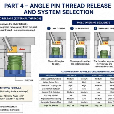
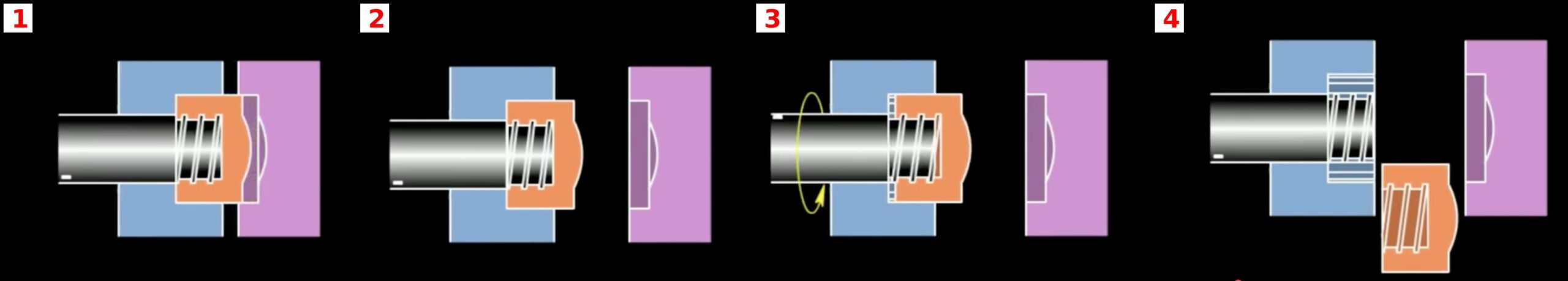
Mechanism 4 – External Anti-Rotation Design
Operating Principle
In this design, anti-rotation features are placed on the outside surface of the molded part.
The product is prevented from rotating while the threaded core turns.
Typical anti-rotation features include:
- knurls
- ribs
- flats
- splines
- polygonal profiles
As the core rotates, the thread disengages progressively.
The molded part remains stationary because the anti-rotation geometry is captured by mold features.
IMAGE PLACEHOLDER 4
Common Product Examples
Typical applications include:
- cosmetic caps
- detergent closures
- industrial caps
- threaded covers
Many packaging components already contain external grip patterns, making this solution highly attractive.
Design Requirements
The anti-rotation geometry must resist unscrewing torque.
The minimum holding torque should exceed:
Required Holding Torque > Unscrewing Torque × Safety Factor
A safety factor of 1.5 to 2 is typically recommended.
Advantages
Simple Mold Construction
No retracting mechanism is required.
Lower Manufacturing Cost
Fewer components must be machined.
Easy Maintenance
Reduced wear points improve service life.
Potential Problems
If the external pattern is insufficient:
- product slipping may occur
- incomplete unscrewing may result
- thread damage may appear
Proper anti-rotation design is therefore critical.
Calculating Required Anti-Rotation Force
The force required to prevent rotation can be estimated.
Formula:
T = F × R
Where:
T = Torque
F = Holding Force
R = Effective Radius
Example:
Unscrewing Torque = 4 N·m
Effective Radius = 20 mm
Convert radius:
20 mm = 0.02 m
Holding Force:
F = T ÷ R
F = 4 ÷ 0.02
F = 200 N
The anti-rotation feature must therefore resist at least 200 N.
Using a safety factor of 2:
Required Holding Force = 400 N
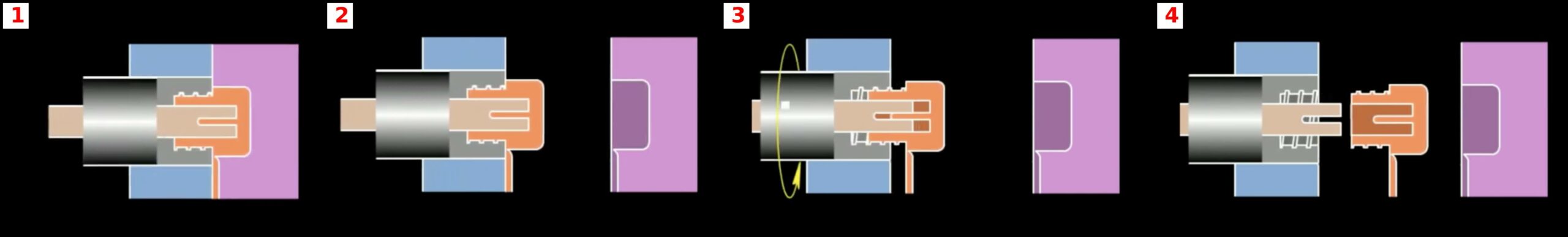
Mechanism 5 – Internal Anti-Rotation Design
Operating Principle
This mechanism uses internal features instead of external ones.
The molded part contains:
- ribs
- slots
- internal splines
- internal flats
These features engage mold elements that prevent rotation.
The threaded core rotates while the product remains fixed.
IMAGE PLACEHOLDER 5
Why Use Internal Features?
Many consumer products require smooth external surfaces.
For example:
- cosmetic packaging
- medical containers
- luxury consumer products
External ribs may be unacceptable.
Internal anti-rotation allows the exterior to remain visually clean.
Engineering Challenges
Internal anti-rotation features often provide less leverage.
The effective radius is smaller.
As a result:
Required Holding Force increases.
Example:
Unscrewing Torque = 4 N·m
Internal Radius = 10 mm
F = 4 ÷ 0.01
F = 400 N
Compared to the previous example:
External Radius = 20 mm → 200 N
Internal Radius = 10 mm → 400 N
The required force doubles.
This demonstrates why internal anti-rotation systems must be carefully designed.
Advantages
Better Appearance
External surfaces remain untouched.
Consumer Product Friendly
Ideal for premium packaging.
Hidden Functional Features
Anti-rotation geometry is invisible to end users.
Limitations
Higher Stress Concentrations
Internal features may experience higher loading.
More Difficult Mold Design
Additional inserts may be required.
Increased Manufacturing Precision
Tolerances become more critical.
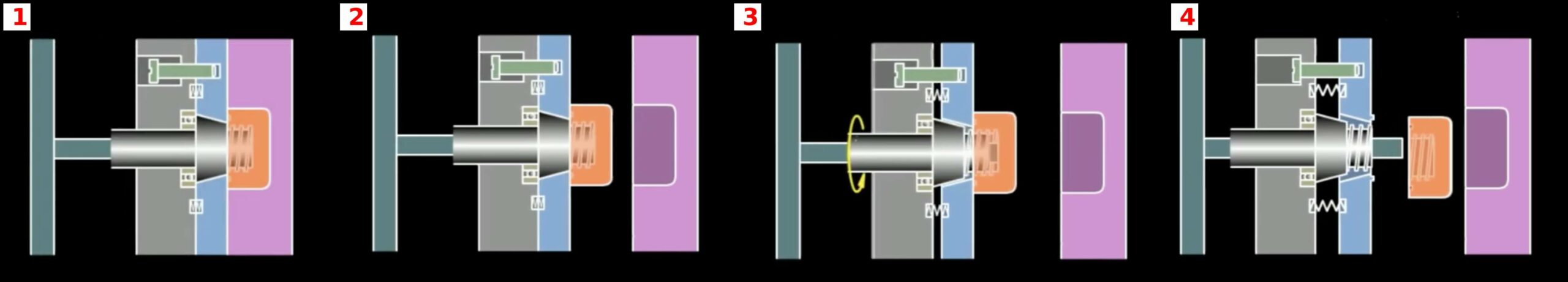
Mechanism 6 – Top Stop Anti-Rotation Design
Operating Principle
The third variation prevents rotation using features located on the top surface of the molded component.
Instead of external or internal ribs, the product engages a stop surface.
As the threaded core rotates:
- the stop feature prevents rotation
- the product gradually disengages
IMAGE PLACEHOLDER 6
Typical Applications
Common examples include:
- shallow threaded closures
- threaded plugs
- electronic housings
- low-torque applications
Stop Surface Design
The stop surface must withstand:
- torque loading
- repeated cycling
- wear
Sharp corners should be avoided.
Stress concentration may cause:
- plastic deformation
- cracking
- premature wear
Wear Analysis
The contact area strongly influences durability.
Formula:
Contact Pressure = Force ÷ Area
Example:
Force = 300 N
Contact Area = 60 mm²
Pressure:
300 ÷ 60
= 5 N/mm²
Increasing contact area reduces pressure and extends tool life.
Comparing the Three Anti-Rotation Methods
| Feature | External Pattern | Internal Pattern | Top Stop |
|---|---|---|---|
| Mold Complexity | Low | Medium | Low |
| Product Appearance | Visible Pattern | Hidden Pattern | Hidden Pattern |
| Torque Capacity | High | Medium | Low |
| Cost | Low | Medium | Low |
| Reliability | High | High | Medium |
| Suitable for Premium Products | Medium | Excellent | Good |
Engineering Selection Guidelines
Use External Anti-Rotation when:
- high torque is required
- external ribs already exist
- appearance is not critical
Use Internal Anti-Rotation when:
- aesthetics are important
- premium products are produced
- hidden functionality is desired
Use Top Stop Systems when:
- thread torque is low
- simplicity is critical
- production cost must be minimized
Common Design Mistakes
Several failures are repeatedly observed in production molds.
Insufficient Holding Geometry
The most common error.
The molded part begins rotating with the core.
Underestimating Shrinkage
Shrinkage increases thread friction.
Actual torque often exceeds theoretical calculations.
Ignoring Wear
Anti-rotation features may function perfectly during sampling but degrade after millions of cycles.
Poor Surface Finish
Rough thread surfaces increase unscrewing torque dramatically.
Economic Comparison
Compared with retracting-core systems discussed in Part 1:
Rotating-only systems generally offer:
- lower tooling cost
- shorter build time
- easier maintenance
- smaller mold size
However, they require:
- suitable product geometry
- reliable anti-rotation features
- careful torque analysis
The choice should always be based on both product design and production requirements.
Conclusion
Rotating threaded cores without axial retraction represent one of the simplest and most cost-effective approaches to thread release in injection molds. By preventing the molded part from rotating, the core can unscrew the thread without requiring complex retracting mechanisms.
External anti-rotation patterns provide the highest torque capacity, internal anti-rotation systems offer superior aesthetics, and top-stop designs deliver maximum simplicity for low-torque applications.