Traditional unscrewing molds typically require a dedicated drive system. Whether hydraulic, pneumatic, electric, or mechanical, some external source of power must generate the rotational motion needed to release the molded thread.
However, not all applications justify the complexity and cost of a fully driven unscrewing mechanism.
For products with:
- short threads,
- moderate production volumes,
- limited mold space,
- cost-sensitive projects,
engineers have developed alternative systems that use the mold’s own movements to generate thread release.
These solutions are particularly attractive because they eliminate:
- hydraulic cylinders,
- servo motors,
- rotary actuators,
- complex gearboxes.
This article examines two of the most ingenious examples:
- Intermittent Unscrewing Using an Angle Slider
- Automatic Unscrew Thread Mold
Although both systems achieve thread release without dedicated rotary drives, they operate according to very different engineering principles.
Why Eliminate Dedicated Rotary Drives?
Before examining the mechanisms themselves, it is useful to understand why mold designers seek alternatives to conventional unscrewing systems.
Traditional unscrewing systems increase:
- mold cost,
- mold size,
- maintenance requirements,
- assembly complexity.
A hydraulic unscrewing unit may require:
- cylinder,
- rack,
- gear,
- bearings,
- guides,
- sensors,
- hydraulic connections.
Each component introduces:
- additional machining,
- additional tolerance stack-up,
- additional failure points.
For many products, this complexity cannot be economically justified.
The systems discussed in this article use energy already available during mold opening and ejection.
This dramatically simplifies mold construction.
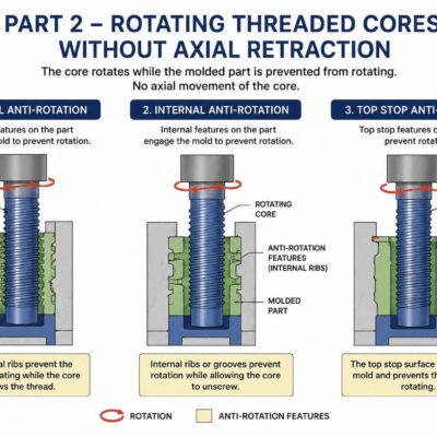
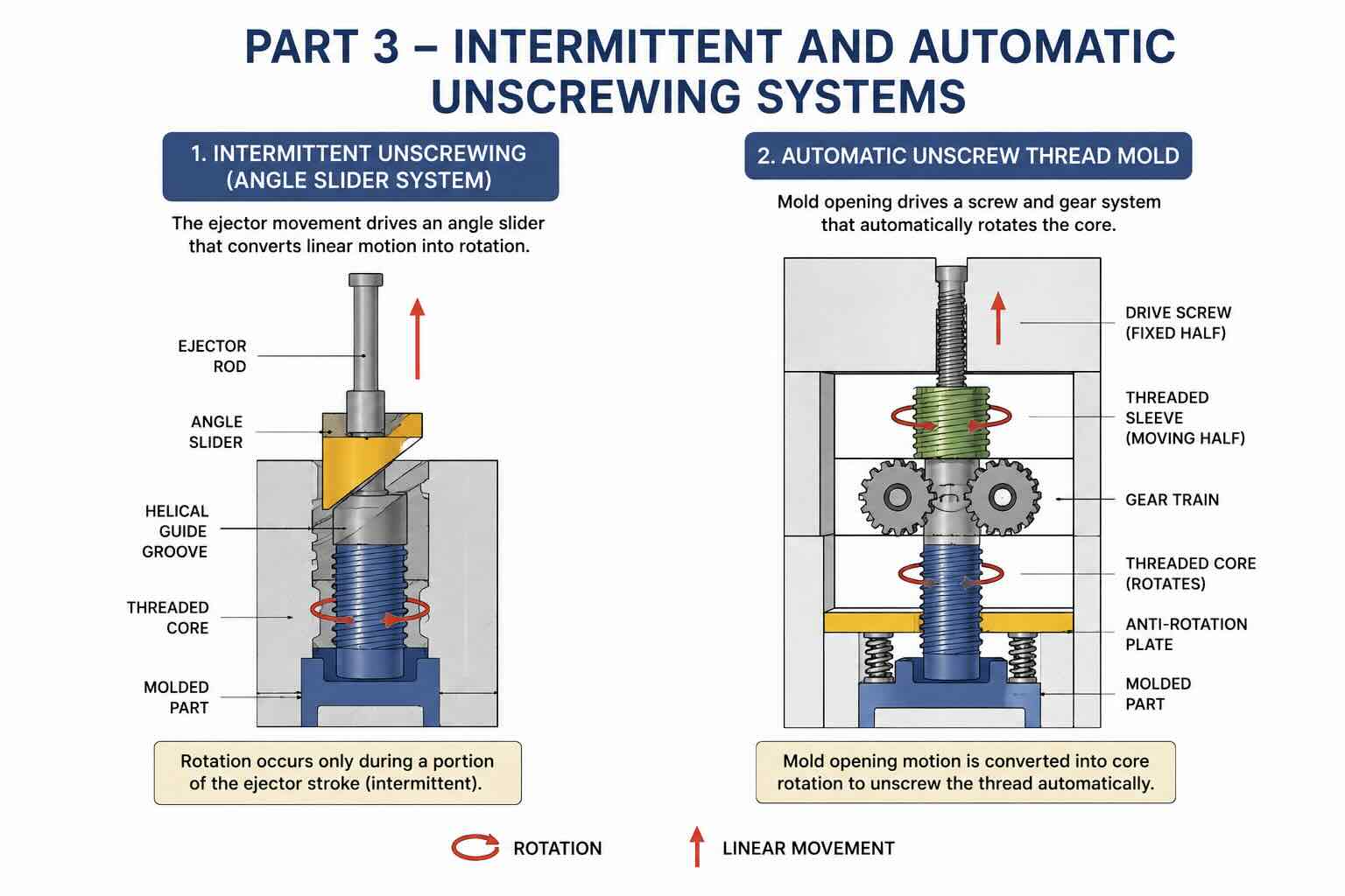
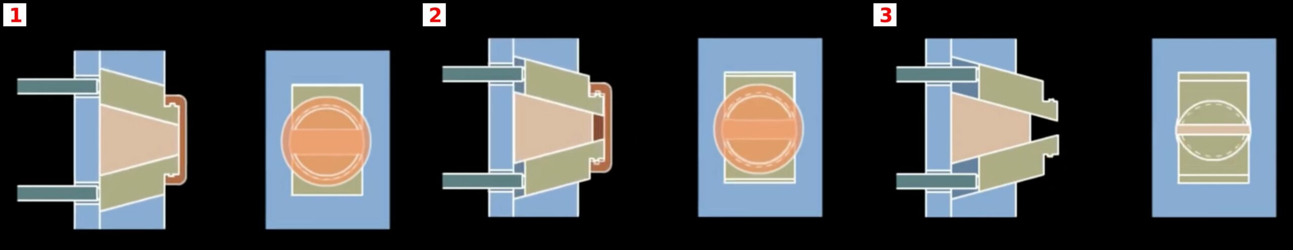
Mechanism 7 – Intermittent Unscrewing Using an Angle Slider
Operating Principle
This mechanism is one of the most elegant examples of converting linear motion into rotational motion without using gears.
After mold opening:
- the ejector system begins moving forward,
- the ejector rod drives an inclined slider,
- the slider follows a helical guide groove,
- the guide groove forces simultaneous rotation and axial movement,
- the threaded core disengages from the molded thread.
Unlike conventional unscrewing systems, rotation occurs only during a limited portion of the ejector stroke.
For this reason, the mechanism is called:
Intermittent Unscrewing.
IMAGE PLACEHOLDER 7
Understanding the Helical Groove
The heart of the system is the helical guide groove.
The groove functions similarly to a screw thread.
As the slider moves linearly:
the groove geometry forces rotational displacement.
The relationship between linear travel and rotation is determined by the helix angle.
A steeper helix produces:
- more rotation,
- higher forces,
- greater wear.
A shallower helix produces:
- less rotation,
- smoother operation,
- lower stresses.
Proper groove design is therefore critical.
Rotation Calculation
The required rotational angle depends on thread geometry.
Formula:
Required Revolutions = Thread Length ÷ Pitch
Example:
Thread Length = 12 mm
Pitch = 2 mm
Required Revolutions:
12 ÷ 2 = 6 Revolutions
Total Rotation:
6 × 360°
= 2160°
The groove must therefore generate 2160 degrees of rotation before the thread is completely released.
Groove Travel Calculation
The ejector stroke must provide sufficient travel to generate the required rotation.
Formula:
Groove Travel = Required Revolutions × Lead
Example:
Lead = 5 mm
Required Revolutions = 6
Groove Travel:
6 × 5
= 30 mm
The ejector system must therefore provide at least 30 mm of effective travel.
Advantages
Extremely Compact Design
No gear train is required.
No rotary actuator is required.
No hydraulic cylinder is required.
This makes the mechanism particularly attractive for small molds.
Low Manufacturing Cost
Compared with hydraulic unscrewing systems:
- fewer components,
- less machining,
- reduced assembly time.
Tooling costs can be significantly lower.
Simplified Maintenance
Because there are fewer moving components:
- lubrication requirements are reduced,
- failure points are minimized,
- maintenance intervals are extended.
Limitations
Despite its elegance, the mechanism has several limitations.
Limited Thread Length
The available ejector stroke limits rotation.
Very deep threads are generally impractical.
High Contact Stress
The slider and groove experience concentrated loads.
Repeated cycling may cause:
- wear,
- galling,
- dimensional changes.
Sensitivity to Tolerances
Poor machining accuracy can produce:
- binding,
- uneven rotation,
- premature wear.
Typical Applications
The system is commonly used for:
- packaging closures,
- cosmetic caps,
- disposable medical products,
- consumer goods.
It is particularly attractive when:
production volumes are moderate and mold simplicity is important.
Wear Analysis
The guide groove is the most critical wear area.
Factors affecting wear include:
- contact pressure,
- lubrication quality,
- surface hardness,
- cycle frequency.
Recommended materials include:
- hardened tool steel,
- nitrided steel,
- coated components.
Common coatings include:
- TiN
- TiCN
- DLC
These treatments significantly improve service life.
Mechanism 8 – Automatic Unscrew Thread Mold
Operating Principle
The automatic unscrew thread mold is one of the most ingenious mechanical solutions ever developed for threaded components.
Instead of using:
- motors,
- cylinders,
- external drives,
the mechanism uses the opening movement of the mold itself as the power source.
The mold generates its own unscrewing motion automatically.
IMAGE PLACEHOLDER 8
![]()
Sequence of Operation
The process occurs as follows.
Step 1 – Molded Part Formation
The threaded core forms the internal thread during injection.
The molded part remains attached to the moving half of the mold.
Step 2 – Mold Opening
The mold begins to open.
Relative movement occurs between:
- fixed side,
- moving side.
This movement becomes the energy source for the system.
Step 3 – Screw Engagement
A stationary screw attached to the fixed half engages a threaded sleeve mounted on the moving half.
As the mold opens:
the screw forces the sleeve to rotate.
Step 4 – Gear Rotation
The rotating sleeve drives:
- gears,
- shafts,
- threaded core.
The core begins unscrewing from the molded component.
Step 5 – Anti-Rotation Plate Action
A spring-loaded pressure plate contacts the molded part.
Its function is critical.
Without it:
the product would rotate together with the core.
The pressure plate prevents rotation and allows thread release.
Step 6 – Complete Thread Release
Once sufficient rotation has occurred:
the molded part is completely separated from the threaded core.
Normal ejection can then take place.
Why This System Is Unique
Most unscrewing systems require a dedicated energy source.
This design uses:
Mold Opening Movement = Drive Energy
As a result:
- no hydraulic power,
- no electrical power,
- no separate drive mechanism.
The mold becomes self-powered.
Rotation Ratio Calculation
The amount of core rotation depends on:
- screw pitch,
- opening distance,
- gear ratio.
Formula:
Core Revolutions =
(Mold Opening Stroke ÷ Screw Pitch) × Gear Ratio
Example:
Opening Stroke = 120 mm
Screw Pitch = 6 mm
Gear Ratio = 2:1
Core Revolutions:
120 ÷ 6 = 20
20 × 2
= 40 Revolutions
This may be more than sufficient for many packaging applications.
Advantages
Fully Automatic
No external control system required.
Reduced Maintenance
No hydraulic leaks.
No electric motors.
No sensors.
Lower Operating Cost
Energy consumption is essentially zero.
The mold opening movement already exists.
High Reliability
Fewer active components generally increase reliability.
Limitations
Design Complexity
Although operation is simple, design requires:
- precise geometry,
- accurate synchronization,
- careful tolerance control.
Limited Flexibility
Rotation is directly linked to mold opening distance.
Adjustments are more difficult than in servo-driven systems.
Not Suitable for Every Product
Very high torque applications may exceed the capability of purely mechanical systems.
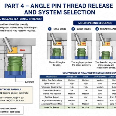
Comparing the Two Systems
| Feature | Angle Slider | Automatic Unscrew Mold |
|---|---|---|
| Rotary Drive Required | No | No |
| Hydraulic Cylinder | No | No |
| Electric Motor | No | No |
| Manufacturing Cost | Low | Medium |
| Complexity | Low | Medium |
| Long Threads | Limited | Good |
| Maintenance | Low | Low |
| Reliability | High | High |
Engineering Selection Guidelines
Choose the Intermittent Angle Slider when:
- threads are shallow,
- mold space is limited,
- cost reduction is critical.
Choose the Automatic Unscrew Mold when:
- production volumes are high,
- complete automation is required,
- sufficient mold opening stroke is available.
Conclusion
Intermittent unscrewing systems and automatic self-driven thread molds demonstrate that effective thread release does not always require hydraulic cylinders or electric motors. By intelligently converting existing mold movements into rotational motion, these mechanisms achieve reliable thread release with remarkable simplicity.
For many packaging, consumer, and medical applications, these solutions offer a compelling combination of low cost, high reliability, and compact mold design.