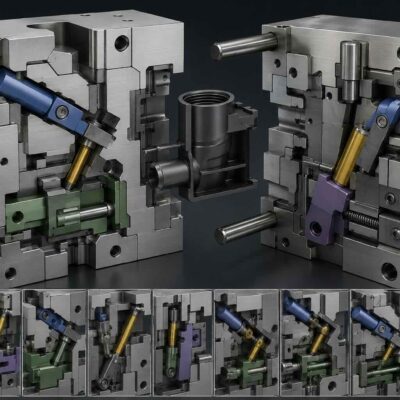
Introduction
The previous parts of this series examined eight advanced thread release mechanisms that eliminate or simplify conventional hydraulic and motor-driven unscrewing systems.
We analyzed:
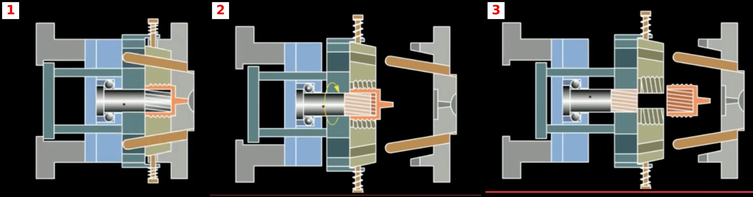
- Sliding Gear Return Cores
- Spline Driven Return Cores
- Telescopic Coupling Return Cores
- External Anti-Rotation Systems
- Internal Anti-Rotation Systems
- Top Stop Systems
- Intermittent Angle Slider Unscrewing
- Automatic Unscrew Thread Molds
The final mechanism belongs to a completely different category.
Unlike all previous systems, it does not unscrew the thread at all.
Instead, it removes the thread geometry from the molded component by moving a mold segment away from the product.
For specific external thread designs, this solution can eliminate:
- rotating cores,
- hydraulic cylinders,
- gear systems,
- rack-and-pinion mechanisms,
- servo drives.
As a result, it is often one of the simplest and most economical thread release solutions available.
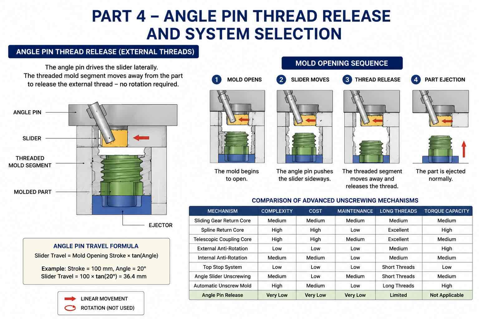
Mechanism 9 – Angle Pin Release for External Threads
Operating Principle
This mechanism uses a conventional angle pin and slider arrangement.
When the mold opens:
- the angle pin engages the slider,
- the slider moves laterally,
- the threaded mold segment withdraws,
- the external thread geometry is released,
- the molded part can be ejected.
Unlike conventional unscrewing systems:
there is no rotational motion.
The thread is released by removing the cavity surface that created the thread.
IMAGE PLACEHOLDER 9
Why This Method Works
Many external threads do not require true unscrewing.
If:
- thread depth is limited,
- thread profile is favorable,
- shrinkage is manageable,
the threaded geometry can simply be withdrawn laterally.
The slider effectively removes the undercut created by the thread.
Once the threaded section has been removed:
the product behaves like a conventional molded component.
Typical Applications
This system is commonly found in:
Packaging Components
- threaded caps
- closures
- dispensing systems
Consumer Products
- battery housings
- electronic covers
- protective caps
Automotive Components
- sensor covers
- threaded protective housings
Industrial Components
- protective plugs
- threaded covers
- service access caps
Mold Opening Sequence
Understanding the opening sequence is critical.
Step 1 – Mold Opens
The moving half begins separating from the fixed half.
The angle pin remains engaged with the slider.
Step 2 – Slider Movement
The angle pin forces the slider to move sideways.
The threaded cavity section starts disengaging.
Step 3 – Thread Release
The thread-forming section moves away from the molded component.
The thread is no longer trapped.
Step 4 – Product Ejection
Normal ejectors remove the part.
No additional unscrewing movement is required.
Angle Pin Design Considerations
The angle pin is responsible for generating the slider movement.
The relationship between mold opening stroke and slider travel depends on the pin angle.
Formula:
Slider Travel = Mold Opening Stroke × tan(Angle)
Example:
Opening Stroke = 100 mm
Angle Pin = 20°
Slider Travel:
100 × tan(20°)
= 36.4 mm
This means that 100 mm of mold opening generates approximately 36 mm of lateral slider movement.
Selecting the Angle Pin Angle
Typical values:
| Angle Pin | Application |
|---|---|
| 10°–15° | Heavy sliders |
| 15°–20° | General purpose |
| 20°–25° | Fast release |
| Above 25° | Special applications |
Most mold designers select:
15°–20°
because it provides a good balance between:
- force transmission
- wear resistance
- smooth operation
Determining Required Slider Travel
The minimum travel must completely clear the threaded geometry.
Formula:
Minimum Slider Travel =
Thread Depth + Safety Clearance
Example:
Thread Depth = 6 mm
Safety Clearance = 2 mm
Required Travel:
6 + 2
= 8 mm
The slider must therefore move at least 8 mm before ejection begins.
Advantages of Angle Pin Thread Release
Extremely Simple Design
No rotary components.
No gears.
No splines.
No telescopic couplings.
No hydraulic cylinders.
Low Manufacturing Cost
The mechanism uses standard mold components.
Many mold makers already use angle pins and sliders extensively.
Fast Cycle Time
No additional unscrewing motion is required.
The thread is released during normal mold opening.
Reduced Maintenance
Fewer moving parts result in:
- lower wear,
- easier servicing,
- lower operating costs.
Limitations
Despite its simplicity, the system is not suitable for every thread design.
Limited Thread Depth
Deep threads usually require true unscrewing.
Product Geometry Restrictions
Certain thread profiles cannot be released using lateral movement alone.
High Side Loads
Large sliders may create significant side forces.
Proper guidance becomes critical.
Wear Considerations
The highest wear areas are:
- angle pin surfaces,
- slider guides,
- locking surfaces.
Recommended materials:
- hardened tool steel
- nitrided steel
- coated wear plates
Proper lubrication dramatically extends service life.
Comparison of All Nine Advanced Mechanisms
The following table summarizes the engineering characteristics of all systems discussed throughout this series.
| Mechanism | Complexity | Cost | Maintenance | Long Threads | Torque Capacity |
| Sliding Gear Return Core | Medium | Medium | Medium | Medium | Medium |
| Spline Return Core | High | High | Low | Excellent | High |
| Telescopic Coupling Core | High | High | Medium | Excellent | Medium |
| External Anti-Rotation | Low | Low | Low | Medium | High |
| Internal Anti-Rotation | Medium | Medium | Low | Medium | Medium |
| Top Stop System | Low | Low | Low | Short Threads | Low |
| Angle Slider Unscrewing | Medium | Low | Medium | Short Threads | Medium |
| Automatic Unscrew Mold | High | Medium | Low | Long Threads | High |
| Angle Pin Release | Very Low | Very Low | Very Low | Limited | Not Applicable |
Cost Ranking
From lowest to highest tooling cost:
- Angle Pin Release
- Top Stop System
- External Anti-Rotation
- Angle Slider Unscrewing
- Internal Anti-Rotation
- Sliding Gear Return Core
- Automatic Unscrew Mold
- Telescopic Coupling System
- Spline Driven System
Reliability Ranking
For long production runs:
- External Anti-Rotation
- Angle Pin Release
- Automatic Unscrew Mold
- Spline Driven System
- Internal Anti-Rotation
- Sliding Gear Return Core
- Telescopic Coupling System
- Angle Slider Unscrewing
- Top Stop System
Actual performance will always depend on:
- design quality,
- manufacturing precision,
- maintenance practices.
Selection Guidelines
Choose a Spline Return Core when:
- thread length is significant,
- torque is high,
- reliability is critical.
Choose a Telescopic Coupling System when:
- long travel is required,
- assembly flexibility is important.
Choose External Anti-Rotation when:
- product geometry already contains external ribs,
- cost reduction is a priority.
Choose Internal Anti-Rotation when:
- product appearance is critical.
Choose an Angle Slider System when:
- thread depth is moderate,
- compact mold construction is required.
Choose an Automatic Unscrew Mold when:
- production volume is high,
- complete automation is desired.
Choose an Angle Pin Release System when:
- thread geometry permits lateral release,
- simplicity is the primary objective.
Future Trends
Modern mold design is increasingly moving toward:
Servo-Driven Unscrewing
Benefits include:
- programmable rotation
- adjustable speed
- precise positioning
Smart Monitoring Systems
Future molds will monitor:
- torque
- wear
- cycle count
- lubrication condition
Hybrid Systems
Combining:
- mechanical release
- servo assistance
- automated monitoring
to maximize efficiency.
IMAGE PLACEHOLDER 12
[INSERT IMAGE – FUTURE SERVO UNSCREWING TECHNOLOGY]
Final Conclusion
Advanced unscrewing mechanisms provide mold designers with a wide range of alternatives beyond traditional hydraulic and motor-driven systems. Each mechanism offers a unique balance between cost, complexity, reliability, maintenance requirements, and application range.
There is no universal solution.
The optimal choice depends on:
- thread geometry,
- product material,
- production volume,
- mold size,
- maintenance strategy,
- economic constraints.
Engineers who understand the strengths and limitations of these nine advanced mechanisms can often reduce tooling cost, simplify mold construction, improve reliability, and shorten cycle times while maintaining excellent product quality.
The most successful mold designs are rarely the most complex. In many cases, the simplest mechanism capable of reliably releasing the thread will provide the best long-term manufacturing performance.