Introduction
One of the most common mistakes in hydraulic cylinder sizing for injection molds is surprisingly simple.
The engineer performs all the calculations correctly.
The adhesion coefficient is appropriate.
The number of cavities is correct.
The extraction force is divided correctly among multiple cylinders.
Yet the selected hydraulic cylinder proves to be dramatically undersized during production.
Why?
Because the calculation starts from the wrong geometric assumption.
Many engineers calculate only the visible lateral surface of the molded component, forgetting that molten plastic adheres to every surface that remains in contact with the part during ejection—including threads, grooves, undercuts, and other detailed geometries.
A real engineering case analyzed by the Vega Technical Department perfectly demonstrates how overlooking a single geometric feature nearly doubled the required extraction force and completely changed the hydraulic cylinder selection.
This case also highlights an important principle confirmed by modern mold engineering references:
Hydraulic cylinder sizing begins with understanding the actual contact surface—not simply the visible geometry.
The Engineering Challenge
A mold maker contacted the Vega Technical Department requesting verification of the hydraulic cylinder sizing for a multi-cavity injection mold producing threaded plastic caps.
The mold contained:
- 16 cavities
- 4 caps extracted simultaneously
- hydraulic unscrewing system
- four hydraulic cylinders operating together
The customer had already completed all extraction force calculations and proposed using a CM050 hydraulic cylinder operating at only 85 bar.
At first glance, the calculations appeared perfectly reasonable.
However, one critical assumption was incorrect.
The Customer’s Calculation
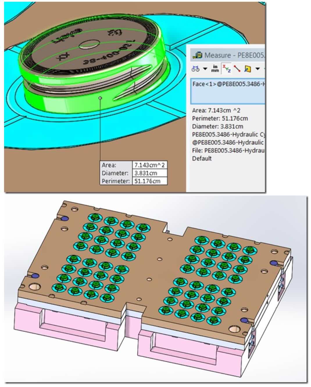
The customer measured the lateral surface of each cap directly from the CAD model.
Measured lateral area:
7.143 cm²
Since the mold produced:
16 cavities × 4 caps
the total adhesion surface became
457.152 cm²
Using a plastic adhesion coefficient of
15 kg/cm²
the customer calculated the nominal extraction force using
Result:
457.152 × 15 = 6,857 kgf
Dividing the total load among four cylinders produced
1,714 kgf per cylinder
leading to the conclusion that a CM050 hydraulic cylinder operating at 85 bar would be sufficient.
Mathematically, every calculation was correct.
The geometry was not.
The Hidden Surface That Changed Everything
After reviewing the 3D model, Stefano Rogora immediately identified the real problem.
The measured area included only the smooth cylindrical surface.
It completely ignored the thread.
During extraction, plastic does not distinguish between smooth surfaces and threaded surfaces.
Every thread flank remains in contact with the polymer until the cap has completely unscrewed.
Consequently, the actual adhesion area was not
7.143 cm²
but approximately
13.4 cm²
per cap.
This single observation completely transformed the engineering calculation.
Recalculating the Extraction Force
Actual lateral surface:
13.4 cm²
Total number of caps:
64
Total adhesion area:
13.4 × 64
= 857.6 cm²
Using the same adhesion coefficient:
15 kg/cm²
the extraction force became
857.6 × 15
= 12,864 kgf
Dividing equally among four hydraulic cylinders produced
3,216 kgf per cylinder
almost exactly double the customer’s estimate.
Why the Hydraulic Cylinder Had to Change
Once the correct extraction force had been established, the previously selected hydraulic cylinder was no longer adequate.
The Vega Technical Department recommended replacing the proposed CM050 with a CM063 hydraulic cylinder equipped with a 28/36 mm rod, operating at 140 bar.
Nothing had changed in the mold.
Nothing had changed in the plastic.
Nothing had changed in the hydraulic circuit.
Only one geometric parameter had been corrected.
Yet the required cylinder became dramatically larger.
Why Threads Increase Extraction Force
This engineering principle is often underestimated.
Plastic adhesion develops wherever polymer remains in intimate contact with steel.
A threaded profile contains:
- flank surfaces
- root surfaces
- crest surfaces
- continuously changing contact angles
The total contact area is therefore much larger than the projected cylindrical area.
The deeper the thread,
the greater the real adhesion surface.
Consequently,
threaded parts frequently require significantly larger hydraulic cylinders than smooth cylindrical components having exactly the same outside diameter.
Surface Area Is More Important Than Projected Area
Many extraction calculations begin with projected geometry.
However, extraction force depends on
real contact surface
rather than projected surface.
Typical features increasing extraction force include:
- external threads
- internal threads
- grooves
- ribs
- knurling
- textured surfaces
- undercuts
- sealing profiles
Every additional square millimeter of contact contributes to plastic adhesion.
Ignoring these features inevitably produces an undersized hydraulic cylinder.
Plastic Adhesion Is Only Part of the Story
Even after calculating the correct adhesion force, the hydraulic cylinder should never be sized using theoretical values alone.
The Vega Technical Manual explains that additional forces originate from:
- guide friction
- side loads
- oil compressibility
- alignment errors
- elastic deformation
- pressure spikes
- synchronization errors
- contamination
- hydraulic pressure losses.
These factors explain why practical engineering always includes appropriate safety margins.
Multiple Cylinders Require Proper Load Distribution
This mold used four hydraulic cylinders operating simultaneously.
Although dividing the total extraction force equally seems straightforward, real systems rarely distribute loads perfectly.
The Summit Polymers Injection Mold Tooling Standards Manual specifically recommends using flow dividers and hydraulic synchronization systems whenever multiple cylinders operate together to ensure balanced movement and equal load sharing.
Without proper synchronization:
- one cylinder may become overloaded;
- another may contribute very little;
- guide wear increases;
- mold life decreases.
What Modern Mold Design Teaches
The Injection Mold Design Handbook emphasizes that mold engineering combines mechanics, materials science, heat transfer, manufacturing tolerances, and machine dynamics into a single integrated system.
Hydraulic cylinder sizing therefore cannot rely on isolated calculations.
It requires understanding how the molded part interacts with steel throughout the complete molding cycle.
This engineering philosophy perfectly explains why apparently minor geometric details—such as a thread profile—can fundamentally change hydraulic requirements.
The Vega Engineering Approach
Rather than accepting the customer’s calculations, the Vega Technical Department carefully reviewed the physical geometry of the molded part.
Instead of asking,
“Are the equations correct?”
they asked,
“Is the geometry correct?”
That difference represents true engineering.
The equations never changed.
The geometry did.
And the hydraulic cylinder changed with it.
Lessons Learned
1. Hydraulic cylinder sizing always starts with the actual contact surface.
2. Visible geometry is rarely the complete geometry.
3. Threads significantly increase plastic adhesion.
4. Theoretical extraction force should always include appropriate safety margins.
5. Multiple hydraulic cylinders require proper synchronization.
6. Geometry determines hydraulic force.
7. Correct engineering begins with understanding the molded part—not simply solving equations.
Conclusion
This real engineering case demonstrates that successful hydraulic cylinder sizing depends as much on geometric interpretation as on mathematical calculation.
The customer’s equations were correct.
The adhesion coefficient was reasonable.
The load distribution among four cylinders was properly calculated.
Only one assumption was incorrect:
the measured surface area did not represent the actual contact area between the plastic and the mold.
By identifying this overlooked geometric detail, the Vega Technical Department almost doubled the required extraction force and recommended a completely different hydraulic cylinder.
This case reminds every mold designer of one essential engineering principle:
Hydraulic cylinders are sized by the surfaces that actually touch the plastic—not by the surfaces that are easiest to measure.