Introduction
In hydraulic cylinder sizing for injection molds, there is one situation that challenges even highly experienced mold designers.
The cylinder is selected using the correct engineering formulas, the theoretical extraction force appears more than sufficient, the calculations are validated, and yet, during mold trials, the slide refuses to move.
The most common reaction is to immediately increase the cylinder bore.
In many cases, however, this is not the real solution.
A real engineering case analyzed by the Vega Technical Department demonstrates that hydraulic cylinder sizing cannot rely solely on theoretical extraction force calculations. The actual behavior of a mold slide is influenced by numerous factors that cannot be fully predicted mathematically, including friction, machining tolerances, elastic deformation, clamping force, alignment, lubrication, and assembly conditions.
This project perfectly illustrates how practical engineering experience complements theoretical calculations and why, in injection mold hydraulics, identifying the true cause of a problem is often more important than simply applying equations.
The Real Case
A mold maker was developing an injection mold for a component manufactured in PC + 10% Glass Fiber, a material characterized by an extremely low shrinkage of approximately 1.005%.
The side slide was actuated by a CR050028 hydraulic cylinder, selected by the customer using conventional sizing calculations.
During the first production trials, however, an unexpected problem appeared.
Even when the cylinder was supplied with 140 bar hydraulic pressure, the slide remained completely locked and was unable to extract the side core.
The customer therefore contacted the Vega Technical Department asking a seemingly simple question:
“Which cylinder size should we use instead?”
The question appeared straightforward.
The answer was considerably more complex.
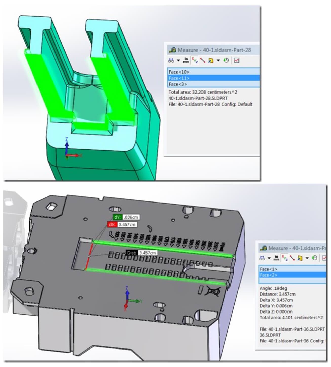
Calculating the Theoretical Extraction Force
The customer had correctly calculated the lateral surface area subjected to plastic adhesion.
The total contact area was:
32.208 + 4.101 = 36.309 cm²
For the selected material, a conservative adhesion coefficient was adopted:
K = 25 kg/cm²
The theoretical extraction force was therefore calculated using:
resulting in:
F = 36.309 × 25
F = 907.7 kgf
This value correctly represented the theoretical force required to extract the molded component without considering mechanical friction.
From a mathematical point of view, the calculation was correct.
Yet the mold still failed.
Why Theory Was Not Enough
This is where engineering experience became decisive.
After reviewing both the 3D model and the customer’s calculations, the Vega Technical Department confirmed that the calculation method was correct and agreed with the use of the conservative 25 kg/cm² adhesion coefficient to compensate for unknown friction effects.
However, the technical response included one critical observation:
“Unfortunately it’s not easy to define the cylinder size because, as you know, we can’t calculate friction.”
This single sentence summarizes one of the most important principles in injection mold engineering.
The real friction of a slide mechanism cannot be calculated accurately.
It can only be estimated.
Real Friction Is Far More Complex Than a Formula
Many designers simplify friction as a single coefficient.
In reality, slide behavior depends simultaneously on many different variables:
- guide accuracy;
- surface finish;
- parallelism;
- lubrication;
- elastic deformation;
- thermal expansion;
- machining tolerances;
- wear;
- side loads;
- machine clamping force.
The Vega Technical Manual dedicates an entire section to these topics, explaining how alignment, side loading, oil compressibility, hydraulic contamination, structural deformation, and installation quality all influence the force actually available at the hydraulic cylinder.
Consequently, the theoretical value of 907 kgf should be considered only the starting point of the design process.
The Influence of Machine Clamping Force
During the engineering analysis, the Vega Technical Department identified another possible cause of the problem.
Based on practical experience, the combination of:
- extremely tight slide tolerances;
- high machine clamping force;
could generate additional mechanical interference that dramatically increased slide friction beyond theoretical expectations.
This phenomenon is much more common than many engineers realize.
When an injection molding machine applies thousands of tons of clamping force, the mold plates inevitably undergo small elastic deformations.
Even deflections of only a few hundredths of a millimeter may alter guide alignment sufficiently to increase the force required to move the slide.
The problem was therefore not the hydraulic cylinder.
The problem was the mechanical system.
Diagnosis Before Increasing Cylinder Size
When a slide refuses to move, many engineers immediately replace the cylinder with a larger one.
The Vega Technical Department proposed a completely different approach.
Instead of changing the cylinder, they recommended performing a very simple diagnostic test:
Operate the complete molding cycle without injecting plastic material and verify whether the hydraulic cylinder is capable of moving the slide.
This procedure separates two completely different situations.
If the slide still refuses to move:
- the problem is mechanical.
If the slide moves normally:
- the problem is related to injection pressure, mold deformation, or plastic adhesion.
This is a remarkably effective diagnostic procedure that is rarely described in engineering textbooks.
Why Increasing Cylinder Size Is Not Always the Solution
One of the most common engineering mistakes is simply selecting a larger hydraulic cylinder.
Sometimes this works.
Very often it does not.
If the system is mechanically constrained, increasing cylinder force may only produce:
- higher guide loads;
- accelerated wear;
- larger elastic deformation;
- increased friction;
- reduced mold life.
The hydraulic cylinder becomes stronger.
The mold still performs poorly.
What Engineering Manuals Teach
The Vega Technical Manual emphasizes that proper hydraulic cylinder sizing must consider much more than theoretical force calculations.
Design engineers must also evaluate:
- side loads;
- installation quality;
- alignment;
- oil compressibility;
- hydraulic flow velocity;
- pressure spikes;
- filtration quality;
- air contamination;
- structural deformation.
Likewise, the Summit Polymers Injection Mold Tooling Standards Manual dedicates specific chapters to slide mechanisms, hydraulic core pulls, synchronization systems, flow dividers, and check valves, demonstrating that reliable slide movement depends on the complete hydraulic and mechanical system rather than on cylinder force alone.
The Vega Engineering Philosophy
This project perfectly represents the engineering philosophy of the Vega Technical Department.
The objective is not simply to recommend a larger cylinder.
The objective is to understand why the system is not functioning correctly.
This approach reduces:
- mold trial time;
- engineering modifications;
- maintenance costs;
- unnecessary cylinder replacement;
- machine downtime.
Before changing the cylinder, engineers should always identify the real cause of the malfunction.
Lessons Learned
1. Correct calculations do not guarantee proper mold operation.
2. Real slide friction cannot be calculated with complete accuracy.
3. Machining tolerances can completely change slide behavior.
4. Machine clamping force can significantly increase friction.
5. Diagnostic testing should always precede cylinder replacement.
6. A larger hydraulic cylinder is not always the correct solution.
7. Practical engineering experience complements theoretical calculations.
Conclusion
This project demonstrates that hydraulic cylinder sizing cannot rely exclusively on mathematical calculations.
Calculations are only the starting point.
Understanding how the mold actually behaves under real production conditions is what transforms a calculation into a successful engineering solution.
In this case, the hydraulic cylinder was theoretically correct.
The real problem was hidden in the interaction between machining tolerances, machine clamping force, and the actual friction generated inside the mold.
Instead of immediately recommending a larger cylinder, the Vega Technical Department applied a logical and systematic diagnostic approach to identify the physical cause of the malfunction.
This ability to interpret the behavior of the complete mold system—not just the hydraulic calculations—is what distinguishes proper engineering from simple component selection.
A hydraulic cylinder should not simply generate sufficient force. It must operate within a mechanical system capable of transforming that force into reliable, repeatable, and long-term motion.