Fundamentals, Applications and Mechanism Overview
Manual unscrewing systems are among the oldest thread release methods used in injection mold design.
Although modern molds increasingly use servo motors, hydraulic systems and automated rack-and-pinion mechanisms, manual unscrewing systems remain highly relevant in many industrial applications.
Contrary to popular belief, manual systems are not obsolete.
In fact, they often represent the most economical solution when:
- Production volumes are low
- Tooling budgets are limited
- Product life cycles are short
- Prototype production is required
- Maintenance simplicity is important
Many successful molds continue to operate for decades using manual thread release mechanisms.
This article examines:
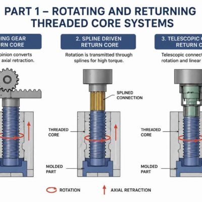
- Mechanism 8 – Manual Unscrewing Type 1
- Mechanism 9 – Manual Unscrewing Type 2
- Mechanism 10 – Manual Unscrewing Type 3
These mechanisms share a common principle:
Human input provides the rotational motion required to release the molded thread.
Why Manual Unscrewing Systems Still Exist
A common mistake among inexperienced mold designers is assuming that every threaded component requires automation.
This is often economically incorrect.
Consider the following example.
Annual Production
5,000 Parts
Product Life
3 Years
Total Production
15,000 Parts
Installing:
- Servo motors
- Hydraulic cylinders
- Gear trains
may increase mold cost by thousands of euros.
In many cases, the investment will never be recovered.
A manual system may produce the same parts at a fraction of the tooling cost.
What Is a Manual Unscrewing System?
A manual unscrewing system is a mechanism that requires operator intervention to release the molded thread.
The operator may:
- Rotate a handle
- Remove a threaded core
- Unscrew a core directly
The exact procedure depends on the mechanism design.
Unlike automatic systems, the cycle cannot be completed without operator involvement.
Advantages of Manual Systems
Manual unscrewing systems offer several significant advantages.
Low Tooling Cost
No:
- Motors
- Hydraulic cylinders
- Servo drives
- Complex controls
are required.
Simple Construction
Most manual systems contain relatively few moving parts.
This simplifies:
- Manufacturing
- Assembly
- Maintenance
High Reliability
Fewer components generally result in:
- Lower failure rates
- Reduced maintenance
Easy Repair
Most repairs can be performed using conventional machine shop tools.
Limitations of Manual Systems
Despite their advantages, manual systems are not suitable for every application.
Reduced Productivity
Manual intervention increases cycle time.
Operator Dependency
Performance depends on:
- Operator skill
- Operator consistency
Ergonomic Limitations
Repeated manual operation may create:
- Fatigue
- Repetitive motion concerns
Production Constraints
Manual systems are rarely suitable for:
- Fully automated production
- Extremely high production volumes
Mechanism 8 – Manual Unscrewing Type 1
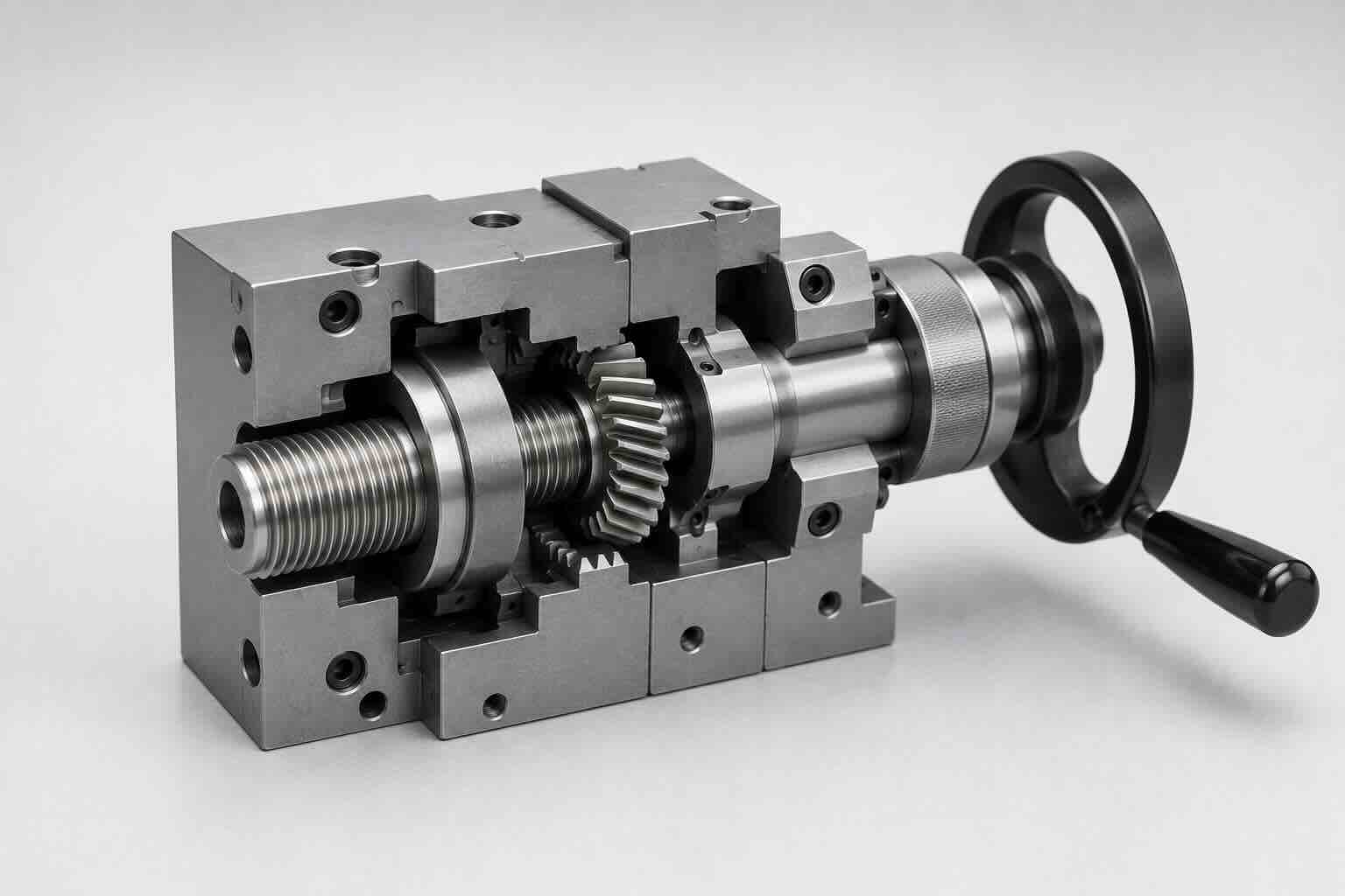
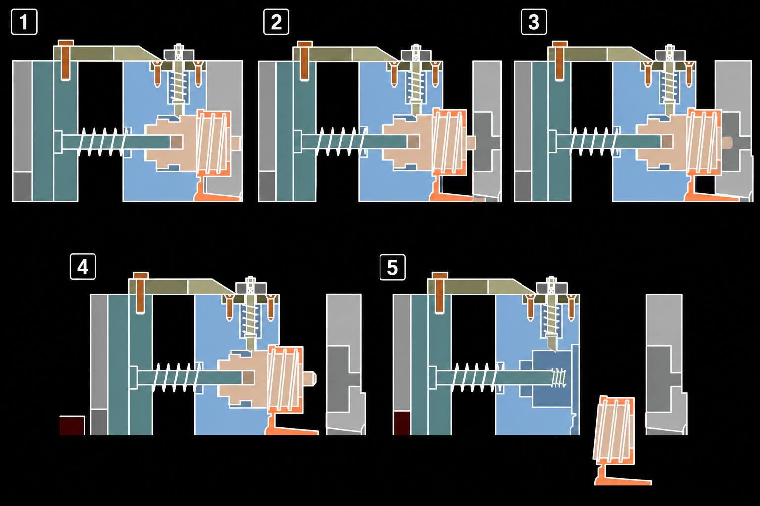
Mechanism 8 uses a manually operated handle connected to a bevel gear system.
The operator rotates the handle after mold opening.
The bevel gears transmit rotational movement to the threaded core.
A stripper plate supports the component during thread release.
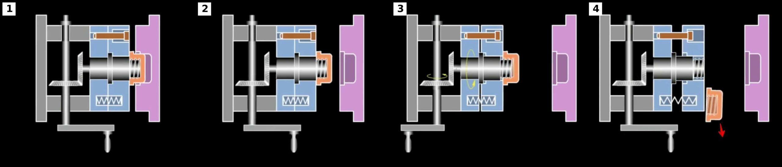
Operating Sequence
Step 1
Mold opens.
Step 2
Operator rotates handle.
Step 3
Bevel gears rotate threaded core.
Step 4
Thread disengages.
Step 5
Stripper plate supports part movement.
Step 6
Part is removed.
Advantages of Mechanism 8
- Low cost
- Simple design
- Good mechanical advantage
- Suitable for moderate thread sizes
Typical Applications
- Industrial prototypes
- Service parts
- Maintenance components
- Small production runs
Mechanism 9 – Manual Unscrewing Type 2
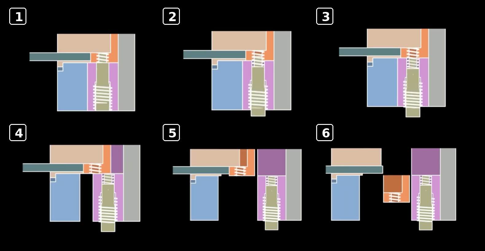
Mechanism 9 combines mechanical release with manual core removal.
Unlike Mechanism 8, the threaded core itself is removed from the molded component.
The mold contains:
- Wedge system
- Bayonet locking system
- Threaded core
The operator removes the core after mold opening.
Operating Sequence
Step 1
Mold opens.
Step 2
Ejector system moves.
Step 3
Bayonet locking system disengages.
Step 4
Threaded core becomes free.
Step 5
Operator removes threaded core.
Step 6
Part is separated from core.
Advantages of Mechanism 9
- Extremely simple construction
- Very low tooling cost
- Suitable for difficult thread geometries
Limitations
- Slower operation
- Additional handling required
- Increased operator involvement
Typical Applications
- Prototype tooling
- Laboratory molds
- Specialized industrial products
Mechanism 10 – Manual Unscrewing Type 3
Mechanism 10 is the simplest manual thread release method.
The threaded core remains inside the mold.
Before mold opening, the operator manually unscrews the core.
After mold closure, the operator screws the core back into position.
This design eliminates most transmission components.
Operating Sequence
Step 1
Molding cycle completes.
Step 2
Operator manually unscrews core.
Step 3
Mold opens.
Step 4
Part is removed.
Step 5
Operator re-installs threaded core.
Step 6
Next cycle begins.
Advantages of Mechanism 10
- Lowest tooling cost
- Minimal components
- Extremely simple design
Limitations
- Slowest cycle time
- Highest operator involvement
- Unsuitable for larger production volumes
Comparing the Three Manual Systems
| Parameter | Mechanism 8 | Mechanism 9 | Mechanism 10 |
|---|---|---|---|
| Tool Cost | Low | Very Low | Lowest |
| Productivity | Moderate | Low | Very Low |
| Complexity | Medium | Low | Very Low |
| Maintenance | Low | Very Low | Very Low |
| Reliability | Excellent | Excellent | Excellent |
When Should Manual Systems Be Selected?
Manual systems are often appropriate when:
Annual Production
Less than 50,000 Parts
Tool Budget
Limited
Automation Requirement
Low
Product Life
Short
Prototype Development
Required
Under these conditions, manual systems frequently provide the lowest total cost.
Economic Evaluation Example
Consider two alternatives.
Automatic Unscrewing Mold
Additional Cost
€15,000
Manual Unscrewing Mold
Additional Cost
€2,000
Difference
€13,000
For a product requiring only 10,000 parts over its lifetime, the automated solution may never recover its additional investment.
Design Parameters Required
Before designing a manual unscrewing system, the engineer must know:
□ Thread Diameter
□ Thread Pitch
□ Thread Engagement Length
□ Required Turns
□ Production Volume
□ Available Operator Access
□ Ergonomic Requirements
□ Cycle Time Targets
These values determine whether manual operation is practical.
Manual Unscrewing Design Checklist
Before selecting a manual system verify:
□ Production volume suitable
□ Operator access available
□ Ergonomics acceptable
□ Thread geometry reviewed
□ Maintenance requirements reviewed
□ Economic justification completed
Part 2 – Torque Calculations, Handle Design, Mechanical Advantage and Ergonomics
In Part 1, we examined the operating principles of the three manual unscrewing mechanisms:
- Mechanism 8 – Manual Unscrewing Type 1
- Mechanism 9 – Manual Unscrewing Type 2
- Mechanism 10 – Manual Unscrewing Type 3
The next step is determining whether an operator can practically release the thread.
Unlike hydraulic or motor-driven systems, manual systems rely entirely on human force.
The engineer must ensure that:
- Required torque is acceptable
- Handle force is reasonable
- Operator fatigue is minimized
- Cycle time remains practical
- Ergonomic limits are respected
These calculations are critical because a technically functional mold may still fail economically if the manual effort becomes excessive.
The Human Operator as a Power Source
Manual unscrewing systems use human energy.
This introduces engineering constraints that do not exist in automatic systems.
Human capability depends on:
- Strength
- Posture
- Repetition rate
- Fatigue
- Working environment
For this reason, manual systems require ergonomic evaluation.
Determining Required Unscrewing Torque
The starting point is calculating thread release torque.
Assume:
Thread Diameter = 38 mm
Material = Polypropylene
Required Unscrewing Torque = 8 Nm
This torque must ultimately be supplied by the operator.
Why Torque Matters
A thread requiring:
5 Nm
can be comfortably operated.
A thread requiring:
40 Nm
may become impractical for repetitive operation.
Torque is therefore the primary design parameter.
Safety Factors
Real-world conditions vary.
Factors include:
- Material shrinkage
- Mold temperature
- Contamination
- Wear
Recommended Safety Factors:
Prototype Mold
1.5
Production Mold
2.0
Difficult Materials
2.5
Example
Calculated Torque
8 Nm
Safety Factor
2
Calculation
Design Torque
8 × 2
Design Torque = 16 Nm
Result
The manual system should be capable of transmitting:
16 Nm
Basic Handle Force Calculation
The operator applies force through a handle.
Formula
Force = Torque / Radius
Where:
Force = N
Torque = Nm
Radius = m
Example
Required Torque
16 Nm
Handle Length
200 mm
Convert Radius
200 mm = 0.20 m
Calculation
Force = 16 / 0.20
Force = 80 N
Result
Operator Force = 80 N
Understanding Human Force
Approximate continuous operating forces:
One-Hand Operation
50 to 80 N
Comfortable Two-Hand Operation
100 to 150 N
Short-Duration Maximum Force
250 to 300 N
The goal is to remain within the comfortable range.
Effect of Handle Length
Increasing handle length reduces required force.
Example 1
Torque = 16 Nm
Handle = 150 mm
Force = 16 / 0.15
Force = 107 N
Example 2
Torque = 16 Nm
Handle = 300 mm
Force = 16 / 0.30
Force = 53 N
Result
Doubling handle length approximately halves operator force.
Mechanism 8 – Bevel Gear System
Mechanism 8 uses bevel gears to provide mechanical advantage.
The operator rotates a handle.
The bevel gear system transfers motion to the threaded core.
Gear Ratio Fundamentals
Formula
Gear Ratio =
Driven Gear Teeth
/
Driving Gear Teeth
Example
Driving Gear
20 Teeth
Driven Gear
60 Teeth
Calculation
Gear Ratio =
60 / 20
Gear Ratio = 3
Result
The operator gains:
3 Times More Torque
while losing rotational speed.
Torque Multiplication
Formula
Output Torque = Input Torque × Gear Ratio
Example
Operator Torque
8 Nm
Gear Ratio
3
Calculation
Output Torque =
8 × 3
Output Torque = 24 Nm
Result
Threaded Core Torque = 24 Nm
Mechanical Efficiency
Real gear systems are not perfect.
Typical Bevel Gear Efficiency
90 to 95 Percent
Example
Theoretical Torque
24 Nm
Efficiency
90 Percent
Calculation
Actual Torque
24 × 0.90
Actual Torque = 21.6 Nm
Result
Available Torque = 21.6 Nm
Number of Turns Required
Thread Geometry
Pitch = 3 mm
Engagement Length = 12 mm
Formula
Turns =
Engagement Length
/
Pitch
Calculation
Turns =
12 / 3
Turns = 4
Result
Required Thread Revolutions = 4
Operator Rotation Requirement
For a 3:1 Gear Ratio
Formula
Operator Turns =
Thread Turns × Gear Ratio
Calculation
Operator Turns =
4 × 3
Operator Turns = 12
Result
The operator rotates the handle:
12 Turns
to release the thread.
Why Gear Ratios Are a Trade-Off
Higher Gear Ratio
Advantages
- Lower force
Disadvantages
- More handle rotations
Lower Gear Ratio
Advantages
- Faster operation
Disadvantages
- Higher force
The designer must balance these factors.
Mechanism 9 Considerations
Mechanism 9 does not rely heavily on operator torque.
Instead:
The operator removes the threaded core.
Primary concerns become:
- Handling effort
- Accessibility
- Cycle time
Core Removal Force
Example
Core Weight
1.5 kg
Formula
Force = Mass × Gravity
Calculation
Force =
1.5 × 9.81
Force = 14.7 N
Result
Handling Force = 14.7 N
Usually acceptable.
Mechanism 10 Considerations
Mechanism 10 requires direct manual unscrewing.
The operator applies torque directly to the core.
No mechanical advantage may be available.
This often limits practical thread size.
Ergonomic Guidelines
For repetitive production environments:
Recommended Maximum Continuous Torque
10 Nm
Preferred Torque
5 Nm
or less
For occasional operation:
15 to 20 Nm
may be acceptable.
Operator Fatigue
Fatigue increases with:
- Torque
- Repetition rate
- Awkward posture
- Handle size
The mold should be designed to minimize all four factors.
Handle Design
A poor handle design can double operator fatigue.
Recommended Handle Diameter
25 to 40 mm
Recommended Grip Length
100 to 150 mm
Recommended Surface
Textured
Non-slip
Cycle Time Analysis
Consider:
Unscrewing Time
5 Seconds
Handling Time
3 Seconds
Core Reinstallation
4 Seconds
Total Manual Time
12 Seconds
For low-volume production this may be acceptable.
For mass production it becomes problematic.
Engineering Example
Product
Threaded Prototype Housing
Thread Diameter
30 mm
Pitch
2 mm
Engagement
10 mm
Required Torque
6 Nm
Safety Factor
2
Design Torque
12 Nm
Handle Length
250 mm
Operator Force
12 / 0.25
Operator Force = 48 N
Result
Comfortable Manual Operation
Suitable for Mechanism 8
Common Design Mistakes
Mistake 1
Ignoring operator fatigue.
Mistake 2
Using excessively short handles.
Mistake 3
Selecting unnecessary gear ratios.
Mistake 4
Ignoring cycle time.
Mistake 5
Poor ergonomic positioning.
Design Checklist
Before approving a manual unscrewing system verify:
□ Required torque calculated
□ Safety factor applied
□ Handle force calculated
□ Gear ratio selected
□ Number of operator turns calculated
□ Ergonomic limits reviewed
□ Handle dimensions verified
□ Cycle time evaluated
□ Operator accessibility verified
□ Fatigue considered
Part 3 – Shaft Design, Bevel Gears, Bearings, Wear and Reliability
In Part 2, we calculated:
- Required unscrewing torque
- Handle force
- Mechanical advantage
- Gear ratios
- Operator effort
- Ergonomic limits
These calculations determine whether a manual system is practical.
However, practical operation alone does not guarantee a successful mold.
The mechanical components must also survive:
- Thousands of cycles
- Operator misuse
- Shock loads
- Wear
- Long-term service
This chapter focuses on the mechanical components that determine reliability.
We will examine:
- Shaft design
- Bevel gear sizing
- Key design
- Bearing selection
- Wear mechanisms
- Reliability engineering
These factors are particularly important for Mechanism 8, but also affect Mechanisms 9 and 10.
Why Mechanical Reliability Matters
Many designers assume manual molds experience low stress.
This is often incorrect.
Human operators create:
- Shock loads
- Inconsistent torque
- Sudden reversals
- Excessive force
A poorly designed manual mechanism may fail much sooner than expected.
Components Subject to Wear
Mechanism 8 contains:
- Handle
- Shaft
- Bevel gears
- Keys
- Bearings
Each component must be designed appropriately.
Shaft Design Fundamentals
The shaft transfers operator torque to the threaded core.
The shaft experiences:
- Torsional loading
- Bending loads
- Fatigue loading
The first design step is verifying torsional stress.
Torsional Stress Formula
Formula
Shear Stress =
16 × Torque
/
(3.1416 × Diameter³)
Where:
Torque = Nmm
Diameter = mm
Stress = MPa
Example
Design Torque
20 Nm
Convert
20 Nm = 20,000 Nmm
Assume
Diameter = 16 mm
Calculation
Shear Stress =
(16 × 20,000)
/
(3.1416 × 16³)
Shear Stress = 24.9 MPa
Result
Acceptable for common tool steels.
Shaft Diameter Estimation
The equation may be rearranged.
Formula
Diameter = Cube Root Of
(16 × Torque)
/
(3.1416 × Allowable Stress)
Example
Torque = 20,000 Nmm
Allowable Stress = 60 MPa
Calculation
Diameter ≈ 12 mm
Engineering Practice
Select:
16 mm
to improve stiffness and reliability.
Why Stiffness Matters
A shaft may be strong enough but still be too flexible.
Excessive deflection creates:
- Gear misalignment
- Uneven wear
- Rough operation
In manual systems, stiffness is often more important than strength.
Bevel Gear Fundamentals
Mechanism 8 commonly uses bevel gears.
Bevel gears transfer motion between intersecting shafts.
Most manual systems use:
90 Degree Shaft Arrangement
because it improves operator accessibility.
Why Bevel Gears Are Used
Advantages
- Compact layout
- Good mechanical efficiency
- Simple operation
Bevel Gear Efficiency
Typical Efficiency
90 to 95 Percent
Example
Input Torque
20 Nm
Efficiency
92 Percent
Calculation
Output Torque
20 × 0.92
Output Torque = 18.4 Nm
Result
Available Core Torque = 18.4 Nm
Gear Tooth Force
Gear teeth must transmit torque.
Formula
Force = Torque / Radius
Example
Output Torque
18.4 Nm
Gear Radius
20 mm
Radius = 0.02 m
Calculation
Force =
18.4 / 0.02
Force = 920 N
Result
Tooth Force = 920 N
Gear Material Selection
Common materials:
Hardened Tool Steel
Advantages
- Excellent wear resistance
- Long service life
Recommended for production molds.
Alloy Steel
Advantages
- Good toughness
- Lower cost
Common choice.
Bronze
Occasionally used to reduce friction.
Suitable for light-duty applications.
Key Design
Keys transmit torque between:
- Shaft
- Gear
Improper key design is a common source of failure.
Key Force Calculation
Formula
Force = Torque / Radius
Example
Torque = 18.4 Nm
Radius = 8 mm
Radius = 0.008 m
Calculation
Force =
18.4 / 0.008
Force = 2300 N
Result
Key Force = 2300 N
Recommended Key Sizes
Typical Shaft
16 mm
Recommended Key
5 × 5 mm
Length
25 to 35 mm
This provides adequate torque capacity for most manual systems.
Bearing Selection
Bearings support rotating shafts.
Even manual molds benefit from proper bearing design.
Common Bearing Types
Deep Groove Ball Bearings
Advantages
- Low friction
- Low cost
- Easy replacement
Most common choice.
Needle Bearings
Advantages
- Compact
- High load capacity
Suitable for limited space.
Bronze Bushings
Advantages
- Simple
- Low cost
Often used in prototype molds.
Bearing Load Example
Gear Force
920 N
Assume:
Bearing Load
920 N
This load is used to select bearing size.
Mechanism 9 Reliability
Mechanism 9 contains very few moving parts.
Primary wear areas:
- Bayonet lock
- Guide surfaces
- Core interface
Advantages
- Extremely high reliability
- Low maintenance
Mechanism 10 Reliability
Mechanism 10 is mechanically the simplest system.
Primary wear areas:
- Threaded core
- Operator handling surfaces
Advantages
- Minimal component count
- Very low maintenance
Wear Mechanisms
The most common wear sources are:
Abrasive Wear
Caused by:
- Dirt
- Glass-filled materials
- Contamination
Adhesive Wear
Caused by:
- Poor lubrication
- Metal-to-metal contact
Impact Wear
Caused by:
- Sudden operator loading
- Rough handling
Lubrication
Even manual systems benefit from proper lubrication.
Recommended Areas
- Bevel gears
- Bearings
- Sliding surfaces
Benefits
- Lower wear
- Reduced operating force
- Longer service life
Reliability Engineering
A reliable manual mold should survive:
- Prototype production
- Service part production
- Small batch production
with minimal maintenance.
Typical Reliability Targets
Prototype Mold
100,000 Cycles
Production Service Mold
500,000 Cycles
Industrial Spare Part Mold
1 Million Cycles
These values are usually achievable with proper design.
Engineering Example
Thread Diameter
40 mm
Required Torque
12 Nm
Handle Force
50 N
Shaft Diameter
16 mm
Gear Ratio
2:1
Bevel Gear Efficiency
92 Percent
Available Output Torque
22.1 Nm
Result
Suitable for long-term manual operation.
Common Design Mistakes
Mistake 1
Undersized shafts.
Mistake 2
Ignoring gear efficiency.
Mistake 3
Using soft gear materials.
Mistake 4
Poor lubrication.
Mistake 5
Ignoring operator misuse.
Design Checklist
Before approving a manual system verify:
□ Shaft stress calculated
□ Shaft diameter verified
□ Gear forces calculated
□ Bevel gear selected
□ Key dimensions verified
□ Bearing loads calculated
□ Lubrication specified
□ Wear reviewed
□ Reliability target established
□ Maintenance access verified
Part 4 – Complete Design Example, Cost Analysis, Optimization and Best Practices
In Parts 1, 2 and 3, we developed the engineering foundation required to design manual unscrewing systems.
We examined:
- Mechanism 8 – Manual Unscrewing Type 1
- Mechanism 9 – Manual Unscrewing Type 2
- Mechanism 10 – Manual Unscrewing Type 3
- Torque calculations
- Handle force calculations
- Mechanical advantage
- Ergonomic considerations
- Shaft design
- Bevel gear sizing
- Bearing selection
- Reliability engineering
The final step is integrating these calculations into a complete design methodology.
This chapter demonstrates how experienced mold designers evaluate manual systems, optimize performance and determine when manual operation remains the most economical solution.
Complete Design Example
We will design a manual unscrewing system for a prototype industrial component.
Product Data
Part Description
Threaded Electrical Housing
Material
Glass Filled Nylon
Thread Diameter
40 mm
Thread Pitch
2.5 mm
Thread Engagement Length
10 mm
Annual Production
15,000 Parts
Expected Mold Life
5 Years
Target Reliability
95 Percent
Step 1 – Calculate Required Turns
Formula
Number of Turns =
Engagement Length
/
Pitch
Calculation
Turns =
10 / 2.5
Turns = 4
Result
Required Turns = 4
Step 2 – Estimate Unscrewing Torque
Based on:
- Material shrinkage
- Thread geometry
- Glass fiber reinforcement
Estimated Torque
10 Nm
Apply Safety Factor
2
Formula
Design Torque =
10 × 2
Design Torque = 20 Nm
Result
Required Design Torque = 20 Nm
Step 3 – Select Mechanism
Possible Choices
Mechanism 8
Manual Bevel Gear System
Mechanism 9
Removable Core System
Mechanism 10
Direct Manual Core Removal
Engineering Evaluation
Production Volume
15,000 Parts Per Year
Automation Requirement
Low
Budget
Limited
Result
Mechanism 8 Selected
Reason
Provides a good balance between productivity and tooling cost.
Step 4 – Determine Handle Length
Target Operator Force
Less Than 80 N
Formula
Force = Torque / Radius
Rearranged
Radius = Torque / Force
Calculation
Radius =
20 / 80
Radius = 0.25 m
Result
Required Handle Length
250 mm
Step 5 – Verify Operator Force
Formula
Force = Torque / Radius
Calculation
Force =
20 / 0.25
Force = 80 N
Result
Acceptable
Comfortable for regular operation.
Step 6 – Select Gear Ratio
Chosen Gear Ratio
2:1
Advantages
- Reduced operating force
- Moderate handle rotation
Step 7 – Calculate Operator Rotations
Required Thread Rotations
4
Gear Ratio
2
Formula
Operator Turns =
4 × 2
Operator Turns = 8
Result
Operator Rotates Handle
8 Turns
to fully release the thread.
Step 8 – Verify Output Torque
Operator Torque
20 Nm
Gear Ratio
2
Efficiency
92 Percent
Formula
Output Torque =
20 × 2 × 0.92
Output Torque = 36.8 Nm
Result
Available Torque = 36.8 Nm
Large safety margin exists.
Step 9 – Shaft Design
Selected Shaft Diameter
16 mm
From Part 3:
Calculated Stress
24.9 MPa
Result
Acceptable
Excellent long-term durability.
Step 10 – Bearing Selection
Bearing Type
Deep Groove Ball Bearing
Advantages
- Low friction
- Low cost
- Easy replacement
Recommended for Mechanism 8.
Step 11 – Reliability Review
Expected Production
15,000 × 5
Total Production
75,000 Parts
This production level is easily achievable with a properly designed manual system.
Why Mechanism 8 Was Selected
Mechanism 8 provides:
- Faster operation
- Better ergonomics
- Lower fatigue
- Improved productivity
compared with Mechanisms 9 and 10.
For this application, it offers the best overall solution.
When Mechanism 9 Is Better
Mechanism 9 is often preferable when:
- Production volume is extremely low
- Thread geometry is difficult
- Tool budget is very limited
Typical examples include:
- Prototype molds
- Research molds
- Laboratory tooling
When Mechanism 10 Is Better
Mechanism 10 is appropriate when:
- Production quantities are very small
- Mold simplicity is critical
- Operator access is excellent
It often represents the lowest-cost solution available.
Cost Analysis
One of the primary advantages of manual systems is reduced tooling cost.
Mechanism 8
Relative Cost
100 Percent
Baseline
Mechanical Automatic System
Relative Cost
180 to 250 Percent
Hydraulic System
Relative Cost
220 to 300 Percent
Servo Driven System
Relative Cost
250 to 400 Percent
For low-volume production, manual systems frequently provide the best economic return.
Production Volume Analysis
Manual systems become less attractive as production volume increases.
Very Low Volume
Less Than 10,000 Parts Per Year
Manual Systems
Excellent Choice
Low Volume
10,000 to 50,000 Parts Per Year
Manual Systems
Often Justified
Medium Volume
50,000 to 250,000 Parts Per Year
Economic Evaluation Required
High Volume
More Than 250,000 Parts Per Year
Automatic Systems Usually Preferred
Life-Cycle Cost Analysis
Tooling cost alone does not determine profitability.
The correct calculation is:
Total Cost =
Tool Cost
Operating Cost
Maintenance Cost
Labor Cost
Example
Manual Mold
Tool Cost
€15,000
Maintenance
€2,000
Labor
€8,000
Total
€25,000
Automatic Mold
Tool Cost
€35,000
Maintenance
€4,000
Labor
€500
Total
€39,500
Result
Manual System Saves
€14,500
for this production scenario.
Design Optimization Strategies
Experienced mold designers apply several optimization methods.
Strategy 1
Minimize Required Torque
Methods:
- Polished cores
- Improved cooling
- Better thread geometry
Strategy 2
Increase Handle Length
Benefits:
- Lower operator force
- Reduced fatigue
Strategy 3
Optimize Gear Ratio
Balance:
- Force
- Number of handle rotations
Strategy 4
Reduce Core Weight
Benefits:
- Easier handling
- Faster operation
Strategy 5
Improve Accessibility
Benefits:
- Reduced cycle time
- Better ergonomics
Preventive Maintenance Schedule
Even manual molds benefit from maintenance planning.
Every 50,000 Cycles
Inspect:
- Bevel gears
- Keys
- Fasteners
Every 100,000 Cycles
Inspect:
- Bearings
- Shaft wear
- Lubrication
Every 250,000 Cycles
Major inspection
Verify:
- Alignment
- Gear wear
- Core condition
Common Design Mistakes
Mistake 1
Ignoring operator fatigue.
Mistake 2
Using excessive gear reduction.
Mistake 3
Poor handle positioning.
Mistake 4
Underestimating labor costs.
Mistake 5
Selecting manual systems for high-volume production.
Best Engineering Practices
Best Practice 1
Calculate operating torque before selecting a mechanism.
Best Practice 2
Maintain operator force below 80 N whenever possible.
Best Practice 3
Optimize gear ratios carefully.
Best Practice 4
Design for maintenance access.
Best Practice 5
Evaluate labor costs realistically.
Best Practice 6
Consider total ownership cost.
Best Practice 7
Use the simplest mechanism capable of meeting requirements.
Manual Unscrewing Design Workflow
Step 1
Determine production volume.
Step 2
Calculate required torque.
Step 3
Calculate handle force.
Step 4
Evaluate ergonomics.
Step 5
Select mechanism.
Step 6
Design gears and shafts.
Step 7
Verify reliability.
Step 8
Perform economic analysis.
Step 9
Optimize operation.
Step 10
Finalize design.
Final Design Checklist
Before releasing a manual unscrewing mold verify:
□ Production volume evaluated
□ Torque calculated
□ Handle force verified
□ Ergonomics reviewed
□ Gear ratio selected
□ Shaft verified
□ Bearings selected
□ Reliability target established
□ Maintenance access reviewed
□ Labor cost evaluated
□ Life-cycle cost analyzed
□ Mechanism selection justified
Conclusion
Manual unscrewing systems remain highly valuable in modern mold design.
While they cannot compete with automated systems in high-volume production, they often provide the lowest total ownership cost for:
- Prototype molds
- Service part molds
- Research tooling
- Low-volume industrial products
The three mechanisms discussed throughout this article offer different balances between:
- Cost
- Productivity
- Complexity
- Reliability
By applying the engineering calculations and design methodologies presented in this guide, mold designers can confidently determine when manual unscrewing remains the optimal solution.