Introduction
Hydraulic cylinders used in injection molds are designed to withstand extremely demanding operating conditions. Modern cylinders are engineered with generous safety factors, carefully selected materials, and rigorous testing to ensure reliable performance over millions of operating cycles.
Yet, on rare occasions, a cylinder tube deforms permanently, leading many users to immediately conclude that the cylinder itself has failed.
In reality, permanent deformation of a hydraulic cylinder tube is almost never caused by normal operating pressure.
Instead, it is often the consequence of an abnormal event that generates an internal pressure far higher than the nominal hydraulic pressure supplied by the machine.
A real engineering investigation conducted by the Vega Technical Department perfectly illustrates this phenomenon. Four hydraulic cylinders installed on the ejector plate of an injection mold suffered identical tube deformation. Rather than assuming a manufacturing defect, Vega applied a systematic engineering investigation to determine the true root cause.
This case demonstrates one of the most important principles of hydraulic engineering:
Hydraulic cylinders rarely fail without a cause. Most failures are the consequence of abnormal operating conditions rather than defective components.
The Failure
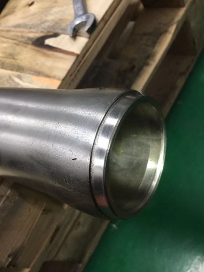
A customer reported that four identical hydraulic cylinders, model CR063045G0GGGM350, had experienced severe deformation of the cylinder tube during production. According to the initial information, all four cylinders showed the same damage, suggesting that the problem was systemic rather than an isolated manufacturing defect.
From an engineering perspective, this immediately raised an important question.
If every cylinder failed in exactly the same way, could the cylinders really be responsible?
Or was another component of the system generating abnormal loads?
This distinction is fundamental in every Root Cause Analysis.
The First Step: Verify the Design Limits
Before investigating the mold, Stefano Rogora reviewed the design specifications of the cylinder.
The tube was manufactured from AISI 304 stainless steel, selected for its mechanical strength and corrosion resistance.
According to Vega’s engineering calculations:
- Maximum catalog working pressure: 215 bar
- Static burst resistance: approximately 448 bar
- Fatigue pressure limit: approximately 315 bar
These values immediately revealed an important fact.
The cylinder had a substantial safety margin above its nominal operating pressure.
Therefore, under normal operating conditions, deformation of the tube should not occur.
The investigation had to focus elsewhere.
Possible Causes
Rather than immediately blaming the hydraulic cylinder, the Vega Technical Department identified three possible scenarios:
1. High-speed movement combined with the inertia of the moving mass
Rapid deceleration of heavy moving components can generate transient hydraulic pressure spikes.
2. Incorrect mold closing sequence
The mold may have closed while the cylinders were still fully extended and hydraulically pressurized.
3. Hydraulic valve malfunction
A defective directional valve or hydraulic control valve could potentially generate abnormal pressure peaks within the cylinder.
At this stage, no conclusions were drawn.
Every hypothesis had to be verified.
Looking Beyond the Cylinder
After reviewing the mold drawings, Stefano noticed an important design feature.
The four hydraulic cylinders were connected to the ejector plate, while their rods were linked to the fixed mold structure through floating joints.
This arrangement suggested a possible failure mechanism.
If the injection molding machine began closing the mold while the ejector cylinders remained extended and pressurized, the enormous clamping force of the machine could mechanically push the ejector plate backwards.
Since hydraulic oil trapped inside a closed cylinder is practically incompressible, reducing its internal volume would produce a dramatic increase in pressure.
The cylinder itself would no longer be driven by the hydraulic power unit.
Instead, it would behave like a closed pressure vessel subjected to external mechanical compression.
Pressure Intensification
This phenomenon is known as pressure intensification.
Unlike normal hydraulic pressure generated by the pump, pressure intensification occurs when an external mechanical force compresses oil trapped inside a closed hydraulic chamber.
Because hydraulic oil is only minimally compressible, even a very small reduction in internal volume may produce an extremely high pressure increase.
The hydraulic power unit may still be operating at 160 or 180 bar.
Inside the trapped cylinder, however, pressure may rise well beyond the nominal system pressure.
If this pressure exceeds the elastic limit of the cylinder tube, permanent deformation becomes inevitable.
This explains why hydraulic failures of this type are frequently associated with incorrect machine sequences rather than defective cylinders.
Why All Four Cylinders Failed
Initially, Stefano believed only one cylinder had been damaged.
However, after receiving additional photographs, it became clear that all four cylinders exhibited identical deformation.
This observation significantly strengthened the pressure intensification hypothesis.
A manufacturing defect affecting four identical cylinders simultaneously would be extremely unlikely.
Conversely, an incorrect mold closing sequence would expose every cylinder to exactly the same abnormal loading condition.
The failure pattern itself became one of the strongest pieces of engineering evidence.
Engineering Is the Process of Eliminating Possibilities
One of the most valuable aspects of this case is the engineering methodology adopted by the Vega Technical Department.
Rather than immediately replacing damaged components, Stefano systematically eliminated potential causes.
He requested:
- the customer’s hydraulic working pressure;
- confirmation of how many cylinders were damaged;
- photographs of the installation;
- verification of the mold operating sequence.
Only after gathering sufficient evidence did the investigation converge toward the most probable explanation.
This is the essence of professional Failure Analysis.
How to Prevent Pressure Intensification
Although pressure intensification cannot always be eliminated completely, proper mold design can significantly reduce the risk.
Recommended engineering practices include:
- ensuring that cylinders are fully retracted before mold closing;
- implementing reliable safety interlocks;
- verifying machine sequencing during commissioning;
- avoiding trapped hydraulic chambers whenever possible;
- installing appropriate pressure relief devices when required;
- regularly inspecting hydraulic valves and sensors.
Most importantly, mold movement should never rely solely on software logic without mechanical confirmation of cylinder position.
Lessons Learned
This engineering case provides several important lessons.
- Hydraulic cylinder deformation is rarely caused by normal operating pressure.
- Simultaneous failure of multiple cylinders usually indicates a system-level problem.
- Pressure intensification can generate internal pressures far higher than pump pressure.
- Hydraulic oil behaves almost as an incompressible fluid under operating conditions.
- Root Cause Analysis requires investigation before component replacement.
- Correct mold sequencing is essential for hydraulic system reliability.
Conclusion
Permanent deformation of a hydraulic cylinder tube is one of the most serious failures that can occur in an injection mold.
However, as this real Vega Technical Department case demonstrates, the cylinder is often only the visible victim of a much larger system problem.
By analyzing material properties, pressure limits, mold kinematics, and machine operating sequences, Vega identified the most probable root cause without immediately blaming the hydraulic component.
This engineering approach transforms a simple warranty claim into a valuable lesson in hydraulic system design.
Ultimately, the most reliable hydraulic cylinder is not simply the strongest one.
It is the one operating within a correctly designed and correctly controlled hydraulic system.