Introduction
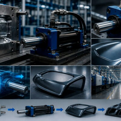
In injection molds, die-casting dies, and many industrial automation systems, it is common to move two, four, or even more hydraulic cylinders simultaneously. At first glance, the solution appears simple: connect all cylinders to the same hydraulic line and operate them together.
In reality, this approach rarely produces synchronized movement.
Even cylinders with identical dimensions can move at different speeds due to manufacturing tolerances, friction, load variations, internal leakage, hose lengths, or pressure differences. A small synchronization error repeated over thousands of production cycles can cause premature wear, uneven loading, dimensional inaccuracies, and, in severe cases, damage to the mold itself.
For this reason, hydraulic engineers often use flow dividers, mechanical devices specifically designed to distribute hydraulic flow accurately between multiple actuators. However, selecting the correct flow divider is far more complex than simply deciding how many cylinders must be synchronized.
A real engineering case handled by the Vega Technical Department clearly demonstrates that choosing a flow divider without knowing the hydraulic characteristics of the system is impossible. Before recommending any component, Vega requested information such as operating pressure, pump flow rate, number of cylinders, cylinder dimensions, and required movement time. Without these parameters, any selection would simply be a guess.
Why Hydraulic Cylinders Do Not Move Exactly Together
Many engineers assume that identical cylinders connected in parallel will automatically move at the same speed.
Hydraulic systems do not behave this way.
Each cylinder may experience slightly different loads, friction coefficients, seal drag, hose pressure losses, or manufacturing tolerances. These small differences cause unequal oil distribution, producing different piston speeds.
During mold opening or closing, these differences may create:
- uneven movement;
- mechanical stresses;
- guide wear;
- misalignment;
- increased maintenance costs.
Synchronization therefore becomes an engineering necessity rather than a luxury.
What Is a Hydraulic Flow Divider?
A hydraulic flow divider is a mechanical device composed of two or more gear sections mechanically connected by a common shaft.
Unlike conventional flow control valves that divide oil through calibrated orifices, a gear-type flow divider mechanically forces every section to rotate at exactly the same speed.
Because each gear section has a precisely defined displacement, every outlet delivers a proportional amount of oil regardless of moderate pressure differences between the circuits. This design provides excellent synchronization with very low energy losses compared with traditional static flow dividers.
How Does It Work?
Pressurized oil enters the common inlet of the flow divider.
Inside the housing, the oil drives several gear elements connected by a shared shaft. Since all gears rotate together, each section transfers a fixed volume of oil during every revolution.
If all sections have identical displacement, each hydraulic cylinder receives exactly the same flow.
If different gear sizes are installed, the divider distributes different flow rates according to the displacement of each section, allowing cylinders with different sizes or different speed requirements to operate simultaneously.
Why Pressure and Flow Rate Are Essential
One of the most interesting aspects of the Vega case is that the customer initially requested a flow divider without providing any hydraulic data.
Stefano Rogora immediately explained that this information was insufficient.
Before selecting the divider, the following data were required:
- operating pressure;
- pump flow rate;
- number of cylinders;
- cylinder bore and stroke;
- required movement time.
Without these values, the displacement of each divider section cannot be calculated correctly.
This is one of the most common mistakes made when specifying hydraulic synchronization systems.
The Relationship Between Flow and Cylinder Speed
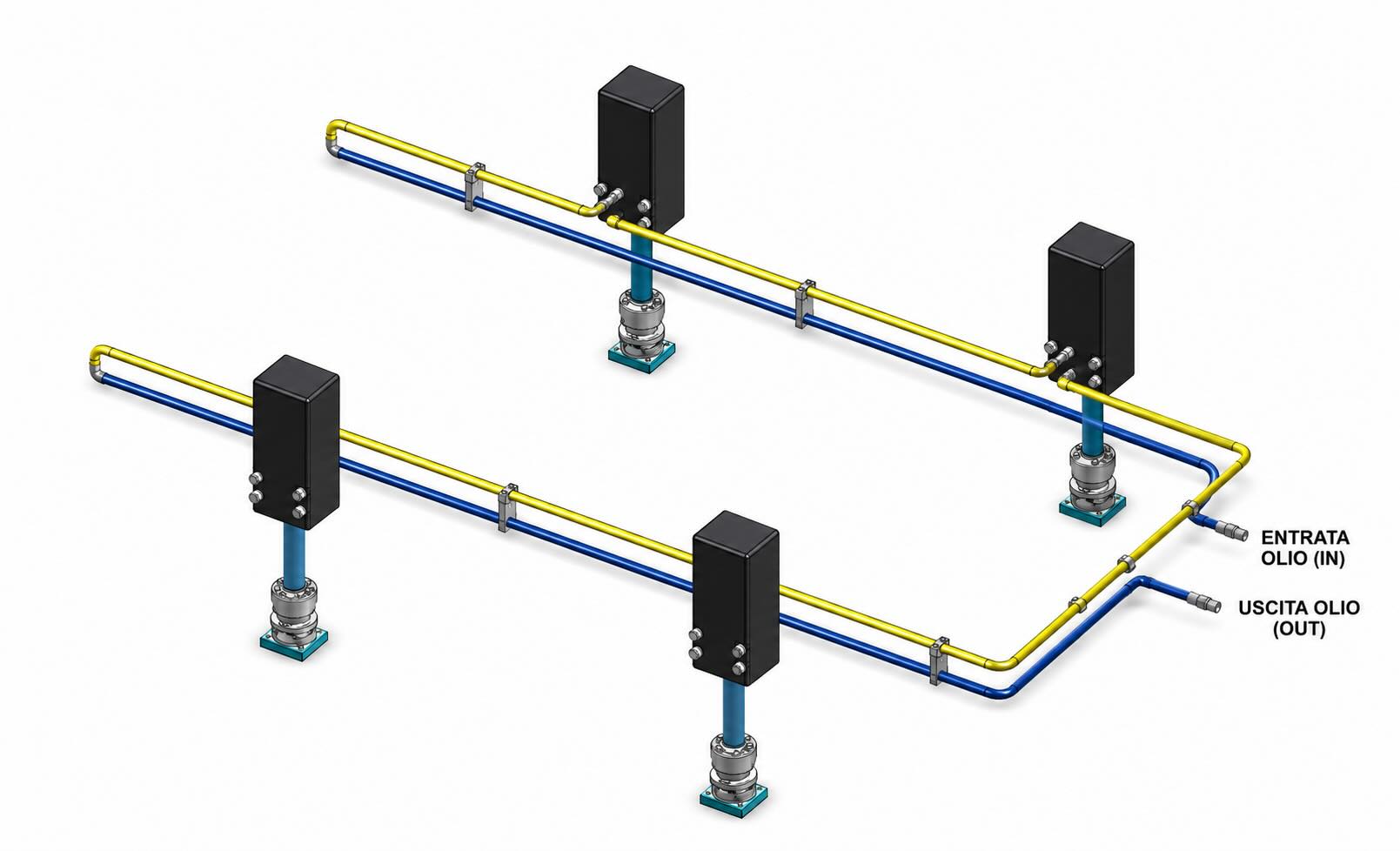
According to the Vega Technical Manual, piston speed depends directly on hydraulic flow rate.
A larger flow increases cylinder speed, while a lower flow reduces it. Cylinder diameter also plays a fundamental role because larger piston areas require greater oil volumes to achieve the same speed.
For example:
Four cylinders with a piston diameter of 50 mm and a stroke of 100 mm require approximately 196 cm³ of oil each.
If all four cylinders must complete the stroke in two seconds, the total required flow exceeds 23 litres per minute.
Only after calculating this value can the correct flow divider displacement be selected.
Phase Correction Valves
Some flow dividers are equipped with phase correction valves.
These valves automatically compensate for small synchronization errors that may accumulate during repeated operating cycles.
Instead of allowing cylinders to drift progressively out of synchronization, the valves restore equal positioning whenever pressure conditions permit. This feature is particularly important in injection molds where even a few millimeters of position error may produce excessive mechanical stresses.
Installation Is Equally Important
Selecting the correct divider is only part of the engineering work.
The Vega Technical Manual emphasizes that hydraulic performance also depends on:
- proper oil filtration;
- elimination of air inside the circuit;
- correct oil velocity;
- suitable hose dimensions;
- accurate cylinder alignment.
Air bubbles increase compressibility, contamination accelerates wear, and excessive oil velocity generates pressure losses that directly affect synchronization.
Even the best flow divider cannot compensate for poor hydraulic circuit design.
Lessons Learned from the Vega Case
The real engineering case demonstrates several important principles.
A flow divider cannot be selected based only on the number of cylinders.
Instead, engineers must understand the complete hydraulic system.
Correct synchronization depends on:
- pressure;
- pump flow;
- cylinder dimensions;
- operating cycle;
- hydraulic circuit layout;
- installation quality.
Only after evaluating all these parameters can a reliable synchronization system be designed.
Conclusion
Flow dividers are often considered simple hydraulic accessories.
In reality, they are precision mechanical devices that determine whether multiple hydraulic cylinders move as a perfectly synchronized system or as independent actuators fighting against each other.
The Vega Technical Department’s approach demonstrates that successful hydraulic engineering never begins by choosing a component.
It begins by understanding the application.
Only after analyzing pressure, flow rate, cylinder characteristics, operating cycle, and installation conditions can the correct flow divider be selected.
Ultimately, synchronization is not achieved by chance—it is achieved through engineering.