Fundamentals and Mechanism Selection
Thread unscrewing systems represent one of the most sophisticated areas of injection mold engineering. While simple molded components can be ejected directly from the mold using ejector pins, threaded parts create a mechanical lock between the molded plastic and the mold core.
This mechanical lock prevents conventional ejection and requires a dedicated release mechanism. The chosen release method has a direct influence on mold cost, cycle time, reliability, maintenance requirements, manufacturing complexity, and long-term profitability.
A mold designer who understands thread unscrewing systems can significantly reduce mold development risk while improving production efficiency.
This article introduces the engineering principles behind thread unscrewing systems and presents ten common mechanisms used throughout the injection molding industry.
Why Threaded Parts Are Difficult to Mold
The fundamental challenge of molding a threaded component is that the thread itself acts as an undercut.
When molten plastic is injected around a threaded core, the material cools and shrinks around the thread profile. The resulting component becomes mechanically trapped on the core.
Unlike a straight cylindrical surface, a thread cannot move axially without first disengaging from the helical profile.
The mold designer must therefore create a system capable of:
- Rotating the threaded core
- Collapsing the threaded core
- Elastically deforming the plastic thread
- Allowing manual removal
Each solution has advantages and limitations.
The correct solution depends on:
- Production volume
- Plastic material
- Thread geometry
- Required cycle time
- Available mold space
- Project budget
Internal Threads Versus External Threads
Before selecting a thread unscrewing system, the designer must determine whether the molded component contains internal or external threads.
External Threads
External threads are located on the outside diameter of the molded part.
Typical examples include:
- Bottle caps
- Closure systems
- Medical caps
- Protective covers
External threads are generally easier to mold and may sometimes be force stripped when flexible materials are used.
Internal Threads
Internal threads are located inside the molded component.
Typical examples include:
- Pipe fittings
- Fluid connectors
- Reservoir caps
- Electrical housings
Internal threads typically require more sophisticated mechanisms because the core becomes trapped inside the component.
In many cases, mechanical or hydraulic unscrewing systems become necessary.
The Four Engineering Challenges of Thread Unscrewing Systems
Every thread unscrewing mechanism must solve four fundamental engineering problems.
Challenge 1 – Thread Release
The thread must be disengaged without damaging the component.
Factors influencing thread release include:
- Thread pitch
- Thread depth
- Engagement length
- Plastic shrinkage
- Surface finish
Even small design changes can dramatically affect release forces.
Challenge 2 – Torque Generation
The mechanism must generate sufficient torque to overcome:
- Friction
- Shrinkage forces
- Material deformation
- Contamination
- Wear
Insufficient torque results in incomplete thread release.
Excessive torque increases wear and maintenance costs.
Challenge 3 – Cycle Time
Every unscrewing operation adds time to the molding cycle.
Example:
Molding Time = 8 seconds
Unscrewing Time = 2 seconds
Total Cycle Time = Molding Time + Unscrewing Time
Total Cycle Time = 8 + 2
Total Cycle Time = 10 seconds
A seemingly minor increase in unscrewing time can reduce annual production by hundreds of thousands of parts.
Challenge 4 – Reliability
Many threaded molds operate continuously for years.
Example:
Cycle Time = 10 seconds
Cycles Per Hour = 3600 / 10
Cycles Per Hour = 360
Cycles Per Day = 360 × 24
Cycles Per Day = 8,640
Cycles Per Year = 8,640 × 365
Cycles Per Year = 3,153,600
A mold operating for five years may exceed 15 million unscrewing cycles.
Reliability therefore becomes a critical design consideration.
Classification of the Ten Unscrewing Mechanisms
The ten mechanisms discussed in this guide can be grouped into five engineering families.
Family 1 – Motor Driven Systems
Mechanism Included:
- Mechanism 1
These systems use a motor and gear train to rotate the threaded core.
Advantages:
- Fully automatic
- Excellent repeatability
- Suitable for deep threads
Limitations:
- Higher mold cost
- Increased complexity
- More maintenance components
Family 2 – Rack and Pinion Systems
Mechanisms Included:
- Mechanism 2
- Mechanism 5
These systems convert linear motion into rotational motion.
Advantages:
- Compact
- Mechanically efficient
- No electric motor required
Limitations:
- Large rack travel may be required
- Gear wear must be considered
Family 3 – Hydraulic Systems
Mechanisms Included:
- Mechanism 3
- Mechanism 7
Hydraulic systems use cylinders to generate force and motion.
Advantages:
- High force capability
- Suitable for large threads
- Excellent control
Limitations:
- Hydraulic plumbing required
- Potential leakage risk
Family 4 – Force Stripping Systems
Mechanism Included:
- Mechanism 4
Force stripping relies on elastic deformation of the molded thread.
Advantages:
- Lowest mold cost
- Fastest cycle time
- Minimal moving parts
Limitations:
- Material dependent
- Limited thread geometry
Family 5 – Manual Systems
Mechanisms Included:
- Mechanism 8
- Mechanism 9
- Mechanism 10
These systems require operator intervention.
Advantages:
- Lowest tooling cost
- Simple construction
Limitations:
- Low productivity
- Operator dependent
Overview of the Ten Mechanisms
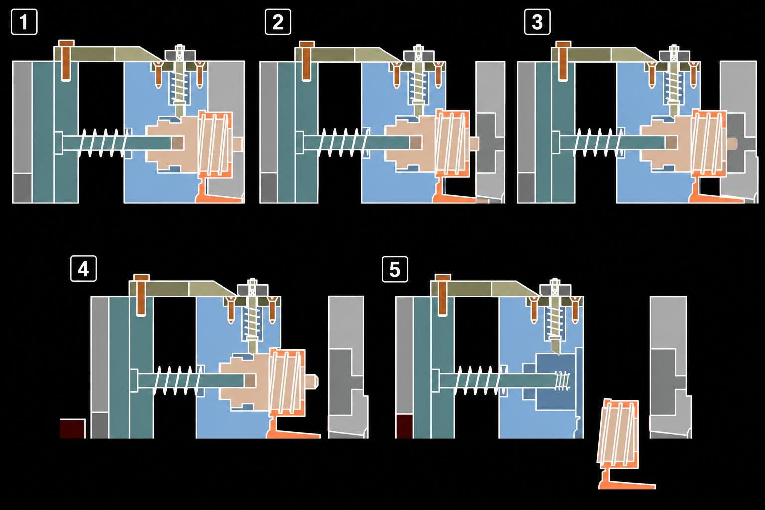
Mechanism 1 – Motor Driven Threaded Core
Motor-driven systems use an electric motor, gear train, and rotating threaded core to automatically release the molded component.
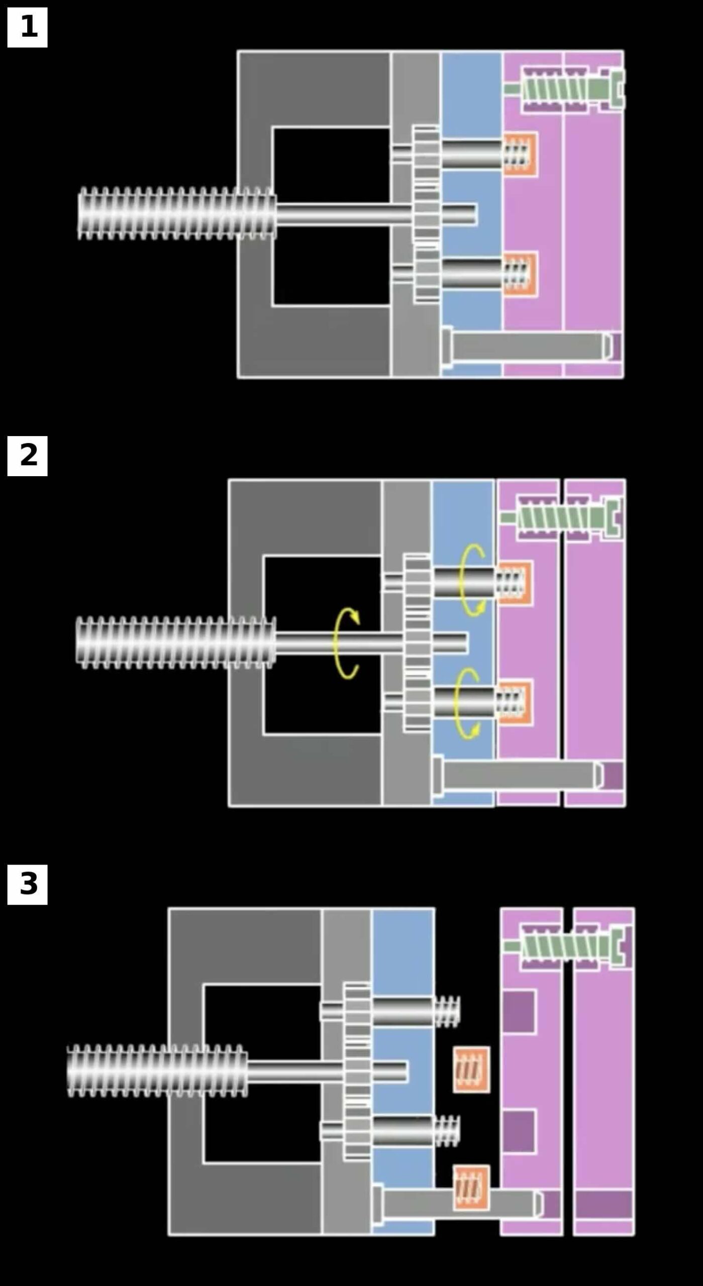
Mechanism 2 – Rack and Pinion Unthreading Type 1
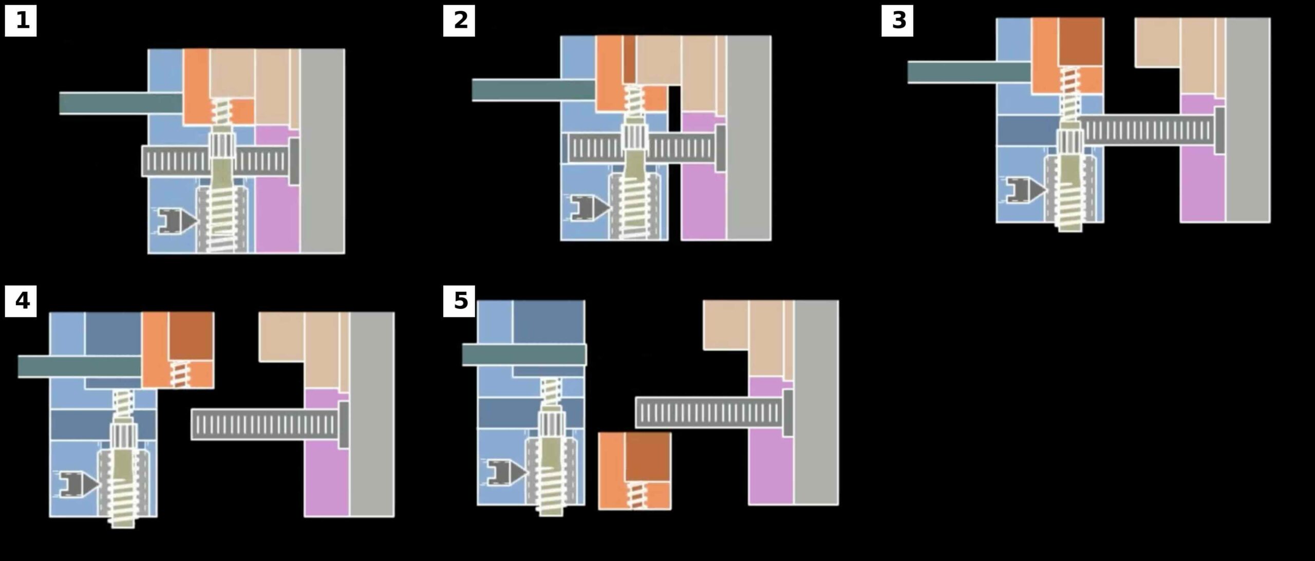
A rack mechanism converts mold opening movement into rotational motion of the threaded core.
Mechanism 3 – Hydraulic Continuous Internal Thread Unscrewing
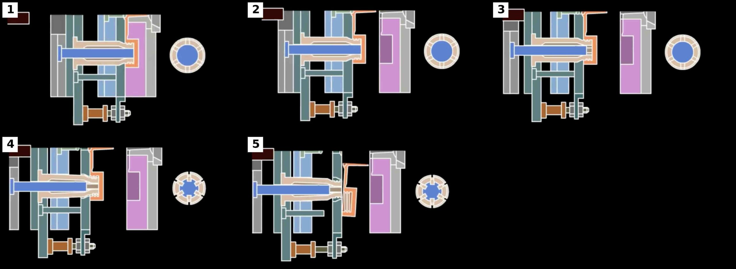
A hydraulic system continuously releases the internal thread while maintaining controlled ejection.
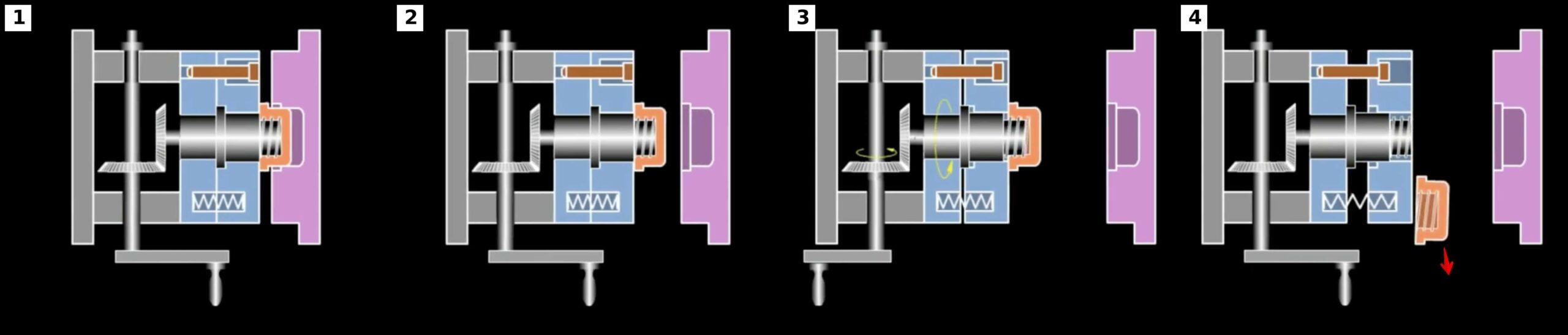
Mechanism 4 – Force Stripping
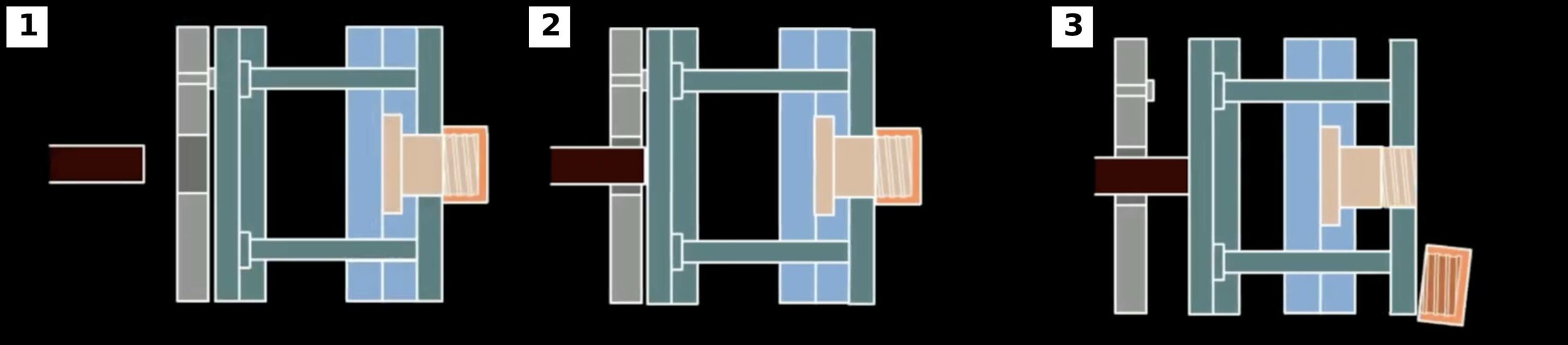
The thread is elastically deformed during ejection and released without rotation.
Mechanism 5 – Rack and Pinion Unthreading Type 2
A variation of the rack and pinion principle using additional transmission elements.
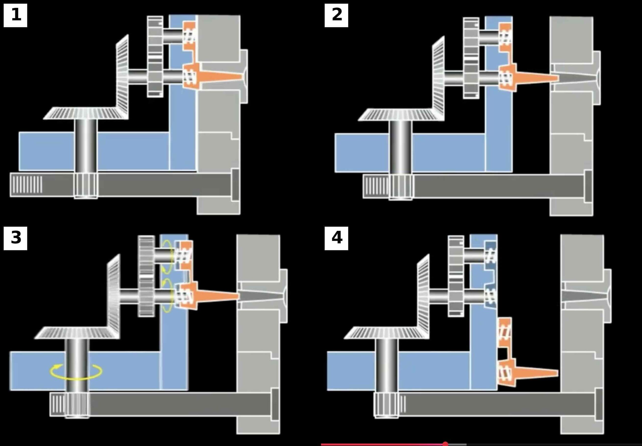
Mechanism 6 – Machine Driven Unscrewing
The motion of the injection molding machine itself is used to generate thread release.
Mechanism 7 – Hydraulic Cylinder Drive
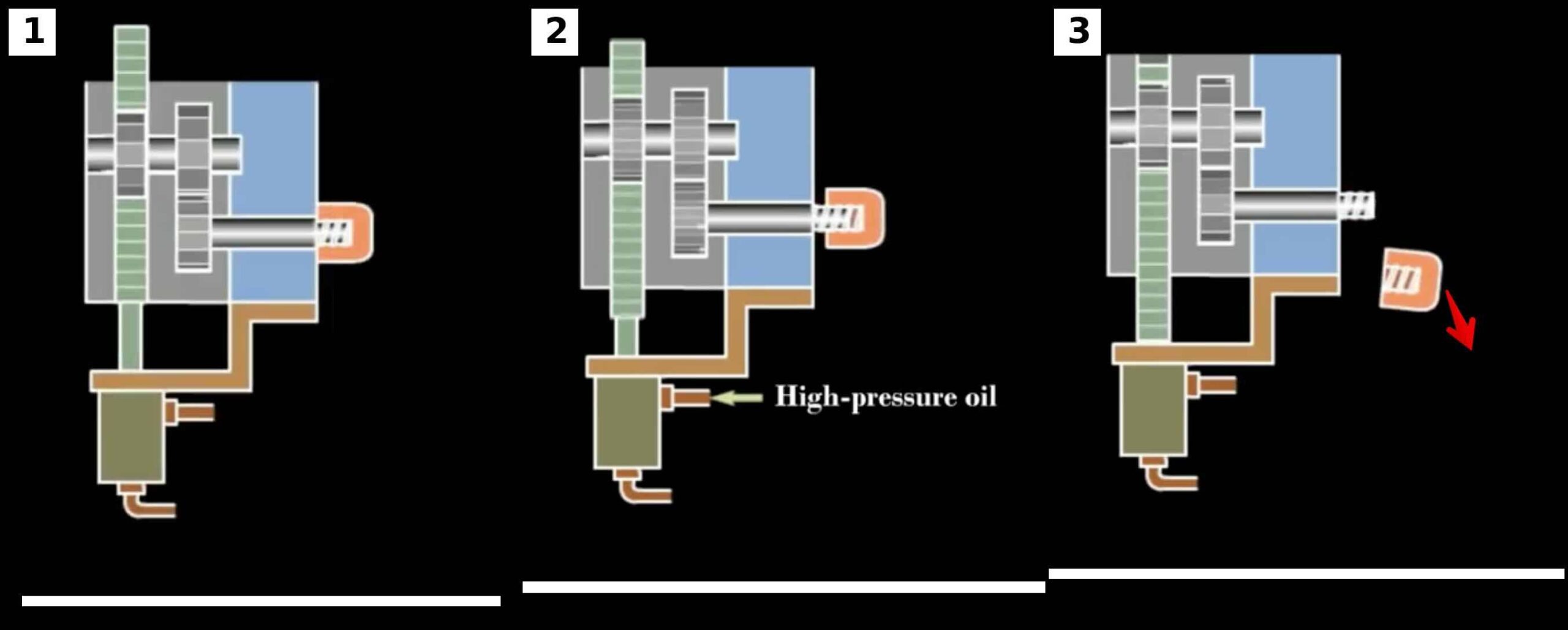
Hydraulic cylinders generate the motion required to unscrew the threaded core.
Mechanism 8 – Manual Unscrewing Type 1
The operator rotates the threaded core using a manual handle.
Mechanism 9 – Manual Unscrewing Type 2
The core is mechanically released before being manually removed from the molded component.
Mechanism 10 – Manual Unscrewing Type 3
The threaded core is manually unscrewed directly on the molding machine.
Initial Selection Matrix
| Mechanism | Cost | Complexity | Reliability | Cycle Time |
|---|---|---|---|---|
| Motor Driven | High | High | Excellent | Good |
| Rack and Pinion | Medium | Medium | Good | Good |
| Hydraulic | High | High | Excellent | Good |
| Force Stripping | Low | Low | Good | Excellent |
| Manual | Very Low | Low | Good | Poor |
This table provides a preliminary comparison only.
Final mechanism selection requires detailed engineering analysis.
What Will Be Covered in Part 2
Part 2 introduces the engineering calculations that form the foundation of every thread unscrewing system.
Topics include:
- Thread pitch
- Thread engagement length
- Number of turns
- Unscrewing angle
- Core travel
- Rack travel
- Rotational speed
- Basic torque calculations
These calculations will be used throughout the remaining articles to dimension and compare all ten thread unscrewing mechanisms.
Part 2 – Thread Geometry, Unscrewing Travel and Torque Calculations
In Part 1, we introduced the ten major thread unscrewing mechanisms used in injection molds and classified them according to their operating principles.
Before selecting a motor, hydraulic cylinder, rack and pinion system, or manual mechanism, the engineer must determine the basic motion requirements of the thread.
Every unscrewing mechanism ultimately performs the same task:
It rotates the thread a sufficient number of turns to completely disengage the molded part from the core.
This chapter provides the engineering calculations that form the foundation of all thread unscrewing systems.
Understanding Thread Geometry
Before any calculations can begin, the designer must understand four key thread parameters.
Major Diameter
The major diameter is the largest diameter of the thread.
Examples:
- Bottle cap thread = 38 mm
- Pipe fitting thread = 50 mm
- Connector thread = 24 mm
The major diameter strongly influences:
- Required torque
- Mold size
- Core rigidity
- Cooling requirements
Pitch
Pitch is the distance between adjacent thread crests.
Example:
Pitch = 3 mm
This means one complete revolution moves the thread:
3 mm
along its axis.
Pitch directly determines the number of turns required for release.
Thread Engagement Length
Thread engagement length is the axial distance over which the thread remains engaged.
Example:
Thread Engagement Length = 12 mm
The greater the engagement length:
- The more turns required
- The higher the friction
- The longer the unscrewing cycle
Number of Starts
Most molded threads are:
Single Start Threads
However, some closures use:
- Double start threads
- Triple start threads
Multi-start threads reduce the number of required turns.
Calculating the Number of Turns
The first calculation in every thread unscrewing system is determining the number of revolutions required to release the part.
Formula:
Number of Turns = Thread Engagement Length / Thread Lead
For single-start threads:
Lead = Pitch
Example 1
Input Data
Thread Engagement Length = 12 mm
Pitch = 3 mm
Calculation
Number of Turns = 12 / 3
Number of Turns = 4
Result
The threaded core must rotate:
4 complete revolutions
before the molded part is released.
Example 2
Input Data
Thread Engagement Length = 15 mm
Pitch = 2.5 mm
Calculation
Number of Turns = 15 / 2.5
Number of Turns = 6
Result
The threaded core must rotate:
6 complete revolutions
before release.
Calculating Unscrewing Angle
Many mechanical systems require angular rotation calculations.
Formula:
Unscrewing Angle = Number of Turns × 360
Example
Number of Turns = 4
Calculation
Unscrewing Angle = 4 × 360
Unscrewing Angle = 1440 degrees
Result
The threaded core must rotate:
1440 degrees
to completely disengage the thread.
Why Thread Pitch Matters
Many engineers focus only on thread diameter.
In reality, thread pitch often has a larger impact on mold performance.
Consider two examples:
Part A
Diameter = 38 mm
Pitch = 3 mm
Engagement Length = 12 mm
Required Turns = 4
Part B
Diameter = 38 mm
Pitch = 1 mm
Engagement Length = 12 mm
Required Turns = 12
The second design requires:
Three times more rotation
which significantly increases:
- Cycle time
- Wear
- Energy consumption
This demonstrates why coarse thread designs are often preferred in injection molding.
Calculating Core Travel
During unscrewing, the threaded core moves axially relative to the molded part.
Core Travel equals:
Thread Engagement Length
Therefore:
Core Travel = Thread Engagement Length
Example
Thread Engagement Length = 12 mm
Result
Core Travel = 12 mm
This value is critical when designing:
- Hydraulic systems
- Rack systems
- Motor-driven systems
Calculating Rotational Speed
The engineer must determine how quickly the thread will be released.
Formula:
RPM = Required Turns × 60 / Unscrewing Time
Example
Required Turns = 4
Desired Unscrewing Time = 1.5 seconds
Calculation
RPM = 4 × 60 / 1.5
RPM = 160
Result
The threaded core must rotate:
160 RPM
to achieve release in 1.5 seconds.
Calculating Thread Surface Speed
Surface speed affects:
- Wear
- Heat generation
- Lubrication requirements
Formula:
Surface Speed = 3.1416 × Diameter × RPM / 1000
Surface Speed is expressed in meters per minute.
Example
Diameter = 38 mm
RPM = 160
Calculation
Surface Speed = 3.1416 × 38 × 160 / 1000
Surface Speed = 19.1 m/min
Result
The thread surface moves at:
19.1 meters per minute
during unscrewing.
Introduction to Unscrewing Torque
Torque is one of the most important parameters in thread unscrewing systems.
Every mechanism must generate enough torque to overcome:
- Plastic shrinkage
- Thread friction
- Mold contamination
- Wear
An undersized system will stall.
An oversized system increases cost unnecessarily.
Understanding Torque
Torque is a rotational force.
Formula:
Torque = Force × Radius
Where:
Torque = Nm
Force = N
Radius = m
Example
Thread Friction Force = 600 N
Effective Radius = 20 mm
Convert Radius:
20 mm = 0.020 m
Calculation
Torque = 600 × 0.020
Torque = 12 Nm
Result
The mechanism must generate at least:
12 Nm
of torque.
Safety Factors
Real molds never operate under ideal conditions.
Friction varies due to:
- Mold temperature
- Resin type
- Wear
- Lubrication
- Contamination
For this reason, safety factors are required.
Recommended Design Safety Factors:
Manual Systems
Safety Factor = 1.5
Rack and Pinion Systems
Safety Factor = 2.0
Motor Driven Systems
Safety Factor = 2.0
Hydraulic Systems
Safety Factor = 2.5
Example
Calculated Torque = 12 Nm
Safety Factor = 2
Calculation
Design Torque = 12 × 2
Design Torque = 24 Nm
Result
The mechanism should be designed for:
24 Nm
minimum torque capacity.
Engineering Parameters Required for Every Mechanism
Regardless of which of the ten mechanisms is selected, the following values must always be calculated:
□ Major Diameter
□ Pitch
□ Thread Engagement Length
□ Number of Turns
□ Unscrewing Angle
□ Core Travel
□ Rotational Speed
□ Surface Speed
□ Required Torque
□ Design Torque
These values form the foundation of all subsequent calculations.
Part 3 – Gear Ratios, Rack Travel, Shaft Sizing and Power Requirements
In Part 2, we calculated the fundamental parameters required by every thread unscrewing system:
- Number of turns
- Unscrewing angle
- Core travel
- Rotational speed
- Basic torque requirements
These calculations define what the mechanism must achieve.
The next step is determining how to achieve it mechanically.
Whether the mold uses a motor, rack and pinion system, hydraulic cylinder, or machine-driven mechanism, the designer must determine:
- Gear ratios
- Rack travel
- Shaft dimensions
- Key dimensions
- Spline dimensions
- Power requirements
These calculations transform theoretical thread requirements into a real mechanical system.
Mechanical Power Flow in Unscrewing Systems
Every unscrewing mechanism follows the same energy path.
Power Source
↓
Transmission System
↓
Rotating Shaft
↓
Threaded Core
↓
Plastic Part
The power source may be:
- Electric motor
- Hydraulic cylinder
- Machine opening movement
- Manual operator
The transmission system may be:
- Spur gears
- Bevel gears
- Rack and pinion
- Splines
- Keys
Regardless of design, the engineering calculations remain similar.
Gear Ratio Fundamentals
Most unscrewing systems use gears to convert speed and torque.
Gear Ratio Formula
Gear Ratio = Driven Gear Teeth / Driving Gear Teeth
Example 1
Driving Gear
20 Teeth
Driven Gear
60 Teeth
Calculation
Gear Ratio = 60 / 20
Gear Ratio = 3
Result
Output Speed = Input Speed / 3
Output Torque = Input Torque × 3
The system gains torque but loses speed.
Why Gear Ratios Matter
A thread may require:
- High torque
- Low speed
while a motor typically provides:
- High speed
- Low torque
The gear train converts motor output into usable unscrewing motion.
Example:
Motor Speed = 1500 RPM
Required Core Speed = 150 RPM
Calculation
Gear Ratio = 1500 / 150
Gear Ratio = 10
Result
A 10:1 reduction ratio is required.
Rack and Pinion Systems
Mechanisms 2 and 5 use rack and pinion systems.
A rack converts linear movement into rotation.
This is one of the most common solutions in injection molds because it uses mold opening movement as the power source.
Rack Travel Calculation
One complete revolution of a gear requires rack movement equal to the pitch circle circumference.
Formula
Circumference = 3.1416 × Pitch Circle Diameter
Example
Pinion Diameter = 50 mm
Calculation
Circumference = 3.1416 × 50
Circumference = 157.1 mm
Result
The rack must move:
157.1 mm
for one complete revolution.
Rack Travel for Thread Release
Formula
Rack Travel = Circumference × Number of Turns
Example
Pinion Diameter = 50 mm
Required Turns = 4
Calculation
Rack Travel = 157.1 × 4
Rack Travel = 628.4 mm
Result
The rack must move:
628.4 mm
to completely release the thread.
This explains why fine-pitch threads can become problematic in rack-driven systems.
Gear Torque Calculation
The designer must determine the torque delivered by the gear train.
Formula
Output Torque = Input Torque × Gear Ratio
Example
Motor Torque = 8 Nm
Gear Ratio = 5
Calculation
Output Torque = 8 × 5
Output Torque = 40 Nm
Result
The threaded core receives:
40 Nm
of torque.
Power Requirements
Power determines motor size.
Formula
Power (kW) = Torque × RPM / 9550
Example
Torque = 40 Nm
Speed = 150 RPM
Calculation
Power = 40 × 150 / 9550
Power = 0.63 kW
Result
Required Motor Power = 0.63 kW
A motor larger than this value should be selected to provide a safety margin.
Shaft Design Fundamentals
The rotating shaft transmits torque between the drive system and the threaded core.
Improper shaft sizing leads to:
- Torsional failure
- Excessive deflection
- Fatigue cracking
- Premature wear
The shaft is one of the most critical components in any unscrewing system.
Torsional Shaft Stress
A shaft under torque experiences shear stress.
Formula
Shear Stress = 16 × Torque / (3.1416 × Diameter³)
Where:
Torque = Nmm
Diameter = mm
Stress = MPa
Example
Torque = 40 Nm
Convert Torque
40 Nm = 40,000 Nmm
Assume:
Diameter = 20 mm
Calculation
Shear Stress = (16 × 40,000) / (3.1416 × 20³)
Shear Stress = 25.5 MPa
Result
Shaft Shear Stress = 25.5 MPa
The designer must compare this value with allowable material stress.
Preliminary Shaft Diameter Estimation
A useful design formula is:
Shaft Diameter = Cube Root of
(16 × Torque) / (3.1416 × Allowable Stress)
Example
Torque = 40,000 Nmm
Allowable Stress = 60 MPa
Calculation
Diameter ≈ 15 mm
Engineering Practice
Select Next Standard Diameter
Chosen Diameter = 20 mm
The larger diameter improves stiffness and reliability.
Key Design Fundamentals
Most gears are connected to shafts using keys.
A key transmits torque between:
- Shaft
- Gear hub
Improper key sizing is a common cause of failure.
Key Force Calculation
Formula
Force = Torque / Radius
Example
Torque = 40 Nm
Radius = 15 mm
Convert Radius
15 mm = 0.015 m
Calculation
Force = 40 / 0.015
Force = 2667 N
Result
The key must transmit:
2667 N
of force.
Key Compressive Stress
According to standard key calculations, the key must be checked for bearing stress and shear stress.
For preliminary design:
Compressive Stress = Force / Contact Area
Where:
Contact Area = Key Length × Key Height
Example
Force = 2667 N
Key Length = 30 mm
Key Height = 4 mm
Area = 30 × 4
Area = 120 mm²
Calculation
Stress = 2667 / 120
Stress = 22.2 MPa
Result
Key Bearing Stress = 22.2 MPa
Splined Connections
For high-cycle molds, splines are often preferred over keys.
Advantages:
- Better load distribution
- Higher torque capacity
- Reduced backlash
- Improved fatigue life
The spline design procedures discussed in mechanical engineering references can be applied when torque exceeds the capability of conventional keys.
Engineering Example
M38 Closure Cap
Input Data
Thread Diameter = 38 mm
Pitch = 3 mm
Engagement Length = 12 mm
Required Turns = 4
Required Torque = 15 Nm
Safety Factor = 2
Step 1
Design Torque
Design Torque = 15 × 2
Design Torque = 30 Nm
Step 2
Required Core Speed
Target Unscrewing Time = 2 seconds
RPM = 4 × 60 / 2
RPM = 120
Step 3
Power Requirement
Power = 30 × 120 / 9550
Power = 0.38 kW
Step 4
Gear Ratio
Motor Speed = 1200 RPM
Gear Ratio = 1200 / 120
Gear Ratio = 10
Step 5
Output Torque
Output Torque = 3 × 10
Output Torque = 30 Nm
Result
Preliminary System Requirements
- Core Speed = 120 RPM
- Design Torque = 30 Nm
- Motor Power = 0.38 kW
- Gear Ratio = 10:1
- Preliminary Shaft Diameter = 20 mm
These values form the basis for detailed design.
Design Checklist
Before selecting any unscrewing mechanism, verify:
□ Number of turns calculated
□ Unscrewing angle calculated
□ Rack travel calculated
□ Gear ratio calculated
□ Required torque calculated
□ Design torque calculated
□ Motor power calculated
□ Shaft diameter verified
□ Key design verified
□ Spline design verified
□ Safety factor applied
Part 4 – Mechanism Selection, Reliability, Cost Analysis and Design Best Practices
In Parts 1, 2 and 3, we established the engineering foundations of thread unscrewing systems.
We examined:
- The challenges of molding threaded parts
- The classification of ten common mechanisms
- Thread geometry calculations
- Unscrewing travel calculations
- Gear ratios
- Rack travel
- Shaft sizing
- Key sizing
- Power requirements
At this stage, a designer can begin sizing a mechanism.
However, a technically correct design is not necessarily the best design.
The final step is selecting the most appropriate mechanism for the application.
The most successful mold designs balance:
- Performance
- Cost
- Reliability
- Maintainability
- Production volume
- Expected mold life
This chapter focuses on practical engineering decision-making.
The Biggest Mistake in Unscrewing Mold Design
Many engineers select a mechanism based solely on technical capability.
For example:
A servo-driven unscrewing system may technically perform better than a manual system.
However:
If the mold produces only 5,000 parts per year, the servo system may never recover its additional cost.
Similarly:
A force-stripping design may appear inexpensive.
However:
If thread damage causes a 5% scrap rate, the total production cost may become much higher than a motor-driven solution.
The correct question is not:
“Can this mechanism work?”
The correct question is:
“Is this the most economical and reliable solution over the life of the mold?”
Selecting the Correct Mechanism
The following factors should always be evaluated.
Production Volume
Production volume is often the most important parameter.
Low Production Volume
Typical Range
- Prototype molds
- Service parts
- Specialty products
Production
Less than 50,000 parts per year
Recommended Systems
- Mechanism 8
- Mechanism 9
- Mechanism 10
Manual systems are often the most economical choice.
Medium Production Volume
Typical Range
50,000 to 500,000 parts per year
Recommended Systems
- Mechanism 2
- Mechanism 5
- Mechanism 6
Mechanical systems generally provide the best balance between cost and performance.
High Production Volume
Typical Range
More than 500,000 parts per year
Recommended Systems
- Mechanism 1
- Mechanism 3
- Mechanism 7
Fully automatic systems become economically attractive.
Thread Complexity
Not all threads are equal.
The geometry of the thread strongly influences mechanism selection.
Simple Threads
Characteristics
- Large pitch
- Short engagement
- Flexible material
Possible Solutions
- Force stripping
- Manual unscrewing
Medium Complexity Threads
Characteristics
- Moderate pitch
- Moderate engagement
- Standard engineering materials
Possible Solutions
- Rack and pinion systems
- Machine-driven systems
Complex Threads
Characteristics
- Long engagement
- Fine pitch
- Deep threads
- High shrinkage materials
Recommended Solutions
- Motor-driven systems
- Hydraulic systems
Material Considerations
Material selection has a major influence on thread release.
Polypropylene (PP)
Advantages
- Flexible
- Good elastic recovery
- Excellent force stripping capability
Common Applications
- Closure systems
- Packaging
Suitable Mechanisms
- Mechanism 4
- Mechanism 1
- Mechanism 2
High Density Polyethylene (HDPE)
Advantages
- Flexible
- Tough
- Good recovery characteristics
Suitable Mechanisms
- Force stripping
- Mechanical systems
Nylon (PA)
Characteristics
- Higher stiffness
- Higher friction
- Greater shrinkage forces
Suitable Mechanisms
- Rack systems
- Motor-driven systems
- Hydraulic systems
Acetal (POM)
Characteristics
- Excellent wear resistance
- High dimensional stability
Suitable Mechanisms
- Mechanical systems
- Hydraulic systems
Force stripping becomes more difficult.
Reliability Comparison
Reliability should always be evaluated over the expected mold life.
Mechanism 1
Motor Driven System
Reliability
Excellent
Primary Wear Components
- Bearings
- Gears
- Couplings
Expected Service Life
Very high when properly maintained
Mechanism 2
Rack and Pinion Type 1
Reliability
Good
Primary Wear Components
- Rack teeth
- Gear teeth
- Guide components
Mechanism 3
Hydraulic Continuous Unscrewing
Reliability
Excellent
Primary Wear Components
- Hydraulic seals
- Bearings
- Sliding surfaces
Mechanism 4
Force Stripping
Reliability
Excellent
Primary Wear Components
Almost none
Risk shifts to:
- Part quality
- Thread damage
Mechanisms 8, 9 and 10
Manual Systems
Reliability
Excellent
Reason
Very few moving components
However:
Productivity remains limited.
Cost Comparison
The following comparison assumes a single-cavity mold.
| Mechanism | Relative Cost |
|---|---|
| Force Stripping | Very Low |
| Manual Systems | Low |
| Rack and Pinion | Medium |
| Machine Driven | Medium |
| Motor Driven | High |
| Hydraulic | Very High |
The exact values vary significantly between projects.
However, the ranking generally remains valid.
Maintenance Considerations
Maintenance costs are often overlooked during design.
A system requiring frequent maintenance can become more expensive than a more complex mechanism with superior reliability.
Low Maintenance Systems
- Force stripping
- Manual systems
These systems contain very few wear components.
Medium Maintenance Systems
- Rack and pinion systems
- Machine-driven systems
Periodic inspection is recommended.
High Maintenance Systems
- Hydraulic systems
- Motor-driven systems
Maintenance items include:
- Bearings
- Seals
- Gear lubrication
- Drive components
Common Design Mistakes
The following errors appear frequently in unscrewing molds.
Mistake 1
Ignoring Thread Pitch
Many designers focus only on diameter.
Pitch often has a greater influence on:
- Number of turns
- Cycle time
- Wear
Mistake 2
Underestimating Torque
Design calculations should always include safety factors.
Unexpected increases in friction are common.
Mistake 3
Selecting an Oversized System
A hydraulic or servo solution is not automatically better.
The simplest system capable of meeting requirements is often the best solution.
Mistake 4
Ignoring Maintenance Access
Many molds are difficult to service.
Components requiring replacement should be easily accessible.
Mistake 5
Ignoring Mold Life
A design suitable for:
50,000 cycles
may not survive:
15 million cycles
Reliability must always be considered.
Engineering Selection Workflow
The following workflow is recommended for all threaded mold projects.
Step 1
Determine thread geometry.
Step 2
Calculate:
- Turns
- Travel
- Torque
Step 3
Determine annual production volume.
Step 4
Determine target mold life.
Step 5
Evaluate material flexibility.
Step 6
Compare mechanism families.
Step 7
Select preliminary mechanism.
Step 8
Complete detailed calculations.
Step 9
Perform reliability review.
Step 10
Finalize design.
Final Design Checklist
Before releasing an unscrewing mold design, verify:
□ Thread geometry validated
□ Number of turns calculated
□ Unscrewing angle calculated
□ Core travel verified
□ Torque calculated
□ Safety factor applied
□ Gear ratio verified
□ Shaft diameter verified
□ Key design verified
□ Spline design verified
□ Production volume evaluated
□ Mold life evaluated
□ Maintenance access verified
□ Reliability reviewed
□ Mechanism selection justified
Conclusion
Thread unscrewing systems are among the most challenging mechanisms used in injection molds.
Successful designs require much more than simply rotating a threaded core.
The engineer must balance:
- Thread geometry
- Torque requirements
- Cycle time
- Cost
- Reliability
- Maintenance
- Production volume
The ten mechanisms presented throughout this article each offer unique advantages and limitations.
The best solution is rarely the most sophisticated mechanism.
Instead, the best solution is the one that provides the required performance with the lowest total cost of ownership over the life of the mold.