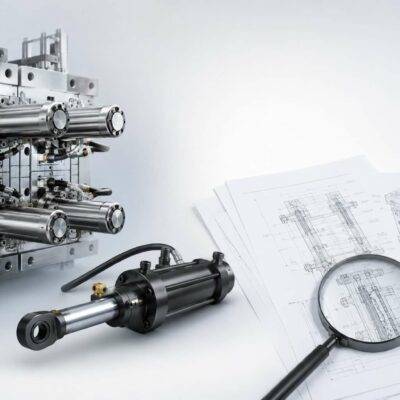
In the injection molding industry, a damaged hydraulic cylinder is often treated as the problem itself. In reality, it is usually just the visible symptom of a deeper engineering issue.
Recently, Vega Technical Dep. was asked to support a customer identified here only as A.A., a major automotive supplier, facing repeated failures of hydraulic cylinders installed on a large injection mold. Production had stopped, component quality was at risk, and the root cause was not immediately clear.
Rather than focusing only on replacing damaged components, Vega’s engineering team performed a complete technical investigation of the mold, hydraulic system, and molding process.
This case perfectly illustrates why successful troubleshooting requires engineering analysis rather than assumptions.
The Initial Situation
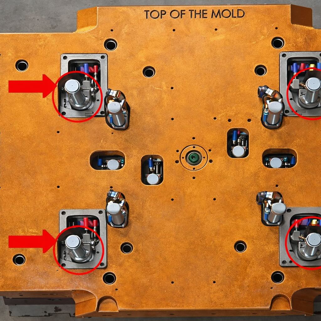
The mold contained four hydraulic cylinders responsible for moving side actions during the molding cycle.
The customer reported:
- Repeated cylinder damage
- Bent and overloaded rods
- Production downtime
- Difficulty identifying the actual cause
At first glance, the failure appeared to be related to cylinder quality or manufacturing defects. However, experience has taught us that hydraulic cylinders rarely fail without a reason.
The first step was therefore to determine the actual forces acting on the mechanism.
Engineering Begins with Data
Our technical department requested:
- Complete 3D mold assembly drawings
- Plastic part geometry
- Hydraulic circuit information
- Injection machine operating parameters
- Oil flow and pressure data
Once the information was collected, a complete force analysis was performed.

Step 1: Injection Pressure Force Analysis
During the molding process, molten plastic generates significant pressure inside the cavity.
Every moving component exposed to this pressure experiences a corresponding mechanical load.
By analyzing the geometry of the side core and the exposed projected area, Vega engineers calculated:
- Effective frontal surface approximately 8 cm²
- Estimated cavity pressure approximately 550 bar
This resulted in a thrust load exceeding 4,400 kgf acting on the moving element.
Many mold designers focus only on cylinder force while neglecting the actual pressure generated by the injected polymer. In reality, cavity pressure frequently becomes the dominant design factor.
Step 2: Stripping Force Analysis
Injection pressure alone was not sufficient to explain the failures.
The next investigation focused on extraction forces.
The molded component was produced using:
- Polypropylene (PP)
- 30% glass fiber reinforcement
Glass-filled materials generally exhibit higher friction and stronger adhesion against steel mold surfaces.
Using the component geometry and side core dimensions, Vega calculated:
- Side surface area approximately 194 cm²
- Draft angle 2°
- Estimated adhesion coefficient 10 kg/cm²
The resulting extraction force was approximately 1,940 kgf.
This value represented the minimum force required to reliably pull the side core away from the molded part.
Step 3: Comparing Required Force with Available Force
At this point, the engineering team compared the actual application requirements with the installed cylinder capabilities.
The mold was equipped with cylinders capable of generating approximately:
1,263 kgf of pulling force at the operating pressure.
However, calculations demonstrated that the application required nearly:
1,940 kgf.
In other words, the cylinders were undersized by more than 50%.
The cylinders were not failing because they were defective.
They were failing because they were being asked to perform work beyond their design capability.
This distinction is crucial.
A component operating continuously beyond its design limits may survive for some time, but fatigue, deformation, and eventual failure become inevitable.
Step 4: Hydraulic Dynamics Investigation
The analysis did not stop there.
The customer had provided screenshots from a modern injection molding machine showing a hydraulic flow rate of approximately 120 liters per minute.
Since four cylinders were operating simultaneously, each cylinder was receiving roughly:
25 liters per minute.
For small hydraulic cylinders, this value is extremely high.
Excessive flow rates create:
- High rod acceleration
- Violent direction changes
- Increased impact loads
- Pressure spikes
- Seal stress
- Dynamic loading on internal components
Many engineers concentrate only on hydraulic pressure.
However, pressure determines force.
Flow determines speed.
Speed determines kinetic energy.
And kinetic energy often becomes the true source of mechanical damage.
In this case, the cylinders were not only undersized, they were also being operated at unusually high speeds.
The combination proved particularly destructive.
Why Dynamic Loads Matter
A common mistake in mold design is to evaluate only static loads.
Real molding processes are dynamic.
A side core may accelerate rapidly, stop suddenly, and reverse direction multiple times every minute.
Even when the calculated static force appears acceptable, dynamic loads can multiply the stresses acting on rods, pistons, guides, and mounting structures.
This is especially critical when:
- Large side actions are involved
- Glass-filled materials are molded
- Cycle times are aggressively reduced
- Hydraulic flow rates are increased
Ignoring these factors often leads to premature component failures.
The Recommended Solution
After completing the investigation, Vega Technical Dep. recommended replacing the existing cylinders with larger units capable of generating the required extraction force with an appropriate safety margin.
The proposed solution included:
- Larger cylinder bore
- Adequate pulling force capacity
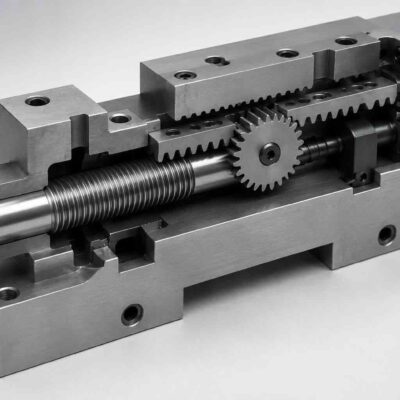
- Maintained operating stroke through stroke reduction components
- Improved reliability
- Reduced mechanical stress
The objective was not simply to replace a damaged component.
The objective was to eliminate the root cause.
Lessons Learned
This case highlights several important engineering principles:
1. Failures are often symptoms
The damaged cylinder was not the origin of the problem.
It was the visible consequence of an undersized system.
2. Proper force calculations are essential
Every mold should be evaluated considering:
- Injection pressure forces
- Stripping forces
- Friction
- Material adhesion
- Safety factors
3. Hydraulic flow matters
Pressure alone does not determine cylinder performance.
Flow rate directly influences speed, impact energy, and component life.
4. Engineering support creates value
The fastest solution is not always replacing parts.
The best solution is understanding why the parts failed.
Conclusion
At Vega, technical support goes far beyond supplying hydraulic cylinders.
Our engineering team regularly assists mold makers, injection molders, and OEM manufacturers in identifying root causes, validating designs, calculating loads, and optimizing hydraulic systems.
When production stops because of a mechanical failure, replacing components may restore operation temporarily.
Engineering analysis restores reliability permanently.
And in the long term, reliability is what keeps production running.