When engineers design hydraulic cylinders for injection molds, one of the first questions is usually:
“How much pressure is acting on the slide?”
At first glance, the answer seems straightforward.
If the cavity pressure is known, the force acting on the moving slide can be calculated directly.
However, in mold engineering, the cavity pressure is rarely the force that the hydraulic cylinder actually experiences.
Between the cavity and the hydraulic cylinder, there is a powerful mechanical transformer:
the slide angle.
Recently, Vega Technical Dep. was asked to validate the hydraulic cylinder sizing for a complex injection mold containing five independent slide mechanisms. The customer had already performed detailed calculations and requested confirmation of the selected cylinder sizes.
Rather than simply selecting cylinders from a catalog, Vega Technical Dep. reviewed the complete force analysis, validated the methodology, and confirmed the sizing calculations based on the actual geometry of the mold.
This project demonstrates why understanding force transformation is often more important than knowing the injection pressure itself.
The Initial Conditions
The mold was designed for the production of ABS components with an estimated shrinkage of:
0.5%
The estimated cavity pressure during injection was:
550 bar
The mold contained five independent slide mechanisms, each operating with different geometries and draft angles.
At first glance, a cavity pressure of 550 bar appears enormous.
And it is.
However, the hydraulic cylinders never experience this pressure directly.
From Pressure to Force
The first step in the calculation consists of converting cavity pressure into total force acting on the slide surface.
The fundamental equation is:
F = P × A
where:
- F = generated force;
- P = cavity pressure;
- A = projected frontal area.
For example, the first slide presented a projected frontal area of:
163.58 cm²
With a cavity pressure of:
550 bar
the resulting force became:
F = 89,951 kgf
At this point, many engineers might assume that the hydraulic cylinder must withstand nearly 90 tons of force.
Fortunately, this is not the case.
The Slide Angle Changes Everything
The slide was designed with a draft angle of:
22°
This angle transforms the injection force into a force component acting along the cylinder axis.
The transformation can be expressed as:
Fcylinder = Finjection × tan(α)
where:
- Fcylinder = force acting on the hydraulic cylinder;
- Finjection = force generated by cavity pressure;
- α = slide angle.
For the first slide:
tan(22°) ≈ 0.404
Therefore:
Fcylinder = 89,951 × 0.404 ≈ 36,340 kgf
The slide angle reduced the effective cylinder load by more than half.
This illustrates one of the most important principles in mold engineering:
Pressure does not determine cylinder size. Geometry does.
Why Every Slide Behaves Differently
The analysis revealed that each slide generated a different load because each one had:
- different frontal areas;
- different draft angles;
- different lateral contact surfaces;
- different extraction conditions.
Cylinder 2
Projected area:
169.84 cm²
Injection force:
93,412 kgf
Draft angle:
22°
Cylinder load:
37,738 kgf
Cylinder 3
Projected area:
160.41 cm²
Injection force:
88,226 kgf
Draft angle:
22°
Cylinder load:
35,643 kgf
Cylinder 4
Projected area:
87.78 cm²
Injection force:
48,278 kgf
Draft angle:
16°
Cylinder load:
13,842 kgf
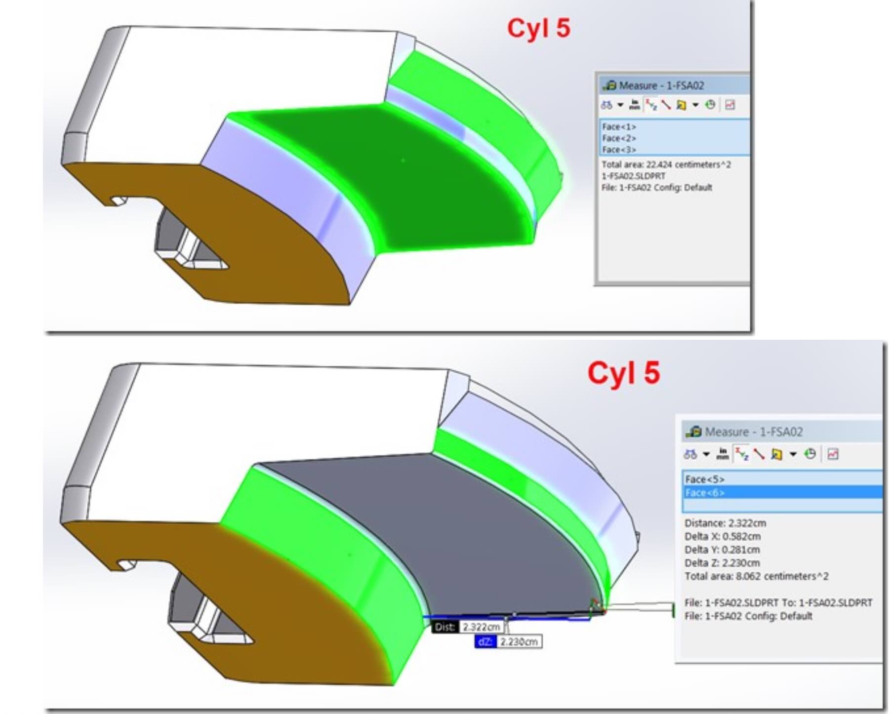
Cylinder 5
Projected area:
44.85 cm²
Injection force:
24,667 kgf
Draft angle:
25°
Cylinder load:
11,502 kgf
These calculations demonstrate how a relatively small change in slide angle can dramatically change the force transmitted to the hydraulic cylinder.
Injection Force Is Only Half of the Problem
Injection pressure generates the opening force.
However, during mold opening, the hydraulic cylinder must overcome another important load:
plastic adhesion and shrinkage forces.
The traction force can be estimated as:
Ftraction = Acontact × Kadhesion
where:
- Acontact = lateral contact area;
- Kadhesion = plastic adhesion coefficient.
For ABS, an adhesion coefficient of:
15 kg/cm²
was adopted.
For example, Cylinder 2 presented a lateral surface of:
74.336 cm²
resulting in:
Ftraction = 74.336 × 15 ≈ 1,115 kgf
Although this force is much smaller than the injection force, it becomes critical during the opening sequence.
Why the 3D Model Was Essential
One of the most important aspects of this project was that the customer supplied the complete 3D model of the mold.
This allowed Vega Technical Dep. to:
- measure the projected areas accurately;
- calculate the lateral contact surfaces;
- identify the actual slide angles;
- verify the force transmission paths;
- validate the complete engineering methodology.
Without the complete geometry, none of these calculations would have been sufficiently reliable.
Selecting the Hydraulic Cylinders
After validating the calculations, Vega Technical Dep. confirmed the following cylinder selections:
| Slide | Calculated Force | Recommended Cylinder |
|---|---|---|
| Cylinder 1 | 36,340 kgf | CG071 |
| Cylinder 2 | 37,738 kgf | CG071 |
| Cylinder 3 | 35,643 kgf | CG071 |
| Cylinder 4 | 13,842 kgf | CG045 |
| Cylinder 5 | 11,502 kgf | CG036 |
All cylinders were selected to operate at:
50 bar without preload.
The Difference Between Pressure and Force
This project demonstrates one of the most important lessons in mold engineering.
The customer initially asked:
“Which hydraulic cylinder should we use?”
The real engineering question was:
“How does the mold geometry transform pressure into force?”
The answer depended not on the hydraulic cylinder itself, but on:
- cavity pressure;
- projected area;
- slide angle;
- plastic shrinkage;
- contact surfaces;
- mold geometry.
Only after understanding these factors could the hydraulic cylinders be correctly selected.
Lessons Learned
1. Injection pressure is not the force acting on the cylinder.
2. Slide geometry transforms pressure into mechanical load.
3. Small variations in draft angle create large force variations.
4. Plastic adhesion must always be considered.
5. Complete 3D models are essential for accurate calculations.
6. Geometry often matters more than pressure.
Conclusion
At first glance, this project appeared to be a simple cylinder selection exercise.
In reality, it required a complete analysis of cavity pressure, projected areas, slide angles, plastic adhesion, and force transformation.
By validating the customer’s calculations and confirming the complete engineering methodology, Vega Technical Dep. demonstrated that successful hydraulic cylinder sizing begins not with the cylinder itself, but with understanding how forces travel through the mold.
Because in injection mold engineering:
550 bar never really means 550 bar.