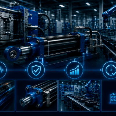
A practical engineering guide based on a real case
Choosing the correct hydraulic cylinder for an injection mold is not simply a matter of selecting a cylinder with a sufficiently large bore.
The cylinder must be capable of generating enough force to overcome the forces acting on the mold component during injection, including the pressure exerted by the molten plastic, the geometry of the punch or core, its inclination, friction and, in some applications, the adhesion of the plastic material to its lateral surfaces.
A technical case from Vega provides an excellent example.
In June 2015, a customer asked Vega to determine whether a CF056P#050 cylinder was suitable for a locking application.
The Vega Technical Department reviewed the customer’s drawing and calculated the force acting on the frontal surface of the punch. The calculation was based on:
- total frontal surface: 61 cm²;
- estimated plastic pressure in the cavity: 500 bar;
- theoretical thrust force: 30,500 kgf.
The punch was inclined by 30° relative to the cylinder axis. After taking the inclination and friction into account, Vega estimated that the effective force was reduced by approximately 40–50% and identified the CF045 as the suitable cylinder for the thrust force.
However, Vega could not complete the calculation for the traction force, because the drawing of the molded plastic part was not available. Without it, the Technical Department could not determine the actual lateral surface of the punch to which the plastic material would adhere.
This case illustrates a fundamental principle:
A hydraulic cylinder should be sized according to the actual forces generated by the molding process and the geometry of the application—not simply according to the cylinder stroke or the hydraulic system pressure.
1. Why Cylinder Force Matters in Injection Molds
Hydraulic cylinders are widely used in plastic injection molds to move components such as:
- slides;
- cores;
- punches;
- plugs;
- ejector components;
- locking elements;
- mold inserts.
During injection, molten plastic is subjected to very high pressure.
That pressure is transferred to the surfaces of the mold components in contact with the plastic.
If a hydraulic cylinder is responsible for holding or moving one of those components, the resulting force must be considered when selecting the cylinder.
A cylinder that is too small may not have sufficient force to:
- keep the component in position;
- move the component;
- overcome friction;
- overcome adhesion of the plastic;
- resist the force generated during injection.
The result can be:
- unwanted movement;
- flash;
- dimensional defects;
- incomplete movement;
- component deformation;
- excessive hydraulic pressure;
- or, in severe cases, mechanical failure.
The correct cylinder therefore has to be selected from the forces generated by the application.
2. The First Calculation: Pressure × Surface Area
The basic principle is straightforward.
If a pressure acts on a surface, the resulting force is:
where:
- F = force;
- P = pressure;
- A = effective surface area.
For an injection mold, the important question is therefore not simply:
“What is the injection pressure?”
It is:
“What effective area is exposed to that pressure?”
This distinction is fundamental.
A pressure of 500 bar acting on a small surface produces a very different force from 500 bar acting on a much larger surface.
3. The Vega Case: 61 cm² of Frontal Surface
In Case 155, the Technical Department analyzed the drawing supplied by the customer.
The total frontal surface of the punch exposed to the cavity pressure was calculated as:
61 cm².
The estimated pressure in the cavity was:
500 bar.
Because the pressure is expressed in bar and the surface in cm², the calculation can conveniently be expressed using the approximate relationship:
1 bar ≈ 1.0197 kgf/cm²
Therefore:
500 bar ≈ 509.9 kgf/cm²
and:
509.9 kgf/cm² × 61 cm² ≈ 31,100 kgf
Using the simplified engineering approximation of 1 bar ≈ 1 kgf/cm², the result is:
500 × 61 = 30,500 kgf
which is the value recorded by Vega in the original technical correspondence.
The important point is that the 30,500 kgf value is the theoretical force calculated from the frontal area and the estimated cavity pressure.
It is not automatically the force that the hydraulic cylinder must provide.
4. The Difference Between Theoretical Force and Required Cylinder Force
This distinction is extremely important.
The force calculated from:
pressure × surface
represents the force generated by the pressure acting on the specified surface.
But the cylinder may not need to counteract the entire value directly along its own axis.
The actual required cylinder force depends on the geometry of the mechanism.
In Case 155, the punch was inclined by 30° relative to the cylinder axis. Vega therefore considered the inclination together with friction and estimated that the relevant force was reduced by approximately 40–50%.
This is why a direct comparison between:
30,500 kgf
and
cylinder thrust
would be misleading.
The geometry of the application must first be considered.
5. Why the Punch Inclination Changes the Force
When a force is generated on a component that is not aligned with the cylinder axis, only part of the force acts in the direction relevant to the cylinder.
In a simplified idealized situation, a force component can be resolved using trigonometric relationships.
For example, depending on how the geometry is defined, an axial component may be expressed as:
However, this formula should not automatically be applied to Case 155 as a replacement for Vega’s calculation.
The original technical correspondence does not provide the complete mechanical geometry or the exact friction model used to arrive at the stated 40–50% reduction. It simply records Vega’s engineering assessment that the force, considering the 30° inclination and friction, was reduced by approximately 40–50%.
This is an important distinction when using historical technical cases:
The original case provides the engineering conclusion, but not enough information to reconstruct the complete force model mathematically.
Therefore, the 40–50% reduction should be treated as the technical estimate documented in the case, not as a universal correction factor for every 30° punch.
6. Never Use a Generic “30° Correction Factor”
A common mistake would be to conclude:
“Whenever a punch is at 30°, the required cylinder force is automatically 40–50% lower.”
That would be incorrect.
The actual force relationship depends on:
- punch geometry;
- direction of movement;
- contact surfaces;
- friction;
- mechanical constraints;
- direction of the plastic pressure;
- cylinder position;
- linkage geometry.
Two mechanisms can both have a 30° inclination but require completely different cylinder forces.
The 40–50% reduction is therefore specific to the configuration analyzed in Case 155.
7. The Role of Friction
Friction is another important factor in cylinder sizing.
The plastic pressure creates a force, but the actual movement of the mold component is also affected by friction between mechanical surfaces.
Friction can occur between:
- punch and guide;
- slide and mold;
- core and mold;
- moving insert and stationary component;
- other contacting surfaces.
The force required to move the component is therefore not necessarily identical to the force calculated from pressure alone.
In Case 155, Vega explicitly considered both the 30° inclination and friction when evaluating the force required by the cylinder.
8. Thrust Force and Traction Force Are Not the Same
One of the most valuable lessons in Case 155 is the distinction between thrust force and traction force.
The Technical Department was able to calculate the thrust force from the frontal surface of the punch.
However, it could not calculate the traction force because the necessary information about the plastic part was missing.
This is a very common situation in mold engineering.
The force required in one direction may be determined relatively easily from the drawing.
The force required in the opposite direction may depend on additional information that is not visible in the cylinder drawing itself.
9. Why Traction Force Can Be More Difficult to Calculate
When plastic is injected around a punch or core, the material may adhere to its surfaces.
When the punch subsequently moves, the adhesion between the plastic and the punch can create an additional resistance force.
The magnitude of this force depends on the actual geometry of the molded part.
This is why Vega requested the drawing of the plastic component.
Without knowing the geometry of the molded part, it was impossible to determine the real lateral surface of the punch to which the plastic material adhered.
This is a crucial engineering point:
The geometry of the finished plastic part can be necessary to determine the force required to retract a punch or core.
10. The Importance of the Lateral Surface
The frontal surface and the lateral surface play different roles in the analysis.
Frontal surface
The frontal surface was used in Case 155 to calculate the force generated by the cavity pressure.
The documented area was:
61 cm².
Lateral surface
The lateral surface was relevant to the traction-force calculation because plastic could adhere to this area.
Vega could not determine this area without the drawing of the plastic part.
Therefore:
The same punch can experience different forces during extension and retraction.
This is why cylinder sizing should consider both directions of movement.
11. Why the Plastic Part Drawing Matters
A customer may provide a detailed drawing of the mold but omit the drawing of the final plastic component.
From a cylinder-sizing perspective, this can be a serious limitation.
The mold drawing may show:
- punch;
- cylinder;
- guides;
- slides;
- mounting points.
But the plastic-part drawing may be necessary to understand:
- which surfaces contact the plastic;
- which surfaces are exposed to pressure;
- how much plastic surrounds the punch;
- where adhesion can occur;
- how the molded part interacts with the punch during extraction.
This is exactly why Vega requested the plastic-part drawing in Case 155.
12. What Vega Asked the Customer to Provide
Vega proposed two possible ways to obtain the missing information.
The preferred solution was:
Send the drawing of the plastic part.
Alternatively, the customer could modify the existing picture and add an arrow identifying the relevant lateral surface.
This is an excellent practical approach.
The customer does not necessarily need to create a new technical document.
Sometimes simply identifying the surface in an existing drawing is enough to allow the Technical Department to continue the calculation.
13. Selecting the Cylinder Bore
Once the required force has been determined, the cylinder bore can be evaluated.
For a single-rod hydraulic cylinder operating in extension, the theoretical piston force can be expressed as:
where:
- F = theoretical cylinder force;
- P = hydraulic pressure;
- D = piston bore diameter.
This is the theoretical force generated by the hydraulic pressure acting on the piston area.
In real applications, however, the final cylinder selection must also consider:
- operating pressure;
- pressure losses;
- friction;
- cylinder efficiency;
- required safety margin;
- dynamic conditions;
- mounting;
- mechanical geometry;
- available stroke;
- rod diameter;
- loading direction.
Therefore, the bore should not be selected simply by calculating the theoretical force and choosing the smallest cylinder that matches it.
14. Why the Customer’s CF056P#050 Was Not Simply Accepted
The original customer request was:
“The user have choose CF056P#050, Is it ok?”
Vega did not simply confirm the customer’s selection.
Instead, the Technical Department:
- examined the drawing;
- calculated the frontal surface;
- estimated the cavity pressure;
- calculated the theoretical thrust force;
- considered the punch inclination;
- considered friction;
- identified the suitable cylinder for the thrust force;
- identified the missing information required to calculate traction.
This is a much more reliable method than selecting a cylinder based only on an existing bore or stroke.
15. The Stroke Does Not Determine the Required Force
A common misconception is that a cylinder with a longer stroke is necessarily more powerful.
This is not correct.
Stroke determines how far the cylinder can move.
Bore and hydraulic pressure determine the theoretical hydraulic force.
For example, two cylinders can have:
- the same stroke;
- different bores;
and therefore very different forces.
Conversely, two cylinders can have:
- the same bore;
- different strokes;
and produce approximately the same theoretical force at the same pressure.
Therefore, the cylinder-selection process should treat stroke and force as separate design requirements.
16. The Hydraulic Pressure Is Also Not Enough
Another common mistake is to say:
“The machine works at 150 or 200 bar, therefore we can choose the cylinder from the pressure alone.”
Pressure tells us how much force a given piston area can generate.
It does not tell us how much force the application requires.
The correct sequence is:
Application forces
↓
Required cylinder force
↓
Required bore
↓
Required stroke
↓
Correct cylinder configuration
The pressure of the hydraulic system is one input into this process, not the entire calculation.
Vega’s product range is specifically designed for plastic injection molding and die-casting applications, with different cylinder families covering different types of mold movement.
17. Why the Application Category Matters
Vega categorizes its hydraulic cylinders according to their application, including:
- cart and plug movement;
- ejection plate movement;
- unscrewing;
- mechanical locking;
- die casting.
This is useful because cylinder selection is not determined by force alone.
The designer must also consider:
- how the cylinder is mounted;
- available space;
- required stroke;
- movement type;
- locking requirements;
- speed;
- sensing;
- cooling;
- hydraulic connections.
The force calculation is therefore the starting point for selecting the correct product family, not necessarily the final selection criterion.
18. What Happens If the Cylinder Is Undersized?
If the selected cylinder cannot provide sufficient force, several problems can occur.
The cylinder may:
- fail to move the component;
- stop before reaching the required position;
- move inconsistently;
- require excessive hydraulic pressure;
- experience excessive mechanical loading;
- cause production interruptions.
In an injection mold, insufficient force can also allow the component to move under injection pressure.
Depending on the application, this can contribute to:
- flash;
- dimensional inaccuracies;
- incorrect mold positioning;
- damage to mold components.
The exact consequences depend on the mechanism and application.
19. What Happens If the Cylinder Is Oversized?
Oversizing is not automatically a problem, but it can introduce disadvantages.
A larger cylinder can require:
- more installation space;
- larger mounting interfaces;
- greater oil volume;
- potentially greater flow requirements for a given speed;
- larger mechanical components.
The designer should therefore avoid simply choosing the largest available cylinder.
The goal is:
Select a cylinder that provides the required force with an appropriate engineering margin while remaining compatible with the mechanical and hydraulic constraints of the mold.
20. Force Calculation Should Start From the Mold, Not the Cylinder
The most useful principle from Case 155 is to work backwards from the application.
Instead of asking:
“Which cylinder do we have available?”
ask:
“What force does the mold mechanism require?”
Then determine:
- effective surface;
- pressure;
- theoretical force;
- geometry;
- friction;
- additional resistance;
- required cylinder force;
- cylinder bore;
- stroke;
- appropriate cylinder model.
This approach prevents the cylinder from becoming the starting point of an otherwise incomplete calculation.
21. A Practical Calculation Workflow
A useful workflow for future customer requests is the following.
Step 1 — Obtain the mold drawing
Identify:
- cylinder position;
- punch/core position;
- direction of movement;
- inclination;
- mechanical constraints.
Step 2 — Obtain the plastic-part drawing
Determine:
- surfaces exposed to pressure;
- surfaces in contact with plastic;
- possible adhesion surfaces.
Step 3 — Calculate the effective frontal area
Measure the surface directly exposed to the relevant pressure.
Step 4 — Determine the estimated plastic pressure
Use the customer’s process data or the appropriate engineering estimate.
Step 5 — Calculate theoretical force
Use:
F = P × A
with consistent units.
Step 6 — Analyze the mechanism
Consider:
- inclination;
- direction of movement;
- linkage;
- friction;
- mechanical constraints.
Step 7 — Calculate or estimate additional resistance
Particularly for retraction, investigate adhesion and other forces.
Step 8 — Determine the required cylinder force
Do not use the theoretical pressure force without considering the mechanism.
Step 9 — Select the bore
Compare the required force with the theoretical force available from the cylinder at the actual hydraulic pressure.
Step 10 — Check stroke and mounting
A cylinder with sufficient force is still unsuitable if the stroke or mounting configuration is incorrect.
22. Always Use Consistent Units
Force calculations can easily become confusing when pressure, area and force are expressed in different units.
For example, in Case 155 Vega used:
- pressure in bar;
- area in cm²;
- force in kgf.
This makes the approximate calculation particularly simple:
500 bar × 61 cm² ≈ 30,500 kgf
When using SI units, the same calculation should instead use:
- pressure in pascals;
- area in square metres;
- force in newtons.
The important rule is:
Never mix units without converting them first.
23. kgf, daN and Newtons
Historical hydraulic-cylinder calculations often use kgf, particularly in older technical documentation.
Modern engineering calculations generally use:
- N — newton;
- kN — kilonewton.
For practical engineering approximations:
1 kgf ≈ 9.81 N
Therefore:
30,500 kgf ≈ 299 kN
The exact conversion is approximately:
30,500 × 9.80665 ≈ 299,100 N
or:
≈ 299 kN
The original Vega Case 155, however, explicitly records the force as 30,500 kgf, so this is the value that should be retained when describing the historical case.
24. Why the Thrust Calculation Was Possible
The thrust calculation was possible because Vega had enough information to determine:
- frontal surface;
- estimated cavity pressure.
The correspondence records the total frontal area as 61 cm² and the estimated pressure as 500 bar.
This allowed the Technical Department to calculate the theoretical thrust force.
The later mechanical assessment could then take into account the punch inclination and friction.
This is a good example of how a technical calculation can be divided into several stages rather than trying to calculate everything simultaneously.
25. Why the Traction Calculation Was Not Possible
The traction calculation was different.
Vega explicitly stated that it could not calculate the traction force because:
- the drawing of the plastic piece was not available;
- the actual lateral surface of the punch to which the plastic material adhered could not be determined.
This is an important example of responsible engineering.
When required data are missing, the correct approach is not to invent an assumption and present the result as an exact calculation.
The correct approach is to identify the missing parameter and request it from the customer.
26. What to Do When the Customer Has No Plastic-Part Drawing
If the customer cannot provide the complete plastic-part drawing, there is still another option.
As Vega suggested in Case 155, the customer can identify the relevant lateral surface directly on the existing image by adding an arrow.
The Technical Department can then use that information to understand:
- which surface is in contact with plastic;
- which surface contributes to adhesion;
- which area needs to be considered in the traction analysis.
This is often much faster than waiting for a complete new technical drawing.
27. Do Not Confuse Cavity Pressure With Hydraulic Pressure
This distinction is essential.
In Case 155:
500 bar was the estimated plastic pressure in the cavity.
That is not necessarily the same pressure as the hydraulic pressure supplied to the cylinder.
The two pressures belong to different systems:
Plastic pressure
Pressure generated by the injection process inside the mold cavity.
Hydraulic pressure
Pressure in the hydraulic circuit driving the cylinder.
The plastic pressure is used to determine the external force acting on the mold component.
The hydraulic pressure is then used to determine how much force the selected cylinder can generate.
This distinction is fundamental to correct cylinder sizing.
28. The Complete Force Chain
A useful way to visualize the calculation is:
Plastic injection pressure
↓
Effective surface area
↓
Force generated on punch
↓
Mechanical geometry
↓
Inclination + friction + other resistances
↓
Required cylinder force
↓
Hydraulic pressure available
↓
Required cylinder bore
↓
Cylinder selection
This is the correct engineering logic.
29. Why Safety Margins Must Be Considered
The theoretical calculation should not normally be treated as the exact minimum cylinder specification without further engineering evaluation.
Real applications can experience:
- pressure variations;
- friction variation;
- temperature changes;
- dimensional tolerances;
- contamination;
- dynamic effects;
- unexpected mechanical resistance.
The appropriate safety margin depends on the application and should be determined by the responsible designer or Technical Department.
Case 155 itself does not specify a numerical safety factor, so a universal safety factor should not be attributed to this case.
The documented Vega calculation identifies the CF045 as suitable for the analyzed thrust condition after considering the punch inclination and friction.
30. Why Cylinder Selection Requires Technical Judgment
A purely mathematical calculation is not always enough.
Two applications can have the same:
- pressure;
- surface;
- nominal force;
but require different cylinders because of:
- mounting;
- stroke;
- space;
- speed;
- mechanical loads;
- locking requirements;
- temperature;
- sensing;
- hydraulic connections.
Vega’s product range includes compact, heavy-duty, long-stroke, self-locking and application-specific cylinders, reflecting these different requirements.
31. What Information Should Be Requested From the Customer?
For future cylinder-sizing requests, a standard checklist can prevent incomplete calculations.
Mold information
- mold drawing;
- section view;
- cylinder position;
- punch/core geometry;
- movement direction;
- punch inclination.
Plastic-part information
- finished-part drawing;
- plastic material;
- surface surrounding the punch;
- possible adhesion areas.
Process information
- estimated cavity pressure;
- injection pressure where relevant;
- cycle conditions;
- temperature.
Hydraulic information
- available hydraulic pressure;
- maximum operating pressure;
- flow rate;
- required cylinder speed.
Cylinder requirements
- required stroke;
- mounting configuration;
- available installation space;
- sensors;
- locking requirements.
This information allows Vega to determine whether a standard cylinder is suitable or whether a different bore or configuration should be considered.
32. A Customer Request We Should Not Answer Too Quickly
Consider a request such as:
“The customer has selected a 56 mm bore cylinder with a 50 mm stroke. Is it OK?”
The answer should not simply be:
“Yes.”
Nor should it automatically be:
“No.”
The correct answer is:
“We need to calculate the force required by the application.”
Case 155 demonstrates exactly this approach.
The customer had already selected CF056P#050, but Vega reviewed the actual application before giving its technical recommendation.
33. What Made the CF045 Suitable in the Case?
According to the original Vega correspondence, after calculating the frontal force and considering the 30° inclination and friction, the Technical Department concluded:
“The suitable cylinder is the CF045.”
The important point is not simply the model name.
The important point is why Vega arrived at that conclusion:
- determine the force generated by the plastic pressure;
- determine the effective surface;
- account for the mechanical geometry;
- account for friction;
- compare the resulting requirement with the cylinder capability.
This is the procedure that should be retained for future cases.
34. A General Example
Suppose a punch has an effective frontal area of:
40 cm²
and the estimated cavity pressure is:
400 bar
A simplified calculation gives:
400 × 40 = 16,000 kgf
This is the theoretical pressure force on that surface.
But the cylinder selection cannot yet be finalized.
We would still need to know:
- punch inclination;
- friction;
- movement direction;
- mechanical constraints;
- possible adhesion;
- hydraulic pressure available to the cylinder;
- required stroke.
The example demonstrates why:
Pressure × area is the beginning of the calculation, not the end.
35. Extension and Retraction Must Be Evaluated Separately
A cylinder may require different forces during:
Extension
The cylinder pushes the punch or core into position.
Retraction
The cylinder pulls the punch or core out of the molded component.
The forces can be very different.
In Case 155, Vega was able to evaluate the thrust condition but could not complete the traction calculation because the plastic-part geometry and lateral adhesion surface were unknown.
Therefore:
Never size a cylinder solely on the force required in one direction if the opposite direction can involve different mechanical loads.
36. Why Adhesion Can Be Important During Retraction
After injection and cooling, the plastic part can remain in contact with the punch.
Depending on the geometry and material, removing the punch may require additional force.
The relevant factors can include:
- contact area;
- surface geometry;
- material shrinkage;
- adhesion;
- friction;
- draft angles;
- cooling conditions.
Case 155 does not provide enough information to quantify these effects, which is precisely why Vega requested the plastic-part drawing.
37. The Difference Between a Calculation and an Estimate
Technical communication should clearly distinguish between:
Calculated value
A value obtained from known dimensions and specified parameters.
Estimated value
A value based on an engineering assumption.
Unknown value
A value that cannot be determined because necessary information is missing.
In Case 155:
- 61 cm² was a calculated surface area;
- 500 bar was an estimated cavity pressure;
- 30,500 kgf was the resulting theoretical thrust force;
- the 40–50% reduction was Vega’s engineering assessment considering inclination and friction;
- the traction force remained undetermined because the necessary geometry was missing.
This distinction makes technical communication much more reliable.
38. A Recommended Response to Similar Customer Requests
When a customer asks Vega to choose a hydraulic cylinder for a mold, a good technical response can follow this structure:
To select the correct cylinder, we need to calculate the force required by the application rather than relying only on the cylinder bore and stroke selected by the customer.
Please provide the mold drawing, including the punch/core geometry and its inclination, together with the drawing of the molded plastic part. We also need the estimated cavity pressure and the hydraulic pressure available to the cylinder.
From the mold drawing we can calculate the effective surface exposed to the plastic pressure and determine the corresponding force. We can then consider the mechanical geometry and friction. For the return/traction movement, we also need to evaluate the surfaces of the punch that remain in contact with the plastic.
Once these parameters are available, we can verify whether the proposed cylinder is suitable or whether a different bore is required.
This approach closely follows the reasoning used by Vega in Case 155.
39. Case 155: The Complete Engineering Logic
The original case can be summarized as follows:
Customer request
Can the selected CF056P#050 cylinder be used?
Vega analysis
Frontal punch surface:
61 cm².
Estimated cavity pressure:
500 bar.
Theoretical thrust:
30,500 kgf.
Punch inclination:
30° relative to the cylinder axis.
Effect of inclination and friction:
approximately 40–50% reduction according to Vega’s assessment.
Cylinder identified as suitable for the thrust:
CF045.
Missing information
The plastic-part drawing and the actual lateral surface of the punch in contact with the plastic were missing.
Vega’s request
Provide the plastic-part drawing or identify the relevant lateral surface directly on the existing image.
40. The Main Engineering Lesson
Case 155 provides a very useful rule for future cylinder-sizing requests:
Never select a hydraulic cylinder simply because its bore and stroke appear appropriate. First determine the force generated by the mold application.
The calculation should begin with the plastic pressure and effective surface area.
Then the designer must consider the mechanical geometry, including inclination and friction.
Finally, both thrust and traction must be evaluated whenever the cylinder operates in both directions.
If the required information is missing, the correct engineering response is to ask the customer for the missing drawing or dimensions rather than making an unsupported assumption.
That is exactly how Vega handled Case 155.
41. Final Practical Checklist
Before recommending a hydraulic cylinder for an injection-mold application, verify:
Geometry
- Mold drawing available
- Punch/core drawing available
- Direction of movement known
- Inclination known
- Mechanical constraints known
Plastic part
- Finished-part drawing available
- Pressure-exposed surface identified
- Plastic-contact surface identified
- Possible adhesion surface identified
Process
- Cavity pressure known or estimated
- Operating temperature known
- Cycle conditions known
Hydraulic system
- Available hydraulic pressure known
- Required speed known
- Required stroke known
Force calculation
- Frontal force calculated
- Mechanical geometry considered
- Friction considered
- Thrust force evaluated
- Traction force evaluated
- Appropriate engineering margin considered
Cylinder
- Bore suitable
- Stroke suitable
- Mounting suitable
- Rod suitable
- Sensors considered if required
- Locking system considered if required
42. Conclusion
Selecting a hydraulic cylinder for a plastic injection mold is fundamentally a force-calculation problem.
The hydraulic cylinder must be capable of generating the force required by the mold mechanism under the actual injection conditions.
Case 155 demonstrates the correct approach.
The Vega Technical Department started by analyzing the drawing and determining a 61 cm² frontal surface on the punch. With an estimated cavity pressure of 500 bar, this produced a theoretical thrust force of approximately 30,500 kgf.
The punch was inclined by 30° relative to the cylinder axis, and Vega considered the inclination together with friction, estimating that the relevant force was reduced by approximately 40–50%. On this basis, the Technical Department identified the CF045 as suitable for the thrust condition.
However, Vega did not pretend that the entire calculation was complete.
The traction force could not be determined because the drawing of the plastic component was missing, making it impossible to determine the actual lateral surface of the punch to which the plastic material adhered.
This is perhaps the most important lesson of the case:
Good hydraulic-cylinder sizing is not about finding a cylinder that “looks big enough.” It is about understanding the forces generated by the mold, calculating what the cylinder must actually withstand or overcome, and identifying any missing information before making a technical recommendation.
For future customer requests, the most reliable procedure is therefore:
Plastic pressure → effective surface → theoretical force → geometry → friction → adhesion/traction → required force → cylinder bore → cylinder selection.
Useful Vega References
- Vega Cylinders – Hydraulic Cylinders for Plastic Injection Molding and Die Casting — official Vega product platform and overview of hydraulic cylinders designed for injection molding and die-casting applications.
- Vega Cylinders – Hydraulic Cylinder Categories — official product categories for mold applications, including cart and plug movement, ejection and mechanical locking.
- Vega Cylinders – Hydraulic Cylinder Catalog — official catalog organized by application, including cart and plug movement, ejection, unscrewing and mechanical locking.
- Vega Cylinders – Self-Locking Hydraulic Cylinders — useful when the application requires the hydraulic cylinder to resist forces while mechanically locked.
- Vega Cylinders – Custom Hydraulic Cylinders — information on customized hydraulic-cylinder solutions when a standard configuration is not sufficient.
- Vega Cylinders – Materials and Components — information on the construction, materials and components used in Vega hydraulic cylinders.