

Why Every Core Pull Should Be Calculated Using Two Different Forces
Designing a reliable side-action mechanism is one of the most demanding engineering tasks in injection mold construction. While selecting a hydraulic cylinder may appear straightforward, many design errors originate from a misunderstanding of the loads acting on the slide during the molding cycle.
A common misconception is that a hydraulic cylinder only needs enough force to move the slide.
In reality, a self-locking hydraulic cylinder must overcome two completely different forces:
- the force generated by the pressure of the molten plastic acting on the slide during injection;
- the force required to extract the slide from the solidified plastic after cooling.
Although these forces act on the same component, they originate from different physical phenomena and must be calculated separately.
A real engineering case handled by the Vega Technical Department clearly demonstrates this principle. A customer requested assistance in selecting the appropriate self-locking hydraulic cylinders for three slides in a polypropylene injection mold. Rather than simply recommending a cylinder from the catalogue, Vega performed a complete engineering analysis by calculating both the thrust force and the traction (extraction) force for each slide before selecting the appropriate cylinder sizes.
This approach reflects one of the fundamental principles of professional mold engineering: never size a hydraulic cylinder based on only one loading condition.
Understanding the Two Different Load Conditions
During an injection molding cycle, a slide is subjected to completely different loads depending on the production stage.
During injection and packing, molten polymer exerts pressure on every exposed surface inside the cavity. Any slide forming an undercut or side feature is pushed outward by this pressure.
After cooling, the situation changes completely.
As the polymer solidifies, it shrinks around the slide. The injection pressure disappears, but another force becomes dominant: the adhesion and friction between the plastic part and the steel surface.
The hydraulic cylinder must therefore perform two independent tasks:
- Keep the slide securely closed while the cavity is under injection pressure.
- Pull the slide out of the molded part after solidification.
Although these operations occur during the same molding cycle, they require different engineering calculations.
Why Self-Locking Cylinders Are Different
A conventional hydraulic cylinder relies entirely on hydraulic pressure to resist external loads.
If oil pressure drops unexpectedly, the cylinder may move under the action of the molded part.
A self-locking hydraulic cylinder works differently.
Its internal mechanical locking system maintains the slide in position even if hydraulic pressure is temporarily lost.
This makes self-locking cylinders particularly suitable for:
- injection molds with high cavity pressure;
- deep side cores;
- large slides;
- safety-critical molding applications;
- molds operating with long holding-pressure times.
However, the locking mechanism does not eliminate the need for proper engineering calculations.
The cylinder must still be capable of generating sufficient hydraulic force during both extension and retraction.
The First Engineering Calculation: Thrust Force
The first calculation concerns the force acting on the slide while molten plastic fills the cavity.
This force depends primarily on two parameters:
- the projected area exposed to plastic pressure;
- the pressure acting on that area.
The engineering relationship is straightforward:
F = P × A
where:
- F = thrust force
- P = plastic pressure
- A = projected area exposed to the melt
This equation represents one of the most important calculations in hydraulic slide design because it determines the minimum force required to keep the slide closed during injection.
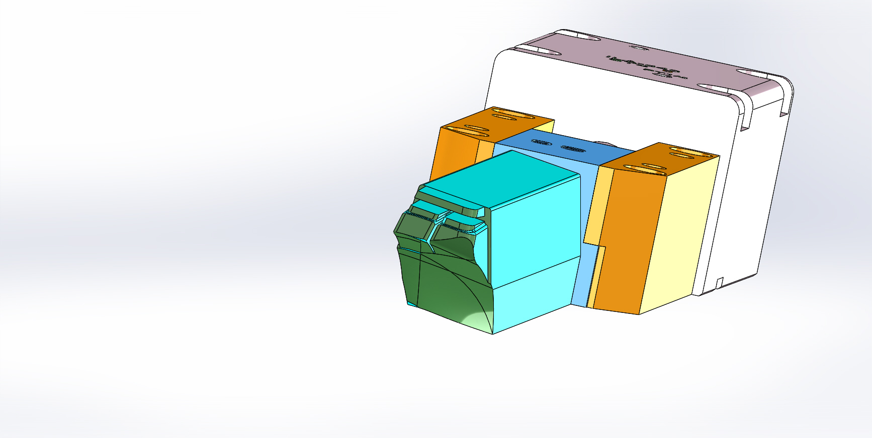
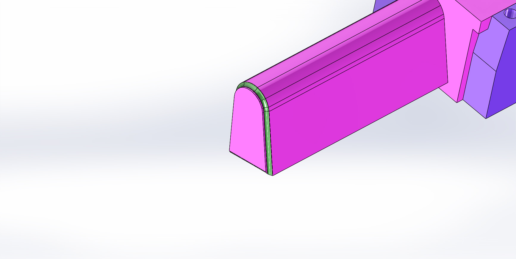
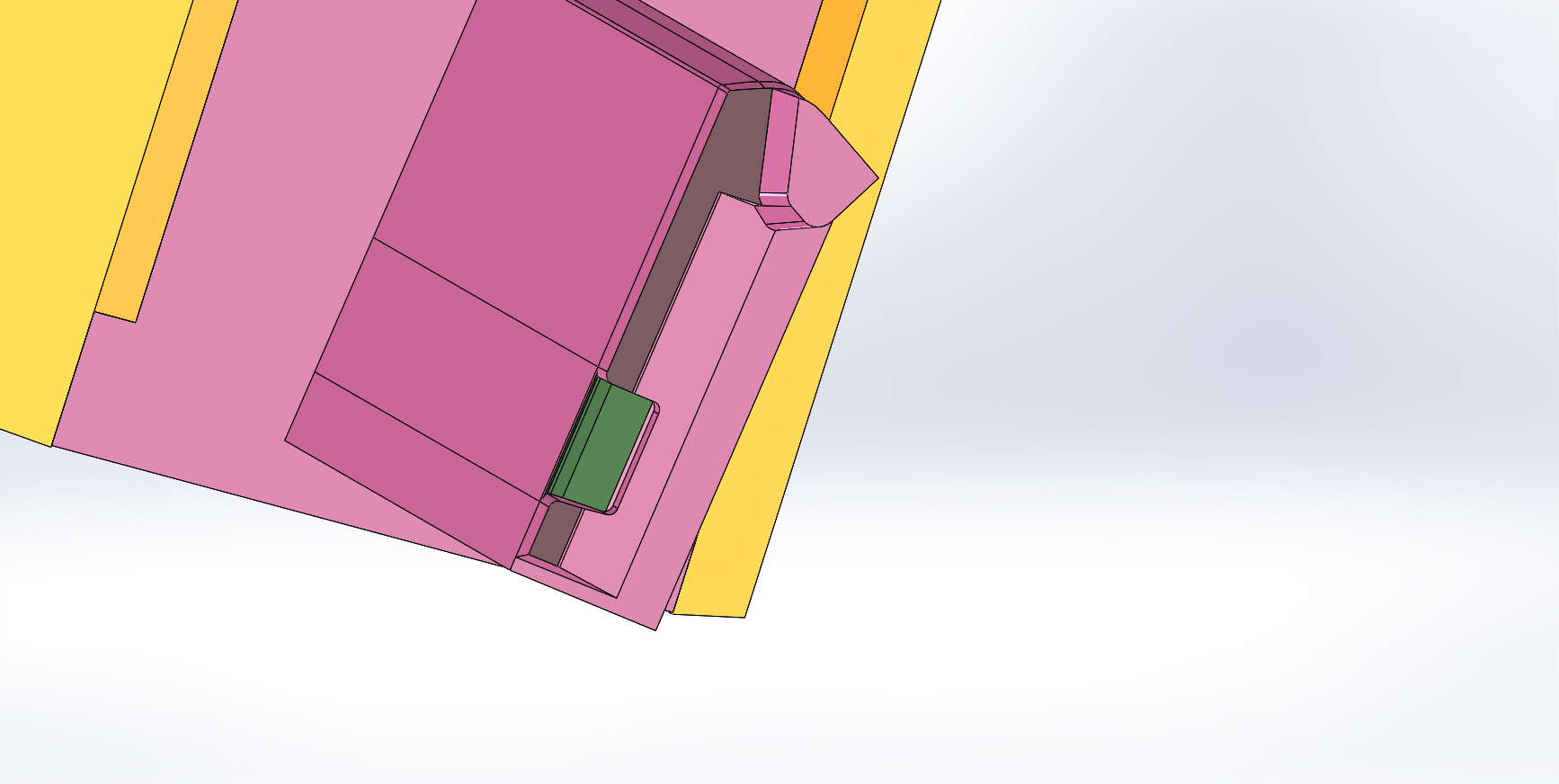
In the Vega case, the Technical Department evaluated the projected surfaces highlighted in the customer’s drawings and calculated the corresponding thrust loads before selecting the hydraulic cylinders.
Projected Area Is More Important Than Part Size
One of the most common mistakes made by inexperienced designers is assuming that a larger molded part automatically requires a larger hydraulic cylinder.
This is not necessarily true.
The cylinder is not loaded by the entire part.
It is loaded only by the surface directly exposed to cavity pressure.
Consider two different slides.
One may belong to a very large automotive component but expose only a small insert to cavity pressure.
Another may belong to a much smaller molded part yet present a large projected area directly facing the melt.
The second application may actually require the larger hydraulic cylinder.
For this reason, professional mold designers always calculate the projected area instead of estimating cylinder size based on the overall dimensions of the molded component.
The green areas shown in the customer’s CAD model represent precisely the surfaces used to determine these projected loads.
Plastic Pressure Is Not the Machine Injection Pressure
Another frequent misconception concerns injection pressure.
Machine specifications often indicate injection pressures exceeding 2,000 bar.
These values should not be used directly for hydraulic cylinder calculations.
The pressure acting on an individual slide depends on several factors, including:
- gate location;
- flow path;
- wall thickness;
- cavity filling sequence;
- pressure losses;
- packing profile;
- material viscosity.
For this engineering case, Vega adopted a design pressure of approximately 500 bar for calculating the thrust forces, a realistic engineering value for this particular polypropylene application rather than the maximum machine capability.
This distinction is extremely important.
Confusing machine injection pressure with actual cavity pressure often leads to oversized hydraulic cylinders, increased mold dimensions, unnecessary costs and reduced design efficiency.
Engineering Requires Verification, Not Assumptions
One particularly interesting aspect of the Vega response is its engineering philosophy.
After completing the calculations, the Technical Department did not simply state that the selected cylinders were correct.
Instead, it recommended that the customer independently verify the calculations using the actual mold design.
This reflects good engineering practice.
Every theoretical calculation is based on assumptions regarding:
- material properties;
- pressure distribution;
- effective contact area;
- molding conditions.
Final verification should always be performed using the complete mold geometry and the actual processing conditions.
This disciplined approach is consistent with modern mold engineering, where successful designs rely not only on formulas but also on validation, design reviews and systematic engineering practices throughout the mold development process. Industrial mold standards emphasize structured engineering reviews and validation before production release.
Looking Beyond Force Alone
At first glance, cylinder sizing appears to be a simple force calculation.
In reality, it involves mechanics, polymer behavior, safety factors and mold design principles.
Experienced mold designers know that selecting the correct self-locking cylinder is not merely a matter of choosing a larger bore.
The real objective is to balance:
- hydraulic force;
- locking capability;
- available installation space;
- slide geometry;
- mold reliability;
- production safety.
Only after understanding the thrust force can the second—and often more challenging—calculation be performed: determining the extraction force required to pull the slide away from the cooled plastic part.
Why Extraction Force Is Often More Difficult to Calculate Than Injection Force
In Part 1, we examined the first stage of sizing a self-locking hydraulic cylinder: calculating the thrust force required to keep the slide closed while molten polymer fills the cavity.
Although this calculation is fundamental, it represents only half of the engineering problem.
Once the injection cycle is complete, cavity pressure disappears.
At that moment, a completely different physical phenomenon begins to govern the hydraulic cylinder.
Instead of resisting the pressure of the molten plastic, the cylinder must now extract the slide from the solidified part.
This operation requires calculating the traction force, sometimes referred to as the extraction force.
Unlike thrust force, which mainly depends on pressure and projected area, extraction force depends on the interaction between the molded polymer and the steel surface.
For many applications, this second calculation is actually the more difficult one.
Why Plastic Shrinkage Creates Extraction Force
As the molten polymer cools, it contracts.
This shrinkage is essential because it allows the molded component to be removed from the cavity.
However, shrinkage does not always reduce the extraction force.
On side cores and slides, the opposite may occur.
The plastic contracts around the steel insert, increasing the contact pressure between the molded part and the slide.
The hydraulic cylinder must therefore overcome:
- friction between the plastic and the steel;
- adhesion between the polymer and the slide surface;
- local mechanical interference caused by part geometry.
Unlike injection pressure, these forces cannot be measured directly during production.
They must be estimated using engineering experience, material data and proven design coefficients.
This is one of the reasons why extraction force calculations often vary from one application to another, even when identical cylinders are used.
How Vega Calculated the Extraction Force
In the engineering evaluation, the Vega Technical Department treated extraction force separately from thrust force.
Instead of using the projected area exposed to cavity pressure, the calculation was based on the lateral contact surface between the molded polypropylene part and the slide.
For polypropylene, Vega adopted an adhesion coefficient of approximately 20 kg/cm².
Multiplying this coefficient by the effective contact area allowed the engineers to estimate the traction force required to withdraw each slide after cooling.
This is an important distinction.
The projected area used for thrust calculations and the contact area used for extraction calculations are rarely the same.
Using one instead of the other can lead to significant sizing errors.
Why Material Selection Influences Cylinder Size
One of the advantages of analysing real engineering cases is that they demonstrate how strongly material properties affect hydraulic cylinder selection.
In this application, the molded component was manufactured from polypropylene (PP).
Polypropylene generally exhibits relatively low adhesion compared with engineering polymers such as:
- Polyamide (PA)
- Polycarbonate (PC)
- ABS
- PC/ABS
- POM
Different polymers produce different extraction forces because they differ in:
- shrinkage behaviour;
- surface adhesion;
- coefficient of friction;
- elastic recovery after cooling.
Consequently, two molds having identical geometry may require different hydraulic cylinders simply because they process different materials.
This is why experienced mold designers never rely on geometry alone.
The molded material is always part of the engineering calculation.
Modern mold design handbooks also emphasize that material properties, shrinkage behaviour and cooling characteristics directly influence core pull design and should always be considered during engineering calculations rather than after the mold has been built.
Selecting the Correct Cylinder
After calculating both thrust and traction forces, Vega selected different self-locking cylinder sizes according to the loading conditions of each slide.
The calculations resulted in the recommendation of:
- CF045 for the higher-load applications;
- CF030 for the smaller slide.
Interestingly, the Technical Department also noted that, because the calculated loads were relatively moderate, a standard CM040 hydraulic cylinder could also represent a practical alternative in some situations.
This observation illustrates an important engineering principle.
A self-locking cylinder is not automatically the best solution for every application.
The most appropriate cylinder depends on:
- injection force;
- extraction force;
- available hydraulic pressure;
- required safety factor;
- mold geometry;
- operational reliability.
Good engineering always balances technical performance with economic efficiency.
Hydraulic Pressure Should Never Be Considered Alone
Another valuable lesson from this case concerns hydraulic pressure.
Many designers focus primarily on the available oil pressure.
In reality, pressure alone provides very little information.
A cylinder with a small piston operating at high pressure may still generate less force than a larger cylinder operating at lower pressure.
For this reason, professional cylinder selection always considers:
- piston diameter;
- effective piston area;
- rod diameter;
- available hydraulic pressure;
- extension force;
- retraction force.
Only by evaluating the complete hydraulic system can the engineer determine whether the selected cylinder provides sufficient performance.
Verification Is Part of the Design Process
One of the strongest aspects of the Vega Technical Department’s response is that the calculations were presented as engineering guidance rather than absolute values.
After recommending the appropriate cylinders, Vega advised the customer to verify the calculations against the actual mold design before finalising the project.
This reflects the methodology described in professional mold design standards.
Engineering calculations provide the foundation for cylinder selection, but final validation should always include:
- complete CAD verification;
- slide geometry review;
- confirmation of projected areas;
- confirmation of contact surfaces;
- hydraulic pressure verification;
- practical evaluation during mold trials.
Successful mold design is never based on formulas alone.
It combines theoretical calculations with engineering validation.
The Most Common Design Mistake
Perhaps the most important lesson from this engineering case is that many hydraulic cylinder sizing errors originate from confusing thrust force with traction force.
Although both forces act on the same slide, they are generated by completely different physical mechanisms.
Injection pressure determines the force required to keep the slide closed.
Material adhesion determines the force required to extract it after cooling.
Calculating only one of these conditions may produce a cylinder that performs perfectly during one phase of the molding cycle while failing during the other.
Professional mold designers therefore analyse both conditions independently before selecting the final hydraulic cylinder.
Conclusion
This real engineering case demonstrates that sizing a self-locking hydraulic cylinder involves far more than selecting a cylinder from a catalogue.
Proper engineering requires understanding the complete molding cycle.
The slide must first resist the pressure of molten polymer during injection.
It must then overcome adhesion and friction while extracting from the cooled component.
Only by independently calculating both thrust force and traction force can engineers select the most appropriate hydraulic cylinder for reliable long-term operation.
As this case demonstrates, successful hydraulic engineering is not simply about choosing the largest cylinder.
It is about understanding which forces act on the slide, when they act, and how they change throughout the molding cycle.
This systematic approach enables mold designers to achieve safer, more compact and more efficient tooling while avoiding unnecessary oversizing and ensuring reliable production over millions of molding cycles.
Suggested Internal Links (icvega.com)
Since your blog already contains several closely related articles, I would link this article to the following pages to strengthen the internal SEO structure:
- Hydraulic Core Pulling Guide
- Why Push Force Is Only Half the Story
- How to Calculate the Required Pulling Force for Plastic Parts: A Real Engineering Case Study
- The Hidden Force in Injection Molds: Why Draft Angle Changes Everything
- Preload in Self-Locking Hydraulic Cylinders
- When a Self-Locking Hydraulic Cylinder Is Not Enough: Choosing the Right Solution for Heavy Mold Mechanisms
- Ways to Support Injection Pressure
These links are highly relevant because they cover complementary topics such as:
- core pulling design;
- thrust force calculations;
- extraction force calculations;
- preload;
- supporting injection pressure;
- self-locking cylinder selection;
- hydraulic design of injection molds.
