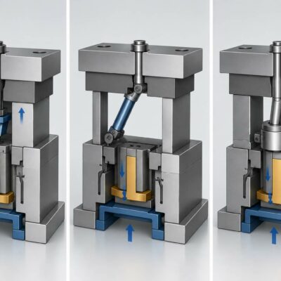
Why thrust force, traction force and friction must all be considered
Choosing a hydraulic cylinder for a locking application inside an injection mold is not simply a matter of calculating the force required to push a slide or wedge into position.
The cylinder may have to perform two different functions:
- generate sufficient force to lock and hold the slide in position;
- generate sufficient force to unlock and retract the slide.
These two requirements are not necessarily equal.
A technical case analyzed by the Vega Team demonstrates why the traction force during the unlocking phase can become the critical parameter, even when the calculated thrust force appears to be sufficient.
1. Start With the Mechanical Load
The first step in selecting a hydraulic cylinder is to understand the mechanical forces acting on the slide or wedge.
In the case analyzed, the calculation was based on:
- two surfaces of 158 cm² each;
- an assumed plastic pressure in the cavity of approximately 350 bar;
- a wedge inclination of 10°;
- an assumed friction coefficient of 0.1.
Based on these parameters, the calculated total thrust force required to hold the wedge/slide in position was approximately:
10,000 kgf.
This calculation provided the initial basis for selecting the hydraulic cylinder.
However, it was not the end of the analysis.
2. Why Thrust Force Alone Is Not Enough
A common mistake when selecting a cylinder for a locking mechanism is to consider only the force required to push the slide into position.
In reality, the cylinder may experience two different operating conditions.
Locking phase
The cylinder must generate sufficient force to keep the slide or wedge in the required position.
Unlocking phase
The cylinder must generate sufficient traction force to overcome the resistance preventing the slide from returning.
These two forces can be significantly different.
In the documented case, the Vega Team identified a possible problem with the traction force of the V260 during the unlocked phase, rather than with its basic thrust capability.
3. Why Is Traction More Difficult to Calculate?
The main difficulty is the effect of friction.
During the unlocking movement, the required force depends on the actual behavior of the mechanical system, including:
- wedge angle;
- contact surfaces;
- applied load;
- friction coefficient;
- lubrication;
- surface condition;
- mold tolerances;
- deformation;
- actual operating conditions.
The Vega Team specifically noted that it was not easy to calculate the friction effect during the traction phase.
This is an important point for mold designers.
A theoretical calculation can provide an excellent starting point, but the actual behavior of the complete mechanism must also be considered.
4. A Cylinder Can Have Enough Thrust but Insufficient Traction
This is one of the most important principles in hydraulic-cylinder selection.
A cylinder can have sufficient force to maintain a slide in position but still be unable to retract it reliably.
The reason is that, in a conventional double-acting cylinder, the effective piston area is different in the two directions.
On the piston side, the hydraulic pressure acts on the full piston area.
On the rod side, the effective area is reduced by the cross-sectional area of the rod.
Therefore, at the same hydraulic pressure:
thrust force is greater than traction force
for a conventional single-rod cylinder.
This difference must be taken into account whenever the cylinder is required to perform both locking and unlocking operations.
5. The Importance of Effective Area
The basic relationship between hydraulic pressure and cylinder force can be expressed as:
Force = Pressure × Effective Area
But the effective area depends on the direction of movement.
For the extension stroke, the effective area corresponds approximately to the full piston area.
For the retraction stroke, the rod area must be subtracted.
This means that selecting a cylinder solely according to its thrust force can lead to an incorrect result when the cylinder must also provide a significant traction force.
For a locking mechanism, both directions therefore need to be checked.
6. The Initial Cylinder Selection
Based on the initial calculation, the Vega Team identified a possible CM100 configuration, to be used at a minimum working pressure of 140 bar.
An alternative was a CR125 configuration, with a minimum working pressure of 100 bar.
The Client was advised to perform its own verification of the application.
This is an important aspect of technical cylinder selection: the manufacturer can perform a preliminary calculation based on the information available, but the final application must be verified against the actual mold design and operating conditions.
7. Why the Calculation Is Based on Assumptions
The initial calculation included several assumed values.
For example:
- approximately 350 bar of plastic pressure;
- a friction coefficient of 0.1;
- a wedge angle of 10°.
These values were explicitly treated as hypothetical in the technical calculation.
This distinction is important.
A calculation based on assumed values should be regarded as a preliminary engineering assessment, not as a guarantee of the actual force required by the completed mold.
If the real friction coefficient or cavity pressure differs significantly from the assumed values, the required cylinder force can also change.
8. The Influence of Friction
Friction can have a substantial influence on the required force.
In the original calculation, the assumed coefficient was:
μ = 0.1.
In an actual mold, however, friction can depend on:
- material combinations;
- surface finish;
- lubrication;
- contact pressure;
- temperature;
- wear;
- contamination;
- maintenance conditions.
For this reason, friction should not be treated as an insignificant secondary parameter.
It can determine whether a cylinder is capable of unlocking the mechanism reliably.
9. The Wedge Effect
The presence of a wedge makes the mechanical calculation more complex.
A relatively small movement of the cylinder can generate a much greater force on the slide because of the inclined geometry.
This is one of the reasons wedges are widely used in mold mechanisms.
However, the same geometry can make the return movement more difficult.
During unlocking, the inclined surfaces can generate additional resistance, particularly when combined with friction.
The cylinder therefore has to be selected according to the complete mechanical system, not just the nominal force acting in one direction.
10. The Unlocking Phase May Be the Critical Phase
The Vega Team specifically identified the unlocking phase as a possible problem with the V260 because of its available traction force.
This provides a useful general rule:
When a hydraulic cylinder is used in a locking mechanism, always verify both the locking force and the unlocking force.
This is particularly important for mechanisms incorporating:
- wedges;
- slides;
- inclined surfaces;
- self-locking geometries;
- high friction;
- large contact forces.
11. A Further Cylinder Evaluation
Following the additional analysis, the Vega Team identified a CF056 as a possible solution, with a minimum working pressure of 160 bar.
Again, the Client was advised to perform its own verification.
This illustrates an important engineering principle: cylinder selection can change after the mechanical behavior of the complete mechanism has been analyzed more carefully.
The first calculation may identify a suitable range of cylinders, while a second analysis of the unlocking phase may require a different solution.
12. Why Can the Cylinder Model Change After the First Calculation?
The selection process can be viewed as:
mechanical load calculation
↓
initial cylinder selection
↓
traction-force analysis
↓
unlocking verification
↓
final cylinder selection
This approach is particularly appropriate when the hydraulic cylinder is integrated into a mechanical mechanism rather than simply performing a straightforward linear movement.
13. Cylinder Selection Is Not Based Only on Bore Diameter
When comparing hydraulic cylinders, the nominal bore diameter is only one parameter.
The designer should also consider:
- effective piston area;
- rod diameter;
- thrust force;
- traction force;
- minimum working pressure;
- maximum working pressure;
- stroke;
- speed;
- mounting configuration;
- available space.
Vega’s current product range includes cylinders specifically intended for cart and plug movement in injection molds, including the V250CE, V400CL, V450CM and V450CP families.
The V400CL, for example, is a compact short-stroke cylinder designed for applications where internal space is extremely limited and is specifically used for moving carts, pins and plugs that can create undercuts in injection molds.
14. Minimum Working Pressure Is an Important Parameter
Another important element in the technical case is that the Vega Team did not simply indicate a cylinder model.
The proposed models were associated with specific minimum working pressures.
The initial calculation indicated:
- CM100 → 140 bar minimum working pressure
- CR125 → 100 bar minimum working pressure
The subsequent evaluation indicated:
- CF056 → 160 bar minimum working pressure.
This demonstrates that the cylinder model and hydraulic pressure must always be considered together.
15. It Is Not Enough to Say “This Cylinder Has Enough Force”
A more technically accurate approach is to establish:
At the available hydraulic pressure, does the selected cylinder provide sufficient force in both directions?
This is particularly important when the cylinder has to:
- lock the slide;
- maintain the slide;
- unlock the slide;
- return the slide to its original position.
The pressure available in the hydraulic system directly affects the force that can be generated.
16. Why the Client Must Verify the Complete Application
In the documented case, the Vega Team explicitly recommended that the Client perform its own verification.
This does not mean that the manufacturer’s calculation is not useful.
On the contrary, the manufacturer can provide:
- preliminary force calculations;
- cylinder recommendations;
- minimum pressure indications;
- technical guidance.
However, the mold designer has access to information that the cylinder manufacturer may not have, including the complete mechanical geometry and actual operating conditions.
The final verification should therefore consider the complete system.
17. The Cylinder Is Only One Part of the Mechanism
The final behavior of the system can depend on:
- slide geometry;
- wedge geometry;
- guide design;
- contact surfaces;
- lubrication;
- friction;
- cavity pressure;
- mold tolerances;
- thermal effects;
- deformation;
- operating conditions.
This is why the cylinder should be considered as one component of a larger mechanical system.
The manufacturer’s cylinder calculation cannot replace verification of the complete mold mechanism.
18. A Practical Procedure for Selecting a Locking Cylinder
For applications involving slides, wedges or locking mechanisms, the following procedure is recommended.
Step 1 – Define the locking force
Determine the force required to keep the slide or wedge in position.
Step 2 – Define the cavity pressure
Use the actual value whenever available. If an estimated value is used, clearly identify it as an assumption.
Step 3 – Define the geometry
Consider:
- contact surfaces;
- wedge angle;
- direction of forces;
- mechanical leverage.
Step 4 – Define friction
Use a realistic coefficient and evaluate how sensitive the calculation is to changes in friction.
Step 5 – Calculate thrust force
Verify that the cylinder can provide the required locking force.
Step 6 – Calculate traction force
Verify the force required to unlock and retract the mechanism.
Step 7 – Consider rod diameter
Remember that the effective area on the rod side is smaller.
Step 8 – Determine minimum hydraulic pressure
Calculate the pressure required to generate the necessary force.
Step 9 – Check the cylinder envelope
Make sure the cylinder fits into the available mold space.
Step 10 – Verify the complete mechanism
The final selection should be checked by the mold designer against the actual application.
19. What Information Should Be Requested From the Client?
When receiving a request for cylinder sizing, it is useful to obtain:
- mold drawing;
- slide or wedge geometry;
- contact surface;
- estimated cavity pressure;
- wedge angle;
- direction of movement;
- required force;
- estimated friction coefficient;
- available hydraulic pressure;
- cylinder stroke;
- available installation space;
- lubrication conditions;
- operating cycle.
In the documented case, the drawing supplied by the Client was used as the basis for the initial force calculation.
20. Always Calculate Both Directions
For a locking application, it is useful to create two separate checks.
Locking verification
Can the cylinder generate enough force to hold the slide in position?
Unlocking verification
Can the cylinder generate enough traction force to release and retract the slide?
The second check can become particularly important when the mechanism includes:
- wedges;
- inclined surfaces;
- self-locking geometries;
- high friction;
- high contact forces.
The technical case analyzed here demonstrates exactly this situation: the potential limitation was not simply the thrust force, but the available traction force during unlocking.
21. Conclusion
Selecting a hydraulic cylinder for locking a slide or wedge inside an injection mold requires more than a simple thrust-force calculation.
In the documented case, the Vega Team calculated a total thrust requirement of approximately 10,000 kgf, based on two 158 cm² surfaces, an assumed cavity pressure of approximately 350 bar, a 10° wedge angle and an assumed friction coefficient of 0.1.
Based on this initial calculation, the CM100, at a minimum working pressure of 140 bar, and the CR125, at 100 bar, were considered as possible solutions.
The subsequent analysis highlighted an even more important issue: the potential limitation was the traction force during the unlocking phase, because the friction effect during traction was difficult to calculate precisely.
A further evaluation led to the consideration of a CF056, with a minimum working pressure of 160 bar.
The main lesson is therefore:
When selecting a hydraulic cylinder for locking a slide or wedge, do not check only the thrust force required to hold the mechanism in position. The traction force required during unlocking must also be verified, taking into account the reduced effective area caused by the rod and the influence of friction.
The correct cylinder is therefore the result of analyzing the complete mechanical system, rather than simply comparing the nominal cylinder force with a single calculated load.
Useful and Verified URLs
For the English article, I would use these official Vega links:
1. Hydraulic Cylinders for Molds
Vega Cylinders – Hydraulic Cylinders for Molds
This is the best general link because Vega specifically categorizes its cylinders for cart and plug movement, ejection plate movement, unscrewing and mechanical locking.
2. Cart and Plug Movement
Vega Cylinders – Cart and Plug Movement
This is particularly relevant to the article because Vega identifies this category for cylinders used to move carts, pins and plugs that can create undercuts in plastic injection molds.
3. V400CL Short-Stroke Hydraulic Cylinders
Vega V400CL – Short-Stroke Hydraulic Cylinders
Useful when discussing compact-cylinder selection and limited installation space. Vega states that the V400CL is mainly used where internal space is extremely limited and that it is used for cart, pin and plug movement in injection molds.
4. Materials and Components
Vega Cylinders – Materials and Components