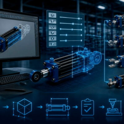
Replacing a hydraulic cylinder in an injection mold is not always as simple as selecting another cylinder with the same bore and stroke.
When a mold has already been designed, machined and assembled, the most important requirement may be compatibility with the existing mechanical and hydraulic interfaces.
The replacement cylinder must fit into the available space, use the existing mounting points, connect to the hydraulic circuit and provide the required stroke and force—ideally without requiring any modification to the mold.
A Vega technical case from 2015 provides a practical example of this situation. A customer had completed a mold and needed hydraulic cylinders similar to the units already specified, but required a solution that could be made interchangeable with the existing cylinders.
1. The Challenge: The Mold Was Already Completed
The customer had just completed an injection mold that was scheduled for delivery within a very short timeframe.
The hydraulic cylinders originally specified for the mold were from another manufacturer and were similar to the type of cylinders used in Vega’s V250 range. The customer wanted an alternative solution that could be installed without redesigning the mold.
The situation was particularly urgent because the original supplier was unable to manage the order at that time due to a company relocation.
The customer therefore needed an alternative source while the mold itself was already approaching completion.
This is a situation that can occur in mold manufacturing:
The mold is ready, but the hydraulic cylinder required for the application is no longer available within the required timeframe.
At this point, modifying the mold may create additional costs and delays.
A more efficient solution may be to develop a cylinder that is compatible with the existing mold interface.
2. What Does “Interchangeable” Really Mean?
When engineers talk about an interchangeable hydraulic cylinder, it is important to distinguish between functional equivalence and mechanical interchangeability.
Two cylinders can have:
- the same bore;
- the same stroke;
- similar hydraulic pressure;
- similar force;
and still not be interchangeable.
For a true replacement, several interfaces must be considered.
Mechanical interface
The replacement cylinder may need to match:
- mounting-hole positions;
- hole spacing;
- mounting dimensions;
- body dimensions;
- rod position;
- overall length;
- rod-end geometry;
- available installation space.
Hydraulic interface
The hydraulic connections may also need to match:
- port position;
- port orientation;
- thread type;
- connection size;
- manifold arrangement;
- available space for fittings and hoses.
Functional interface
Finally, the replacement must provide the required:
- stroke;
- force;
- operating pressure;
- speed;
- movement direction;
- working cycle.
Therefore:
A cylinder can be functionally equivalent without being directly interchangeable.
For an already completed mold, this distinction can be critical.
3. The Customer Did Not Simply Need a Similar Cylinder
The technical request was more specific than simply asking for a cylinder with similar specifications.
The required solution had to have special mounting and oil-supply arrangements interchangeable with the existing cylinders.
This meant that Vega had to adapt the cylinder to the mold’s existing interface.
Instead of asking the mold maker to modify the mold to accommodate a standard Vega cylinder, the approach was to develop a cylinder with the necessary special characteristics.
This is one of the main differences between a:
standard hydraulic cylinder
and a:
custom hydraulic cylinder designed for direct replacement.
4. Why Modifying the Mold Is Not Always the Best Solution
When a replacement cylinder has different mounting dimensions, one possible approach is to modify the mold.
However, this can involve:
- machining new holes;
- modifying mold plates;
- changing mounting locations;
- modifying hydraulic connections;
- creating additional clearance;
- redesigning components;
- repeating dimensional checks;
- extending the project schedule.
Once a mold has already been completed, these modifications can be particularly inconvenient.
In some situations, it is therefore more efficient to adapt the cylinder to the existing mold rather than modify the mold to accommodate the cylinder.
5. Designing a Special Hydraulic Cylinder
In the case analyzed by Vega, the proposed solution included two special cylinders identified as CE063EOEGN150S, with a 150 mm special stroke and special mounting and oil-supply arrangements designed to be interchangeable with the existing cylinders.
A further special cylinder, CE040EOEGN050S, was also proposed with special oil-supply arrangements compatible with the existing cylinder interface.
This demonstrates that customization does not necessarily mean changing the fundamental hydraulic design of a cylinder.
In many cases, customization is primarily about the interface between the cylinder and the machine or mold.
6. The Mechanical Mounting Interface Is Critical
The first area to analyze when replacing an existing cylinder is the mounting system.
The engineering team needs to establish:
- where the cylinder is fixed;
- how the cylinder is positioned;
- where the rod axis is located;
- how much space is available around the body;
- how the cylinder interacts with surrounding mold components.
The mounting interface must be reproduced accurately enough for the new cylinder to occupy the existing position.
Vega’s current hydraulic-cylinder range includes several standard mounting configurations, and the manufacturer states that mounting arrangements can also be customized according to customer requirements.
This makes it possible to determine first whether a standard configuration is suitable and then, if necessary, develop a special version.
7. Hydraulic Connections Are Equally Important
A common mistake when replacing a cylinder is to focus exclusively on the mechanical mounting.
The hydraulic connections must also be compatible.
In the Vega case, the request specifically included special oil-supply arrangements interchangeable with those of the existing cylinders.
This means that the replacement cylinder had to be designed around the existing hydraulic interface.
The following points should therefore be checked:
- port location;
- port orientation;
- thread type;
- port dimensions;
- fitting dimensions;
- hose routing;
- accessibility;
- interference with the mold.
A hydraulic connection is not truly compatible simply because the thread is the same.
The connection must also be physically accessible and installable within the available space.
8. Why a Custom Cylinder Can Be Better Than an Adapter
When a standard cylinder does not match the existing interface, one option is to use adapters.
However, adapters can introduce:
- additional components;
- greater overall dimensions;
- additional connections;
- potential leakage points;
- more complicated installation;
- reduced accessibility;
- possible interference with mold components.
A custom cylinder can sometimes incorporate the required interface directly.
Instead of:
standard cylinder → adapter → existing mold
the solution can become:
custom cylinder → existing mold
This can simplify the installation and reduce the number of interfaces that need to be managed.
9. Stroke Must Also Be Preserved
Mechanical interchangeability is not sufficient if the cylinder does not provide the required movement.
The replacement cylinder must deliver the appropriate stroke for the mold mechanism.
In the Vega case, the proposed CE063EOEGN150S cylinders had a special 150 mm stroke.
The stroke must be checked against:
- starting position;
- final position;
- available installation space;
- core or slide movement;
- mechanical stops;
- required end positions.
A cylinder with insufficient stroke cannot complete the required movement.
A cylinder with excessive stroke can also create problems if mechanical interference is possible.
10. Force Must Remain Compatible
The replacement cylinder must also perform the same mechanical function.
The main parameters to evaluate include:
- bore diameter;
- operating pressure;
- required force;
- return force;
- load;
- movement speed;
- mechanical resistance of the mold mechanism.
The basic hydraulic force relationship is straightforward:
Cylinder force = effective piston area × hydraulic pressure
However, the real application may also involve:
- friction;
- side loads;
- guide resistance;
- acceleration;
- pressure losses;
- mechanical transmission ratios.
Therefore, simply matching the dimensions of an existing cylinder is not enough.
The replacement must also provide the required functional performance.
11. The Time Factor: Standard vs. Special Cylinders
The Vega case also highlights an important practical consideration: customization requires time.
The customer needed the cylinders quickly because the mold was already approaching delivery.
Vega explained that the requested cylinders were special products and therefore could not be supplied immediately within the customer’s required timeframe.
The quotation subsequently indicated:
- 4–5 weeks for the two CE063EOEGN150S cylinders;
- 2 weeks for the CE040EOEGN050S cylinder.
This illustrates an important point for mold designers:
If a non-standard interface is required, the need for a custom cylinder should be identified as early as possible in the mold-design process.
Waiting until the mold is completed can turn a relatively simple customization into a schedule-critical issue.
12. A Temporary Solution for Mold Testing
The customer still needed to test the completed mold.
While waiting for the proposed special cylinders, the customer planned to use cylinders from the original supplier taken from other molds.
This created a distinction between:
temporary equipment for mold testing
and
the final production solution.
This can be a useful project-management strategy when the final hydraulic components have a longer lead time.
Of course, any temporary cylinder must be checked for compatibility with the test conditions before use.
13. Start With the Existing Cylinder Drawing, Not the Catalog
When a customer asks for a replacement cylinder, the most efficient starting point is often the drawing of the existing cylinder.
The engineering team should collect as much information as possible.
Mechanical data
- bore;
- stroke;
- overall dimensions;
- mounting dimensions;
- hole positions;
- rod-end dimensions;
- body geometry.
Hydraulic data
- operating pressure;
- port dimensions;
- port positions;
- thread types;
- oil-supply orientation.
Functional data
- required force;
- speed;
- cycle frequency;
- movement;
- working position.
Environmental data
- operating temperature;
- hydraulic fluid;
- contamination;
- installation conditions;
- available space.
Once these parameters have been collected, the engineer can determine whether an existing standard model is suitable or whether a custom version is required.
14. Standard or Custom?
The next decision is whether the application can be solved with a standard Vega cylinder.
Vega currently offers a broad range of hydraulic cylinders for injection molds and die-casting molds, including the V215CR, V220CC, V250CE, V400CL, V450CM, V450CM-YES, V450CP, V500CZ and other configurations.
A standard cylinder is preferable when:
- mounting dimensions are compatible;
- hydraulic connections are compatible;
- stroke is available;
- bore and force are appropriate;
- overall dimensions fit the mold.
A custom cylinder becomes interesting when:
- the mounting interface is different;
- the hydraulic ports must be repositioned;
- a special stroke is required;
- the installation space is restricted;
- the mold cannot be modified;
- direct interchangeability is required.
Vega explicitly states that its hydraulic cylinders can be customized according to customer requirements.
15. Customization Does Not Mean Compromising Performance
A custom cylinder should not be considered simply as a modified standard product.
The customization process must preserve the required performance of the cylinder while adapting its external interface.
Depending on the application, this can involve:
- special mounting arrangements;
- special oil-supply arrangements;
- custom dimensions;
- special rod configurations;
- different sensor arrangements;
- special materials or seals.
Vega also states that its cylinders can be supplied with special sealing options for applications involving water-glycol or unusually high temperatures.
This means that customization can address both mechanical compatibility and application conditions.
16. Three-Dimensional Compatibility Must Be Checked
A replacement cylinder has to fit not only into the mounting holes but into the complete three-dimensional space available inside the mold.
The engineering review should therefore consider:
- cylinder body;
- rod;
- fittings;
- hoses;
- sensors;
- mold plates;
- moving components;
- mechanical stops.
This is particularly important in compact injection molds, where a few millimeters can determine whether a cylinder can actually be installed.
Vega provides 3D models for its cylinder configurations, making it possible to check external geometry during mold design.
A 3D interference check can prevent a situation in which the cylinder appears dimensionally compatible on paper but cannot actually be assembled.
17. Interchangeability Is a System-Level Requirement
The real objective is not simply to manufacture a cylinder that resembles the original.
The objective is to make the cylinder compatible with the complete existing system.
This means evaluating:
mechanical interface
hydraulic interface
stroke
force
overall dimensions
installation environment
mold function
The 2015 Vega case is a clear example of this approach.
The customer needed a cylinder that could be used in an already completed mold, with special mounting and oil-supply arrangements compatible with the existing units.
The problem was therefore not simply:
“Which standard cylinder is closest?”
It was:
“How can the hydraulic cylinder be engineered so that it fits the existing mold interface?”
18. A Practical Procedure for Replacing an Existing Hydraulic Cylinder
When a mold designer needs to replace an existing cylinder, the following procedure can be used.
Step 1 — Identify the existing cylinder
Record the original manufacturer, model and code if available.
Step 2 — Obtain the technical drawing
The drawing is normally more useful than the product name alone.
Step 3 — Reconstruct the mechanical interface
Measure:
- mounting holes;
- hole spacing;
- body dimensions;
- rod position;
- mounting surfaces;
- overall envelope.
Step 4 — Reconstruct the hydraulic interface
Check:
- port position;
- port orientation;
- thread;
- connection size;
- fitting clearance.
Step 5 — Verify the stroke
Make sure the replacement provides the required movement.
Step 6 — Verify the force
Check bore, pressure and required load.
Step 7 — Check the installation environment
Consider:
- temperature;
- hydraulic fluid;
- available space;
- contamination;
- mechanical loads.
Step 8 — Check the 3D envelope
Verify possible interference with mold components.
Step 9 — Compare standard configurations
Determine whether an existing Vega model can satisfy the requirements.
Step 10 — Develop a custom cylinder if necessary
If the standard configuration cannot reproduce the existing interface, a special cylinder may be the most practical solution.
Step 11 — Validate before production
Review the final drawing and, when available, the 3D model before manufacturing.
19. What This Case Teaches Mold Makers
The most important lesson is straightforward:
Replacing a hydraulic cylinder does not necessarily mean modifying the mold.
When the existing interface is accurately documented, it may be possible to design a replacement cylinder around that interface.
This can preserve:
- mounting positions;
- hydraulic connections;
- stroke;
- functional performance;
- available mold space.
This approach is especially valuable when the mold is already completed and modifying the mold would require additional machining or create production delays.
20. Conclusion
The Vega case demonstrates why replacing a hydraulic cylinder in an existing mold requires more than simply selecting a cylinder with the same bore and stroke.
The customer needed cylinders similar to the existing units, but more importantly required special mounting and oil-supply arrangements that could be used as an interchangeable solution. Vega therefore prepared special configurations, including CE063EOEGN150S cylinders with a 150 mm stroke.
The case also demonstrates the importance of timing. Because these were special cylinders, the required production lead times were longer than those of a standard off-the-shelf configuration.
For mold makers, the most effective strategy is therefore:
identify the existing cylinder → obtain its drawing → analyze the mechanical interface → analyze the hydraulic interface → verify stroke and force → check the 3D envelope → compare standard cylinders → develop a custom version when necessary.
The fundamental principle is:
Instead of modifying a completed mold to fit a new hydraulic cylinder, it can sometimes be more efficient to design the hydraulic cylinder to fit the existing mold.
That is the real value of a custom interchangeable hydraulic cylinder.
Useful Vega Links
- Hydraulic Cylinders for Molds — Vega’s complete range of cylinders for injection molds and die-casting molds, including standard configurations and customizable mounting arrangements.
- Hydraulic Cylinders Catalog — overview of Vega cylinder families and available 3D drawings.
- Custom Hydraulic Cylinders — examples of special hydraulic cylinders developed according to customer requirements.
- V450CM Heavy-Duty Hydraulic Cylinders — useful reference for a compact hydraulic-cylinder family commonly used for mold applications.
- Hydraulic Cylinders for Cart and Plug Movement — Vega cylinders designed for moving carts, pins and plugs in injection molds.
- Hydraulic Cylinders for Ejection Plate Movement — cylinders designed for moving injection-mold ejection plates.