In injection-mold applications, adjusting the preload of a self-locking hydraulic cylinder can require very small and precise mechanical movements.
The cylinder itself may be correctly designed, but the way it is connected to the hydraulic circuit can also influence how easily the final adjustment can be made.
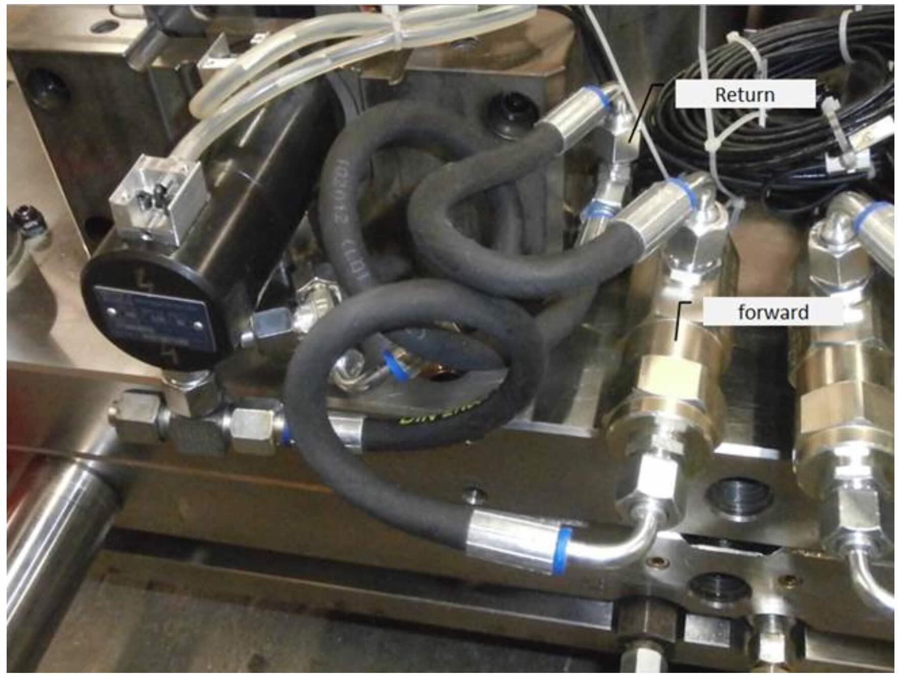
A historical Vega technical case provides a practical example. The Customer initially experienced difficulties adjusting the preload while using rigid hydraulic tubes. The connections were subsequently changed to flexible hoses, and the Customer reported that the preload adjustment was successful. The fine adjustment of the sensors was also completed successfully.
This case highlights an important engineering principle:
The hydraulic connection should not be considered separately from the mechanical adjustment of the cylinder.
What Is Preload in a Self-Locking Hydraulic Cylinder?
Preload is a controlled mechanical compression introduced into the cylinder and the mold mechanism before the injection phase.
Its purpose is to compensate for the elastic deformation that occurs when the mold is subjected to injection forces.
Without adequate preload, even a very small deformation can create a gap between mold components.
This may result in:
- material seepage;
- flash;
- dimensional inconsistencies;
- instability of the mold mechanism.
Vega’s current technical documentation explains that preload is intended to compensate for elastic deformation and maintain stable contact between the mold components during injection.
Preload should therefore be considered an engineering parameter, rather than simply a final mechanical adjustment.
Preload Adjustment Requires Very Small Movements
One of the difficulties in adjusting preload is the extremely small displacement involved.
The Vega Technical Manual points out that, because of the stiffness of steel and the mechanical characteristics of the mold, preload values can involve only a few hundredths of a millimeter.
This explains why the mechanical configuration around the cylinder is important.
When the required adjustment is very small, even mechanical constraints caused by the hydraulic connections can make the operation more difficult.
The objective is not simply to rotate or position the cylinder.
The objective is to achieve a precise and repeatable final position.
A Real Customer Case: Rigid Tubes and Flexible Hoses
In the technical case analyzed by the Vega Team, the Customer reported that the mold adjustments had been successful.
The preload and hydraulic connections had been changed to use flexible hoses, and the fine adjustment of the sensors was also successful.
The Vega Team subsequently noted that the Customer had previously experienced problems adjusting the preload with rigid tubes and had replaced them with flexible ones.
This is an important practical observation.
The case does not mean that flexible hoses are always preferable to rigid tubes.
Rather, it shows that in this particular installation, the flexible connections allowed the Customer to complete the required adjustment successfully.
Why a Rigid Connection Can Make Adjustment More Difficult
A rigid tube has a fixed geometry.
Once connected, it can impose mechanical constraints on the position of the components to which it is attached.
During preload adjustment, this can potentially make it more difficult to:
- rotate the cylinder;
- position the cylinder precisely;
- compensate for small dimensional differences;
- access the required adjustment area;
- avoid mechanical interference.
This becomes particularly relevant when the adjustment itself involves only a few hundredths of a millimeter.
The Vega Technical Manual describes two preload-adjustment systems. With the screw-type flange, for example, the cylinder is rotated clockwise to increase preload and counterclockwise to reduce it, after loosening and subsequently tightening the locking system.
A hydraulic connection that mechanically restricts this movement can therefore make the adjustment more difficult.
Flexible Hoses Can Provide More Freedom During Adjustment
A flexible hose can accommodate movement and changes in orientation much more easily than a rigid tube.
In the Customer case, changing the connections to flexible hoses coincided with successful preload adjustment.
This can be particularly useful during mold commissioning, when the exact final position of a cylinder may need to be adjusted.
However, there is an important qualification.
A flexible hose should not automatically be placed between the cylinder and a check valve when the application requires the valve to be mounted directly on the cylinder.
Vega’s current technical guidance specifically recommends that, where a pilot-operated check valve is required for the application, it should be installed close to—or directly on—the cylinder, and the current preload procedure specifies a rigid connection between the valve and cylinder rather than a hose.
Therefore, the location and function of the hose matter.
Flexible Does Not Automatically Mean Better
The lesson from this case should not be simplified to:
“Always use flexible hoses.”
That would be incorrect.
The correct hydraulic configuration depends on the function of each connection.
Flexible hoses can be advantageous when they provide the freedom required for mechanical adjustment.
Rigid connections can be preferable when:
- the geometry is fixed;
- the connection must remain precisely positioned;
- the check valve must be installed directly on the cylinder;
- hydraulic stability is particularly important;
- the application requires a short connection between the valve and cylinder.
The current Vega technical documentation specifically warns against using a hose between the pilot-operated check valve and the cylinder in the described preload application.
The correct solution therefore requires consideration of the entire hydraulic and mechanical layout.
The Check Valve Must Be Positioned Correctly
The Customer case also contains a clear installation recommendation.
The Vega Team explained that, for correct installation, the check valve should be installed directly on the cylinder using nipples.
If there is insufficient space around the cylinder, the position of the valve can instead be changed and connected using a rigid tube.
This recommendation is important because the check valve is part of the hydraulic load-holding system.
The current Vega support documentation similarly emphasizes that correct check-valve installation, air removal and pressure management are essential for reliable operation.
Preload and Hydraulic Pressure Are Related but Different
It is useful to distinguish two functions.
Preload
Preload establishes the required mechanical compression before injection.
Hydraulic pressure
Hydraulic pressure maintains the operating condition of the self-locking system during the injection phase.
Vega’s current technical documentation specifies maintaining 120 bar push pressure throughout the injection phase for the relevant preload application. If this cannot be maintained, the specified pilot-operated check valve solution is required.
The two functions should therefore not be confused.
Preload establishes the mechanical condition.
Hydraulic pressure maintains the required hydraulic operating condition.
Why Excessive Preload Can Be a Problem
Increasing preload is not always beneficial.
The Vega Technical Manual specifically warns that excessive preload can reduce the allowable locking capacity of the self-locking system.
Current Vega technical documentation also explains that excessive preload can result in:
- increased mechanical stress;
- increased wear;
- unlocking difficulties;
- instability of the locking system.
For this reason, preload should not simply be increased until the mold stops showing a particular symptom.
The adjustment needs to remain within the limits of the selected cylinder and application.
Mold Trials Are Part of the Preload Adjustment
Preload cannot always be established purely from a theoretical calculation.
Vega’s current preload procedure recommends validating the adjustment through actual molding trials. The result should be observed and, where necessary, the preload should be adjusted and the test repeated.
The practical sequence is therefore:
Initial adjustment
↓
Molding trial
↓
Inspect molded parts
↓
Evaluate flash or material seepage
↓
Fine-tune preload
↓
Repeat the test
This approach allows the final preload to be established under the actual operating conditions of the mold.
Sensor Adjustment Comes After Mechanical Adjustment
The Customer case also provides an important detail: after the preload and connections had been successfully modified, fine sensor adjustment was also successful.
This suggests a logical commissioning sequence.
The mechanical position of the cylinder should be established first.
The sensors should then be adjusted to the final cylinder position.
Otherwise, changing the cylinder position after sensor adjustment may require the sensors to be adjusted again.
A practical sequence is therefore:
- Install the cylinder.
- Connect the hydraulic circuit.
- Establish the correct mechanical position.
- Adjust the preload.
- Perform the molding trial.
- Confirm the final cylinder position.
- Fine-tune the sensors.
- Test the complete cycle.
Why Sensor Adjustment Should Be Verified
Hydraulic-cylinder sensors can be sensitive to their position relative to the magnetic or mechanical detection system.
The Vega Technical Manual describes several sensor technologies and also provides a dedicated Switch Tester for checking sensor operation. The tester can check Reed and PNP/NPN sensors and can also be used to check the magnetic ring inside the cylinder.
This can be particularly useful during commissioning and maintenance.
The official Vega accessory range also includes the Switch Tester, controlled check valves and flow regulators.
The Importance of the Fixing Flange
The fixing flange is another important part of the preload system.
The Vega Technical Manual describes two main approaches.
With a solid flange, the cylinder is removed after the first mold trial and the flange is machined according to the required preload. The process may need to be repeated if the preload is not correct.
With a screw-type flange, the cylinder can be rotated to increase or decrease preload without disassembling the cylinder from the mold.
The second approach can therefore make commissioning substantially faster.
This is particularly relevant when several mold trials are required before the final preload is established.
A New Flange Should Be Validated Before Customer Installation
The Customer case also mentioned a new fixing flange.
The Vega Team had three sample pieces available, but before presenting them to the Customer, a validation test was required.
This illustrates an important engineering principle.
A new mechanical component should not be considered ready simply because it has been manufactured.
The component should first be checked for:
- dimensional compatibility;
- mechanical strength;
- correct mounting;
- adjustment range;
- interference;
- practical installation.
Only after validation should it be introduced into the production application.
Avoid Unnecessary Modifications
The final part of the case is also valuable.
After the Customer had changed the connections to flexible hoses and confirmed that the system was working correctly, the Vega Team indicated that no further modifications were necessary.
This is an important principle in technical support.
Once the root problem has been resolved and the system has been successfully validated, additional modifications may create more risk than benefit.
Every additional change can introduce:
- a new leak point;
- a new mechanical interference;
- a different pressure loss;
- another commissioning variable;
- additional maintenance requirements.
A good technical solution is not necessarily the one with the most modifications.
It is the one that solves the problem reliably with the fewest unnecessary changes.
A Practical Installation and Commissioning Procedure
For a self-locking hydraulic cylinder with preload, the following sequence can be useful.
1. Verify the cylinder installation
Check the mounting, alignment and available adjustment space.
2. Install the check valve correctly
Where required, install it directly on the cylinder according to the specified configuration.
3. Plan the hydraulic connections
Determine whether rigid or flexible connections are appropriate for each section of the circuit.
4. Establish the mechanical position
Make sure the cylinder can reach its required final position.
5. Adjust preload
Use the appropriate flange and adjustment procedure.
6. Perform the molding trial
Check the actual behavior of the mold and the molded components.
7. Fine-tune preload if necessary
Make small adjustments rather than increasing preload excessively.
8. Verify the hydraulic pressure
Confirm that the required operating pressure is maintained during injection.
9. Adjust the sensors
Perform final sensor adjustment after the mechanical position is established.
10. Validate the complete system
Run the complete mold cycle and verify mechanical, hydraulic and sensor behavior.
The Main Engineering Lesson
The Customer case is a good example of why hydraulic-cylinder problems should be investigated as system problems.
The cylinder was not necessarily the problem.
The preload adjustment was affected by the way the hydraulic connections were configured. After the Customer changed the connections from rigid tubes to flexible hoses, the preload adjustment was successful and the sensors could also be fine-tuned successfully.
At the same time, the case does not establish a general rule that flexible hoses are always better.
The current Vega documentation shows that, for certain preload applications, the connection between a pilot-operated check valve and the cylinder should remain short and rigid.
Therefore, the correct question is not:
“Should I use rigid or flexible hoses?”
The better question is:
“What type of connection is appropriate for each part of this hydraulic and mechanical system?”
Conclusion
Preload adjustment in a self-locking hydraulic cylinder can involve extremely small mechanical movements, making the surrounding installation surprisingly important.
A historical Vega Customer case showed that difficulties encountered while adjusting preload with rigid hydraulic tubes were resolved after the connections were changed to flexible hoses. The Customer then successfully completed both preload adjustment and sensor fine-tuning.
However, this experience should be interpreted within the context of the complete application.
Flexible hoses can provide useful mechanical freedom during adjustment, but they are not universally preferable. Where a pilot-operated check valve must be installed close to the cylinder, Vega’s current technical guidance specifies a direct rigid connection rather than a hose.
The most reliable approach is therefore to consider:
- cylinder position;
- fixing flange;
- preload;
- check-valve position;
- hydraulic connections;
- pressure stability;
- sensor position;
- mold geometry;
- commissioning procedure.
The key lesson is simple:
Correct preload adjustment depends not only on the cylinder, but also on how the cylinder is installed and connected to the hydraulic circuit.
A well-designed system should make it possible to adjust the preload accurately, validate the result through molding trials and then fine-tune the sensors once the final mechanical position has been established.
Useful and Verified URLs
- How to Correctly Install a Check Valve on a Hydraulic Cylinder in an Injection Mold — Official Vega technical article explaining check-valve installation, air removal and pressure-release requirements.
- Preload in Self-Locking Hydraulic Cylinders — Official Vega article explaining the engineering principles behind preload, elastic deformation and hydraulic conditions during injection.
- Why Hydraulic Cylinder Preload Improves Mold Quality — Official Vega article explaining how preload can help prevent flash and material infiltration and how preload should be validated through molding trials.
- How to Set the Preload on a Vega V270CG Self-Locking Hydraulic Cylinder — Official Vega guide describing the practical preload-adjustment procedure and hydraulic commissioning requirements.
- Hydraulic Cylinders Accessories – Vega Cylinders — Official Vega Cylinders accessories page including controlled check valves, flow regulators, the Switch Tester and other hydraulic-cylinder accessories.
- VR Hydraulic Cylinder Accessories — Official Vega page covering rod accessories, check valves, hydraulic connections and the Switch Tester for checking cylinder sensors.