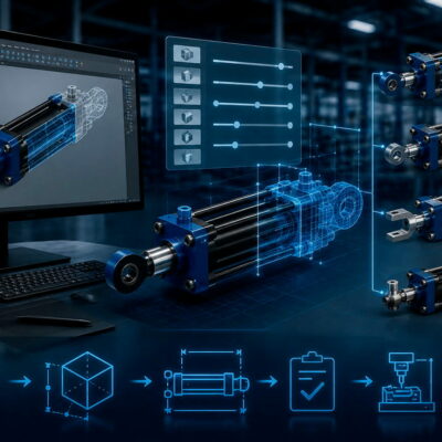
In hydraulic unscrewing systems for plastic injection molds, selecting the correct cylinder is only part of the engineering process.
The rack-and-pinion mechanism must also be evaluated carefully, particularly when a long rack is required.
A Vega technical case illustrates this very well. The Customer requested a special hydraulic-cylinder solution involving both a heavy-duty cylinder for mold movement and a V210CS hydraulic unscrewing cylinder. During the technical evaluation, Vega identified an important mechanical limitation: the length of the rack could create a significant risk of deformation because the available guide was relatively short compared with the rack length.
This is an important lesson for mold designers: when the rack becomes long, the problem is no longer simply one of cylinder stroke. It becomes a question of mechanical stiffness, guidance, alignment and load transmission.
The Application Required Two Different Hydraulic Solutions
The original request included two different cylinder applications.
The first involved two V450CM cylinders with an associated accessory, while the second involved a V210CS unscrewing cylinder with a rack and position sensors.
The two applications had different engineering requirements.
The V450CM cylinders were required to move two slides, while the V210CS was intended to operate an unscrewing mechanism.
This distinction is important because the two cylinders perform fundamentally different functions.
A standard hydraulic cylinder primarily converts hydraulic pressure into linear movement.
An unscrewing cylinder must additionally transmit that linear movement through a rack-and-pinion mechanism to generate rotation.
That additional mechanical transmission introduces another set of design constraints.
Why a Long Rack Can Become a Problem
A rack is not simply an extension of the cylinder.
It is a mechanical transmission component that must remain sufficiently rigid and correctly guided while transmitting force to the pinion.
As its length increases, its resistance to bending becomes increasingly important.
In the case examined by the Vega Team, the proposed rack length was initially 1,000 mm. The technical evaluation identified a concern because the available guide was only approximately 300 mm, making the guide relatively short compared with the rack. Vega therefore warned that the rack could experience deflection during operation.
The Customer subsequently agreed to consider a 950 mm rack instead.
Even with the reduced length, the Vega Team maintained that the relationship between rack length and guide length required careful evaluation.
Rack Length and Guide Length Must Be Considered Together
One of the most important points from this case is that rack length cannot be evaluated independently.
A long rack needs adequate guidance.
If the guided section is relatively short compared with the total rack length, the unsupported portion can become more susceptible to deformation.
The technical correspondence specifically states that the guide length of 300 mm was too short compared with the rack length and that the possible deflection should be evaluated.
This creates a simple engineering relationship:
Longer rack → greater need for effective guidance
The exact allowable configuration depends on the geometry, material, loads, support conditions and operating cycle, so the numbers from this particular case should not be treated as universal design limits.
Why Rack Deflection Matters
A rack that bends or deflects excessively can affect the entire unscrewing mechanism.
Potential consequences include:
- incorrect engagement with the pinion;
- increased mechanical friction;
- uneven load distribution;
- increased wear;
- difficulty maintaining accurate movement;
- additional stress on the rack and guide;
- possible interference during operation.
In an unscrewing application, the rack must transfer the cylinder’s linear force to the pinion efficiently.
If the rack changes its position significantly under load, the geometry of the transmission can change during the working cycle.
That is why rack stiffness is not simply a structural detail.
It can directly affect the performance and reliability of the unscrewing system.
The V210CS Is a Specialized Unscrewing Cylinder
The V210CS is specifically designed for hydraulic unscrewing applications in injection molds.
Vega’s current product documentation lists the V210CS within the Unscrewing cylinder category and describes it as a hydraulic cylinder equipped with an unscrewing device.
The principle is straightforward:
Hydraulic pressure
↓
Linear piston movement
↓
Rack movement
↓
Pinion rotation
↓
Unscrewing of the threaded component
The advantage of integrating the rack with the cylinder is compactness.
Vega’s technical material also describes the V210CS as a compact solution in which the rack-and-pinion mechanism is integrated with the hydraulic cylinder, making it particularly suitable when space inside the mold is limited.
However, the integrated design does not eliminate the need to verify the mechanical transmission.
A Longer Rack Is Not Simply a Longer Stroke
This is perhaps the most important lesson from the case.
It can be tempting to think:
“If the mold requires more movement, we simply need a longer cylinder stroke and a longer rack.”
That approach can be misleading.
The cylinder stroke determines the available linear movement.
The rack must then transmit that movement mechanically.
Increasing the rack length changes the mechanical behavior of the transmission.
The Vega Team therefore evaluated the rack separately from the cylinder itself and highlighted the possible deflection of the long rack.
The result is an important distinction:
Cylinder stroke ≠ automatically acceptable rack length.
The Technical Evaluation Also Considered the V450CM
The V450CM part of the application involved two cylinders moving two slides.
The Vega Team checked the drawing and calculated the forces associated with the proposed configuration.
The calculated thrust force was approximately 4,850 kgf for the two slides, while the calculated traction force was approximately 3,988 kgf for the two slides.
These calculations provided an important basis for confirming the suitability of the proposed V450CM configuration.
This demonstrates another important principle:
Cylinder selection should be based on calculated application loads rather than simply selecting a cylinder from its nominal bore.
The official Vega product range currently identifies the V450CM as a heavy-duty short-stroke compact hydraulic cylinder for mold applications.
A Self-Locking Cylinder Was Not Always Necessary
An interesting part of the technical discussion was the question of whether the application required a self-locking hydraulic cylinder.
The initial discussion involved self-locking cylinders, but after evaluating the application more carefully, the Customer indicated that a self-locking cylinder was not necessary and that the solution had been changed to a V450CM with a check valve.
This is a useful reminder that a technically sophisticated component is not necessarily the best choice for every application.
The correct cylinder should be determined by the actual requirements:
- required force;
- required movement;
- load direction;
- ability to hold the load;
- hydraulic circuit;
- available space;
- safety requirements;
- mechanical configuration.
If a self-locking function is not required, another hydraulic solution may be more appropriate.
Why the 3D Mold Drawing Was Important
The Vega Team initially received a 2D drawing but explained that calculating the relevant surfaces accurately from the 2D information was difficult.
The Team therefore requested the 3D mold drawing to perform a more reliable evaluation.
This is particularly important in complex hydraulic-cylinder applications.
A 2D drawing may show the nominal dimensions, but a 3D model can reveal:
- available installation space;
- interference;
- actual movement;
- rack position;
- guide position;
- mechanical clearances;
- surrounding components;
- possible collision points.
For custom cylinders, the 3D model can therefore be an essential part of the engineering process.
Special Cylinder Design Requires More Than a Catalogue Selection
The V450CM configuration in this application included a specific stroke requirement.
The proposed cylinder was based on a 160 mm standard stroke with an internal stroke reducer to obtain 150 mm of effective stroke.
This is a good example of how a standard cylinder platform can be adapted to a specific mold requirement.
Instead of developing an entirely different cylinder, a standard configuration can sometimes be modified internally to obtain the required working stroke.
This can provide a practical compromise between:
- standardization;
- customization;
- manufacturing efficiency;
- installation requirements.
The Rack Length Was Ultimately Reduced
The original V210CS request specified a 1,000 mm rack.
Following the technical evaluation, the Customer agreed to consider 950 mm instead.
This change may appear relatively small—only 50 mm—but mechanically it can be significant when a component is already close to a deformation limit.
It also illustrates an important engineering strategy:
When a requested dimension creates a mechanical risk, reducing the dimension can sometimes provide a safer and more reliable solution than simply increasing the size of another component.
However, the Vega Team still recommended evaluating the deflection of both rack and guide.
The Customer Could Manufacture the Special Mechanical Component
When a standard Vega rack configuration does not satisfy the mechanical requirements of a particular mold, a customized approach can sometimes be considered.
The current Vega documentation confirms that the V210CS is a specialized unscrewing solution and that customization can be considered for particular applications.
This highlights an important design philosophy:
The hydraulic actuator and the mechanical transmission do not necessarily have to be treated as an indivisible standard package.
Depending on the application, the system can be engineered around:
- a Vega hydraulic cylinder;
- a suitable guide;
- an application-specific rack;
- the appropriate pinion;
- a correctly designed mounting system.
This can make it possible to address applications that fall outside the dimensions of a standard rack.
Do Not Solve Rack Deflection by Guesswork
When a rack becomes unusually long, it is tempting to simply increase its dimensions.
But increasing section size is not the only consideration.
A proper evaluation should consider:
Rack length
Longer racks are generally more sensitive to bending and deflection.
Rack cross-section
The geometry and moment of inertia strongly influence stiffness.
Material
Material properties affect the deformation under load.
Guide length
The guide determines how much of the rack is mechanically supported.
Support position
Where the rack is supported can substantially change the mechanical behavior.
Applied load
The actual force transmitted through the rack must be considered.
Dynamic effects
Acceleration, deceleration and changes in load can increase the mechanical stresses.
Alignment
Even a sufficiently strong rack can experience problems if the rack and pinion are not correctly aligned.
The case therefore demonstrates why a long rack should be evaluated as a mechanical structure, rather than merely as an accessory to the hydraulic cylinder.
Unscrewing Systems Need Integrated Engineering
A hydraulic unscrewing system is made up of several interacting elements:
Cylinder
↓
Rack
↓
Guide
↓
Pinion
↓
Threaded core
↓
Molded component
A problem in one component can affect the entire system.
For example, a cylinder can have sufficient force, but if the rack deflects excessively, the unscrewing system may still fail to perform correctly.
Similarly, a rack can be sufficiently strong, but incorrect alignment between the rack and pinion can create excessive friction or wear.
This is why Vega’s current technical material emphasizes the importance of considering the cylinder and the mechanical transmission as a complete system.
What This Customer Case Teaches Mold Designers
Several practical lessons can be extracted from this technical case.
1. Do not evaluate cylinder stroke alone
The required stroke must be compatible with the mechanical transmission.
2. Check rack deflection
A long rack can become the critical component even when the hydraulic cylinder itself is correctly sized.
3. Consider the guide length
Rack length and guide length must be evaluated together.
4. Use 3D data when possible
Complex mold geometries are much easier to evaluate correctly with a complete 3D model.
5. Calculate the actual forces
The V450CM application was evaluated using calculated thrust and traction forces rather than relying only on nominal cylinder dimensions.
6. Do not automatically choose a self-locking cylinder
If the application does not require self-locking, a standard hydraulic cylinder with an appropriate check-valve solution may be more suitable.
7. Consider special solutions when necessary
A standard cylinder can sometimes be adapted to meet a particular stroke or installation requirement.
Conclusion
This Customer case demonstrates why hydraulic-cylinder selection for injection molds should always be approached as a complete engineering problem.
The application involved two different hydraulic requirements: heavy-duty movement of mold slides using V450CM cylinders and an unscrewing mechanism based on a V210CS cylinder with a long rack.
The most interesting challenge was not the hydraulic force itself, but the mechanical behavior of the long rack.
The original rack length was 1,000 mm, while the available guide was approximately 300 mm. Vega identified the resulting risk of rack deflection and recommended evaluating the application carefully. The rack length was subsequently reduced to 950 mm, although the guide-to-rack relationship still required consideration.
The case also demonstrates the value of obtaining a complete 3D mold drawing, calculating actual cylinder forces and selecting the hydraulic architecture according to the real application rather than simply choosing the most sophisticated cylinder available.
The broader lesson is clear:
In a hydraulic unscrewing system, the cylinder is only one part of the mechanism. Rack length, guide length, stiffness, alignment and pinion engagement can be equally important to the reliability of the final solution.
For long-stroke unscrewing applications, these parameters should therefore be evaluated together from the beginning of the mold design.
Useful and Verified Vega URLs
- Vega Cylinders – Hydraulic Cylinders for Molds — Official product overview, including V450CM and V210CS.
- Designing a Long Rack for a Hydraulic Unscrewing Cylinder — Official Vega technical article specifically addressing long-rack deformation and the V210CS application.
- How to Size a Hydraulic Cylinder for Thread Unscrewing — Official Vega article explaining cylinder sizing, rack-and-pinion transmission and unscrewing applications.
- Unscrewing Devices — Official Vega technical article covering hydraulic unscrewing systems and the V210CS.