From a Real Mold Application to Centralized Sensor Monitoring and Safety
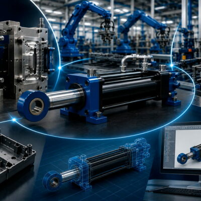
Hydraulic cylinders are widely used in injection molds to control core movements, slides, ejector systems, shut-off mechanisms and other moving components. In many applications, knowing that a hydraulic cylinder has been activated is not enough.
The mold control system must also know where the cylinder is.
A cylinder may need to reach a fully retracted or fully extended position before another operation can safely begin. If the expected position is not reached, or if the control system receives an abnormal combination of signals, the mold may be exposed to incorrect movements, mechanical interference or potentially serious damage.
This is why position sensors and their correct management are an important part of hydraulic mold design.
A real application examined by the Vega Technical Team illustrates this particularly well. During the design of an injection mold, the position of the hydraulic cylinders was changed during the development process. The cylinders had initially been planned for installation in the upper half of the mold, but were subsequently moved to the lower half. The customer provided images showing the intended cylinder arrangement and requested support regarding the final positioning.
The discussion then moved beyond the mechanical positioning of the cylinders.
Vega recommended evaluating the installation of a SIM08 sensor connection and monitoring unit directly on the operator side of the mold. The purpose was to provide centralized management of the individual cylinder sensor signals and make the condition of each sensor immediately visible to the operator.
The application provides an excellent example of how hydraulic-cylinder control can be integrated with sensor monitoring to improve diagnostics, visibility and mold protection.
1. Why position feedback matters in hydraulic molds
A hydraulic cylinder does not operate independently from the mold.
Its movement is normally part of a sequence.
For example:
- A hydraulic valve commands the cylinder to extend.
- The cylinder moves a core or slide.
- A position sensor detects that the cylinder has reached the required position.
- The control system receives the signal.
- The next operation is permitted.
This sequence means that the sensor signal is not simply an indication of cylinder movement.
It can become a condition for the next operation of the mold.
If the sensor signal is missing, incorrect or contradictory, the control system needs to recognize the situation before allowing potentially damaging movements.
This becomes particularly important when several hydraulic cylinders and several sensors are installed on the same mold.
2. The real application: cylinder positioning changed during mold design
The application handled by the Vega Technical Team began with a practical mold-design change.
The customer initially planned to install the hydraulic cylinders in the upper half of the mold.
During the development of the mold, however, the cylinders were moved to the lower half. The customer communicated the new arrangement and provided images showing how the cylinders would be positioned.
The customer subsequently indicated that the cylinder positions would need to be adjusted again before the final installation on the top of the mold and asked for technical support.
This type of change is not unusual during mold design.
The final position of a hydraulic cylinder can be influenced by:
- available space;
- mold architecture;
- accessibility;
- mechanical interference;
- hydraulic hose routing;
- sensor access;
- maintenance requirements;
- movement of other mold components.
But moving the cylinder also affects another important question:
Where and how will its position sensors be connected and monitored?
3. From cylinder positioning to sensor management
The Vega Technical Team did not limit its response to the physical positioning of the cylinders.
It recommended evaluating the installation of the SIM08 directly on the mold, on the operator side, so that the individual sensor signals could be connected and managed from a centralized location.
This is an important design concept.
Instead of treating every sensor as an isolated signal that disappears into the machine wiring, a centralized interface can make the condition of the different sensors immediately visible.
For the operator, this can make troubleshooting considerably easier.
If one cylinder does not reach the expected position, the operator can determine which sensor is reporting the abnormal condition rather than having to investigate every cylinder individually.
4. What happens when several sensors are involved?
Consider a mold containing several hydraulic cylinders.
Each cylinder may have position sensors corresponding to different positions.
Depending on the application, these can indicate conditions such as:
- cylinder retracted;
- cylinder extended;
- mechanism in the expected position;
- mechanism not yet in position.
As the number of hydraulic movements increases, the number of sensor signals increases as well.
Without a clear monitoring system, identifying the source of a fault can become difficult.
An operator may know that the mold has stopped because a required position signal has not been received, but may not immediately know which sensor is responsible.
This is precisely the type of problem that the SIM08 was proposed to address in the application.
5. Centralized monitoring of individual sensor signals
The SIM08 was proposed to connect and manage the signals from the individual sensors.
According to the Technical Team’s communication, the unit allows the operator to see the status of each individual sensor through a series of indicator LEDs.
This provides a simple but valuable diagnostic function.
Instead of relying exclusively on the machine’s general alarm system, the operator can look at the local indicator system and immediately determine which sensor is active or inactive.
In practical terms, the troubleshooting process can become:
Mold stops
↓
Check sensor monitoring unit
↓
Identify sensor with abnormal status
↓
Check corresponding hydraulic cylinder or mold mechanism
This can significantly reduce the time required to locate the source of a problem.
6. Why visual diagnostics are useful on an injection mold
Injection molds can contain a large number of components packed into a relatively small space.
When a hydraulic movement does not occur correctly, the cause may not immediately be obvious.
The problem could be related to:
- the hydraulic cylinder;
- the hydraulic valve;
- the sensor;
- the sensor connection;
- the control signal;
- the mechanical mechanism;
- the mold sequence.
A centralized visual indication does not eliminate the need for technical diagnosis, but it provides an immediate indication of the sensor status.
That distinction is important.
The SIM08 does not simply make the hydraulic cylinder move.
It helps the operator understand what the position sensors are reporting.
7. The operator-side installation is significant
The Technical Team specifically suggested installing the SIM08 on the operator side of the mold.
This is a practical consideration that should not be overlooked.
A diagnostic device is most useful when the operator can access and observe it without unnecessary intervention.
An operator-side installation can make the status indicators immediately visible during:
- mold setup;
- startup;
- production;
- troubleshooting;
- maintenance.
The physical location of the monitoring unit is therefore part of the overall usability of the system.
8. Sensor monitoring is not the same as cylinder control
It is useful to distinguish between two functions.
Hydraulic cylinder control
The hydraulic system controls the movement of the cylinder.
This normally involves hydraulic valves, pressure, flow and the machine control system.
Position feedback
The sensors provide information about the position or state of the cylinder.
The SIM08 sits on the sensor-management side of this system.
Its role in the application was to connect and manage the individual sensor signals and provide a visible indication of their status.
This distinction is important when designing the electrical and hydraulic architecture of a mold.
9. Why sensor status can become a safety condition
A position sensor may provide information that is essential before another mold operation can begin.
For example, a control sequence may require:
Cylinder A retracted
before
Cylinder B extends.
Or:
Core in safe position
before
Mold closes.
If the expected sensor signal is missing, the machine should not simply assume that the mechanical component is in the correct position.
This is why reliable position feedback is an important element of mold protection.
10. The SIM08 includes a protective function
The application described by the Vega Technical Team contains an especially interesting safety feature.
The SIM08 is equipped with a protection device that acts immediately if it detects two signals simultaneously corresponding to the forward and backward positions.
In other words, the system recognizes a contradictory sensor condition.
A cylinder or mechanism should not normally be confirmed as being simultaneously in two opposite positions.
Receiving both signals at the same time can therefore indicate:
- an incorrect sensor condition;
- incorrect wiring;
- an electrical fault;
- a sensor malfunction;
- an abnormal machine command;
- another condition requiring attention.
The important point is that the system does not simply display the signals.
It also uses the contradictory condition as a protective input.
11. Why contradictory position signals are dangerous
Imagine a hydraulic mechanism with two position sensors:
Forward position
and
Backward position.
Under normal operation, the system should transition from one state to the other.
A simplified sequence would be:
Backward sensor ON
↓
Cylinder moves
↓
Backward sensor OFF
↓
Cylinder reaches forward position
↓
Forward sensor ON
The two states should therefore not normally be active simultaneously.
If both signals are detected at the same time, the control system has received information that does not correspond to a normal physical condition.
The SIM08 protection function is designed to react to this situation.
12. Protecting the mold from incorrect movements
The purpose of detecting this abnormal condition is ultimately linked to mold protection.
Injection molds contain many expensive precision components.
A movement performed at the wrong moment can potentially cause mechanical interference between components that are not supposed to occupy the same space at the same time.
The Technical Team explicitly described the SIM08 protection function as a way of safeguarding the integrity of the mold against incorrect operations.
This makes the sensor-management system more than a simple diagnostic accessory.
It becomes part of the overall strategy for preventing incorrect mold movements.
13. Why a sensor fault should be visible immediately
One of the biggest advantages of centralized monitoring is the reduction in diagnostic time.
Without local status indicators, an operator may see only a general machine alarm:
Mold sequence interrupted.
That message does not necessarily identify the source.
With individual sensor indicators, the operator can instead observe the status of each sensor.
The Technical Team specifically highlighted this ability to identify immediately which sensor is presenting an anomaly.
This can make troubleshooting more direct.
14. The connection between mechanical design and diagnostics
The application also demonstrates an important principle in mold engineering:
Changing the physical position of hydraulic cylinders can affect the way their sensors need to be connected and monitored.
The cylinders were moved during mold development.
The sensor-management solution therefore needed to be considered as part of the revised architecture.
This illustrates why hydraulic, mechanical and electrical design should not be treated as completely separate activities.
A change in one area can create consequences in another.
15. Sensor accessibility should be considered during mold design
When designing a mold, engineers often focus on:
- cylinder dimensions;
- stroke;
- force;
- mounting;
- hydraulic connections.
Sensor accessibility can be overlooked.
However, sensors and their connections also need to be considered.
A sensor that is difficult to access can make:
- replacement slower;
- troubleshooting more difficult;
- wiring inspection more complicated;
- maintenance more expensive.
Centralizing the sensor connections in an accessible location can therefore provide practical advantages during the entire life of the mold.
16. From individual sensors to a centralized interface
Without a centralized interface, each sensor signal may be routed separately toward the machine control system.
This can create a more complex wiring architecture.
The SIM08 proposal introduces a centralized point for the sensor connections.
The Technical Team described the unit as allowing the connection and management of the signal from each individual sensor, together with local LED indication.
This makes the relationship between:
sensor → status → diagnostic indication
much easier to understand.
17. The number of connections matters
In the application, the proposed SIM08 configuration included six connectors:
- four supplied as standard;
- two additional connectors.
This is a useful indication of the type of application being considered.
When a mold contains multiple hydraulic cylinders and multiple position sensors, the number of electrical connections can grow quickly.
The monitoring architecture therefore needs to be selected according to the number and type of sensors involved.
18. Why sensor wiring deserves the same attention as hydraulic piping
Hydraulic-cylinder design is normally associated with:
- pressure;
- flow;
- cylinder force;
- speed;
- stroke.
But modern mold systems also depend on the electrical feedback associated with those cylinders.
A hydraulic cylinder can be mechanically perfect and correctly sized, but the overall system can still fail to operate correctly if the position feedback is unreliable.
For this reason, sensor wiring should be treated as part of the complete cylinder application.
19. A sensor is only useful if its signal can be interpreted correctly
The sensor itself is only one element of the system.
The complete chain is:
Mechanical position
↓
Sensor
↓
Electrical signal
↓
Signal management
↓
Machine control
↓
Machine action
A fault anywhere in this chain can affect the final result.
The SIM08 addresses an important part of this chain by providing centralized sensor connection, signal management and visual indication.
20. What this application teaches mold designers
The real application provides several practical lessons.
First: cylinder position can change during mold development
The final hydraulic-cylinder location may differ from the initial concept.
Second: sensor management should be considered at the same time
Moving a cylinder also changes the practical requirements for sensor wiring and accessibility.
Third: diagnostics should be visible
Being able to identify the status of individual sensors can make troubleshooting considerably faster.
Fourth: contradictory signals should be treated as abnormal
A simultaneous forward/backward signal can indicate a condition that requires protection.
Fifth: sensor monitoring can contribute to mold protection
The objective is not only easier troubleshooting, but also preventing incorrect operations that could damage the mold.
21. The difference between an alarm and useful diagnostics
A general machine alarm tells the operator that something is wrong.
Useful diagnostics help explain what is wrong.
This difference can have a significant impact on maintenance.
For example:
Basic alarm
Hydraulic movement not completed.
The operator now needs to investigate.
Individual sensor monitoring
Sensor 4 is not showing the expected state.
The investigation can immediately focus on:
- that sensor;
- its wiring;
- the associated cylinder;
- the corresponding mechanical mechanism.
The SIM08 concept is therefore based on converting sensor signals into immediately visible information for the operator.
22. Why this is particularly valuable in complex injection molds
The larger and more complex the mold becomes, the more important diagnostics can be.
A mold may contain several:
- hydraulic cylinders;
- core pulls;
- slides;
- ejector mechanisms;
- valves;
- position sensors.
When something stops the sequence, identifying the source quickly becomes increasingly important.
A centralized sensor-monitoring system can provide a much clearer overview of the status of the hydraulic mechanisms.
23. The real engineering sequence
The application can therefore be understood as a sequence of practical engineering decisions:
Cylinder arrangement changes
↓
Final cylinder position needs to be established
↓
Sensor connections must follow the hydraulic-cylinder arrangement
↓
Individual sensor signals need to be managed
↓
The operator needs immediate visibility
↓
Contradictory signals must be recognized
↓
The mold must be protected from incorrect movements
This is why the Technical Team proposed the SIM08 as part of the solution rather than treating the sensor wiring as a secondary detail.
24. A centralized sensor system is part of the mold architecture
The most important lesson is perhaps that the sensor-management system should not be considered only after the hydraulic and mechanical design has been completed.
It should be considered during the mold-design stage.
Questions should include:
- How many hydraulic cylinders are installed?
- How many position sensors are required?
- Where are the sensors located?
- Where are the sensor cables routed?
- Can the sensors be accessed?
- Where should the connection unit be installed?
- Can the operator see the sensor status?
- What should happen if contradictory signals are detected?
- How should the mold be protected against an incorrect sequence?
These questions connect the mechanical, hydraulic and electrical sides of the mold.
25. The practical value of the Vega solution
The Technical Team’s recommendation was not simply to add another electrical component to the mold.
The purpose was to create a more controlled relationship between the hydraulic cylinders and their position feedback.
The SIM08 was proposed to provide:
Centralized sensor connection
Individual sensor status indication
Immediate fault identification
Protection against contradictory position signals
Additional protection for the mold
These functions were directly related to the customer’s application and the need to manage the hydraulic-cylinder sensors more effectively.
Conclusion
The application analyzed by the Vega Technical Team began with a relatively normal mold-design problem: the planned position of the hydraulic cylinders changed during the development of the mold.
However, the change in cylinder arrangement highlighted another important engineering requirement: how to connect, monitor and diagnose the position sensors associated with those cylinders.
The proposed solution was to install the SIM08 on the operator side of the mold, providing centralized connection and management of the individual sensor signals together with LED indication of each sensor’s status.
The system also incorporated a protective function capable of reacting when both forward and backward position signals were detected simultaneously, helping protect the mold from incorrect operations.
The broader lesson is important:
Hydraulic-cylinder position sensors should not be treated as simple accessories. They are part of the control and protection architecture of the injection mold.
When several hydraulic movements are involved, knowing the position of each mechanism—and being able to identify an abnormal sensor condition immediately—can make the difference between a simple diagnostic intervention and a potentially damaging mold movement.
SIM08 Architecture, Sensor Diagnostics, Protection Logic and Practical Mold Integration
In Part 1, we followed a real mold application in which the position of the hydraulic cylinders changed during the design phase. The cylinders were initially planned for the upper half of the mold and were subsequently moved to the lower half, requiring the final arrangement and sensor-management strategy to be reconsidered.
The Vega Technical Team recommended evaluating the installation of the SIM08 directly on the operator side of the mold. Its purpose was to connect and manage the signals from the individual sensors while providing immediate visual information about their operating status.
Part 2 looks more closely at how this approach works and why centralized sensor management can be valuable in injection-mold applications.
1. The SIM08 as a centralized sensor interface
The SIM08 is designed as a signal-receiving control unit for multiple types of switches and sensors used with hydraulic cylinders.
The official Vega documentation identifies compatibility with:
- PNP magnetic switches;
- PNP inductive switches;
- Reed switches;
- mechanical switches.
The current Vega product page specifies eight independent M12 inputs and two relay-controlled 0V outputs.
This makes the SIM08 particularly suitable when a mold contains several hydraulic-cylinder sensors that need to be brought together into one accessible monitoring point.
The original application described by the Vega Technical Team followed exactly this philosophy: connect and manage the signal from each individual sensor and make its status immediately visible to the operator.
2. Why eight independent inputs are useful
A hydraulic cylinder can have more than one position signal.
For example, a cylinder may require detection of:
- retracted position;
- extended position.
When several cylinders are installed in the same mold, the number of individual signals can quickly increase.
A centralized box with multiple independent inputs avoids having to treat every sensor as a completely separate diagnostic problem.
The current SIM08 configuration provides eight independent M12 inputs, making it possible to organize multiple sensor signals around a single connection point.
The exact number of sensors required for a particular mold still depends on its architecture and sensor configuration; the available source does not specify the exact sensor count for the customer’s mold in the application discussed.
3. Local LED indication
One of the most useful functions described in the original Technical Team communication is the possibility of seeing the status of each individual sensor through LED indicators.
This provides immediate local feedback.
Instead of requiring the operator to determine the sensor condition from a remote PLC screen or from a general machine alarm, the SIM08 provides a direct indication at the sensor-management unit.
The official Vega product documentation similarly explains that each input has a signaling LED, allowing the operator to check the functioning of individual switches and identify anomalies more quickly.
4. From a general alarm to a specific diagnosis
Consider a mold containing several hydraulic cylinders.
Suppose one movement does not complete.
A conventional machine alarm might simply indicate:
Hydraulic movement not completed.
The operator then has to determine which cylinder or sensor is responsible.
With individual sensor indication, the diagnostic sequence can be much more direct:
Cycle interrupted
↓
Check SIM08
↓
Identify the sensor with the unexpected status
↓
Inspect the corresponding cylinder or mechanism
This does not eliminate the need for troubleshooting, but it can significantly reduce the time required to identify where the investigation should begin.
This is exactly the practical advantage highlighted by Vega’s Technical Team when proposing the SIM08 for the application.
5. Why the sensor signal is important
A position sensor does not simply tell the operator that a cylinder exists.
It provides information about the state of a mechanical movement.
For example:
Cylinder retracted → sensor signal
or
Cylinder extended → sensor signal
The machine control system can then use that information as part of its sequence.
This creates a chain:
Mechanical position
→
Sensor
→
Electrical signal
→
Signal management
→
Machine control
→
Next operation
The reliability of the entire sequence therefore depends partly on the quality and correct management of the position feedback.
6. Forward and backward signals
The SIM08 application described by Vega is particularly interesting because the system manages two position-related signal series.
The Technical Team specifically described a protection function that intervenes if it detects two signals simultaneously corresponding to the forward and backward positions.
This is an abnormal condition.
A mechanism cannot normally be confirmed as being simultaneously at both ends of its travel.
The detection of both conditions therefore provides an indication that something in the sensor or control system requires attention.
7. Why simultaneous signals are treated as an abnormal condition
Consider a simplified hydraulic-cylinder sequence.
At the beginning:
Backward position = active
The cylinder receives the command to move.
During movement:
Backward position = no longer active
The cylinder continues moving.
At the end:
Forward position = active
The two position states therefore represent different stages of the movement.
If both signals remain active simultaneously, the system is receiving contradictory information.
The source material does not identify a single specific cause for such a condition. It simply establishes that the SIM08 protection logic recognizes the simultaneous active condition and acts to prevent subsequent mold-cycle steps.
That distinction is important: the system detects the abnormal signal combination; diagnosing its physical cause still requires checking the relevant sensor, wiring and mechanical system.
8. Protection of the mold
The purpose of this protection function is not merely to display an electrical anomaly.
The Technical Team explicitly stated that the function helps protect the integrity of the mold from incorrect operations.
This is particularly important because hydraulic movements in an injection mold are often interdependent.
A mechanism may need to be in a known position before another operation is permitted.
If that position information is incorrect, allowing the next step to proceed could create an unwanted mechanical interaction.
The SIM08 therefore introduces an additional layer of protection based on the sensor signals.
9. The importance of preventing the next cycle step
The official Vega documentation describes the same principle: when two switches in the relevant series remain active, the SIM08 stops the following stages of the molding cycle from proceeding, helping prevent damage to the mold’s mechanical components.
This is an important distinction.
The system is not simply saying:
“There is an alarm.”
It is also preventing the sequence from continuing under a condition that the system considers abnormal.
That makes the sensor-management unit relevant to both diagnostics and mold protection.
10. No special software is required
Another practical characteristic of the SIM08 is that it does not require special software for configuration.
The official Vega documentation states that the unit can be configured through DIP switches located under the cover, rather than requiring the type of software configuration associated with BUS-based systems.
This can be advantageous in a mold environment where the objective is often to have a robust and easily understandable control system.
A technician does not necessarily need a laptop or dedicated programming environment simply to configure the sensor-management box.
11. Manual actuation and sensor checking
The SIM08 also allows individual switches in the series to be manually actuated through the integrated switch controls.
According to Vega’s documentation, this allows the technician to check the functioning of individual switches while observing the corresponding LED indication.
This is particularly useful during:
- mold commissioning;
- maintenance;
- troubleshooting;
- sensor replacement;
- electrical checks.
It allows the technician to distinguish between a problem with the sensor signal and a problem further downstream in the machine-control system.
12. Sensor testing when the cylinder is already installed
Vega also offers a separate Hydraulic Cylinders Switch Tester.
The official documentation explains that testing sensors can otherwise require moving the cylinder rod, which can be inconvenient when the cylinder is already installed in the mold. The tester can be connected to Reed or PNP/NPN sensors and uses LEDs to indicate when the switch is triggered.
This is an important complementary tool.
The SIM08 is intended for installed sensor signal management during operation, while the tester is intended to facilitate sensor checking during maintenance and troubleshooting.
These are related but different functions.
13. Sensor technology and cylinder construction
The type of sensor used also depends on the hydraulic-cylinder design.
For example, Vega explains that the V450CM has an all-steel body, making magnetic sensors unsuitable for detecting the cylinder position in that configuration. Vega therefore uses mechanical switches for those applications.
The official Italian product information describes several mechanical-switch configurations and states that they are compatible with the SIM08 Connection Box.
This demonstrates why sensor selection should be made together with cylinder selection.
The sensor is not an isolated electrical component; its technology has to be compatible with the construction and operating conditions of the cylinder.
14. Mechanical switches for compact cylinders
Vega’s mechanical switches are designed specifically for hydraulic-cylinder applications.
The V450CM mechanical-switch options include configurations designed to minimize the additional space required around the cylinder.
The official documentation states that some versions can operate at temperatures up to 180°C, while the standard versions are specified for lower temperatures. It also states that the switches can be used for up to ten million cycles, with an exception for the MS6 180°C configuration.
These specifications are useful when designing a mold because sensor selection must consider:
- available space;
- temperature;
- expected number of cycles;
- accessibility;
- connection method.
15. The importance of temperature
A sensor-management box installed directly on a mold must also be protected from excessive temperature.
The current SIM08 documentation specifies:
- IP67 protection
- maximum working temperature around 80°C.
This means that the SIM08 should not simply be mounted wherever there is physical space.
If the mounting location is exposed to excessive heat, Vega recommends using an insulating plate to keep the temperature within the specified limits.
This is an important practical consideration when integrating the box directly onto a mold.
16. Why operator-side installation makes sense
The original application specifically proposed positioning the SIM08 on the operator side of the mold.
This is logical because the box provides diagnostic information.
The operator needs to be able to see:
- which sensor is active;
- which sensor is inactive;
- whether an abnormal condition is present.
A diagnostic device that is difficult to see or access loses much of its practical value.
The SIM08 is therefore not merely an electrical junction point; its location should be considered from the perspective of machine operation and maintenance.
17. The five-meter main cable
The official SIM08 documentation specifies a main connector with a 5-meter multipolar cable, allowing the unit to be installed close to the mold and simplifying the cable-connection work.
This is particularly relevant for injection molds because the electrical control cabinet may not be immediately adjacent to the mold.
A dedicated local sensor-management point can reduce the complexity of routing individual sensor connections over longer distances.
18. Installation beside the mold
The SIM08 is specifically designed to be installed right beside the mold, according to Vega’s official product documentation.
This creates a practical architecture:
Hydraulic cylinders
↓
Position sensors
↓
SIM08 beside the mold
↓
Main cable
↓
Machine control system
This arrangement keeps the individual sensor connections concentrated around the mold rather than requiring every sensor cable to be routed independently toward the machine.
19. Protection against the mold environment
The mold environment can be demanding.
There may be:
- high temperatures;
- dust;
- dirt;
- mechanical movement;
- risk of collision;
- limited space.
The SIM08 has IP67 protection, but Vega also specifies installation precautions for particularly aggressive environments.
Where there is a risk of collision or significant exposure to dust and dirt, Vega recommends installing the unit inside a protective metal enclosure with a transparent polycarbonate front panel.
This allows the LEDs to remain visible while protecting the electronics.
20. Sensor management as part of mold maintenance
The value of a sensor-management system becomes particularly clear during maintenance.
Imagine a mold that stops because one hydraulic movement has not been confirmed.
Without individual sensor indication, the technician may need to:
- inspect the PLC;
- trace the wiring;
- test individual sensors;
- move the cylinder;
- inspect connectors.
With local LED indication, the first diagnostic step can be much simpler:
Look at the sensor status.
If the expected sensor does not illuminate, the technician immediately has a starting point for the investigation.
The SIM08 therefore contributes to reducing diagnostic time, which was one of the specific reasons for its proposal in the original customer application.
21. The relationship between sensor monitoring and production downtime
A mold stopped by a sensor fault can interrupt production even when the hydraulic cylinder itself is mechanically healthy.
For example, the cylinder may physically reach the required position, but if the corresponding sensor signal is not correctly detected, the machine may not allow the next stage of the sequence to proceed.
The production problem is therefore not necessarily a hydraulic-cylinder failure.
It may be a position-feedback problem.
This is why having immediate information about individual sensor status is valuable.
22. The importance of distinguishing hydraulic and electrical faults
When a hydraulic movement fails, there are at least two broad categories of possible problems:
Hydraulic/mechanical
- insufficient pressure;
- insufficient flow;
- mechanical obstruction;
- cylinder problem;
- valve problem.
Electrical/sensor-related
- sensor not triggered;
- damaged cable;
- incorrect connection;
- sensor failure;
- contradictory sensor signals.
A centralized sensor-management system helps the technician determine whether the position feedback is behaving as expected before beginning a more extensive hydraulic investigation.
23. The SIM08 does not replace the machine PLC
The SIM08 should not be interpreted as a replacement for the machine’s complete control system.
Its function is more specific:
- receive sensor signals;
- manage the sensor series;
- provide local indication;
- detect the defined abnormal condition;
- prevent subsequent operations when the protection condition occurs.
The machine’s overall sequence control remains part of the broader molding-machine architecture.
The SIM08 therefore acts as a dedicated sensor-management and protection interface within that architecture.
24. Why this is relevant when redesigning a mold
The real application started because the physical arrangement of the hydraulic cylinders changed during mold development.
This is a useful reminder for mold designers.
When a cylinder is moved, engineers should not only check:
- mechanical clearance;
- mounting;
- stroke;
- hydraulic hose routing.
They should also check:
- sensor location;
- cable routing;
- accessibility;
- sensor-management architecture;
- protection logic.
A mechanical redesign can therefore require an electrical redesign as well.
25. A practical design sequence
For a mold using several hydraulic cylinders with position sensors, a useful design sequence is:
Step 1 – Define the hydraulic movements
Identify which mechanisms require hydraulic actuation.
Step 2 – Define the required position feedback
Determine which positions need to be monitored.
Step 3 – Select compatible sensors
Consider cylinder construction, temperature, space and cycle requirements.
Step 4 – Plan the sensor wiring
Determine where each sensor cable will terminate.
Step 5 – Select the sensor-management architecture
Consider whether a centralized unit such as SIM08 is appropriate.
Step 6 – Define the protection logic
Determine which contradictory or abnormal states must prevent the next operation.
Step 7 – Choose the installation position
Place the monitoring unit where it is accessible and protected.
Step 8 – Test the complete system
Verify the sensors, wiring, indicators and protection logic before production.
26. The configuration described in the real application
The original Vega communication proposed a SIM08 configuration with six connectors: four supplied as standard and two additional connectors.
This detail is useful because it shows that the recommendation was not simply theoretical.
The Technical Team was considering the actual sensor-management requirements of the mold and proposing a concrete configuration.
The objective was to give the customer a practical solution for connecting and monitoring the individual sensor signals.
27. Why centralized monitoring can improve troubleshooting
The main advantage can be summarized in one concept:
Visibility.
Without centralized monitoring, a sensor fault may be hidden inside the machine’s wiring architecture.
With a local sensor-management unit:
Sensor status → visible indication
The operator can immediately see whether the relevant input is active.
This does not automatically identify every possible mechanical or electrical fault, but it makes the first diagnostic step significantly clearer.
28. The broader engineering lesson
The application illustrates a principle that extends beyond the SIM08 itself.
In a modern injection mold, the hydraulic cylinder is not an isolated component.
It is part of an integrated system involving:
Mechanical movement
Hydraulic actuation
Position sensing
Electrical signal management
Machine sequence control
Mold protection
A reliable mold requires all of these elements to work together.
Conclusion
The real application examined by the Vega Technical Team began with a change in the physical arrangement of hydraulic cylinders during mold development. The cylinders were moved between the mold halves, requiring the final configuration and sensor-management strategy to be reconsidered.
Vega recommended evaluating the SIM08 on the operator side of the mold to connect and manage the signals from the individual sensors and provide immediate visual indication of their status.
The current official SIM08 documentation confirms that the unit provides eight M12 sensor inputs, LED indication, compatibility with several sensor technologies, IP67 protection and a maximum working temperature around 80°C.
Its protection function is particularly important: when the defined abnormal condition involving simultaneous forward and backward signals occurs, the system prevents subsequent stages of the molding cycle from proceeding, helping protect the mold from incorrect movements.
The key lesson is therefore broader than the product itself:
Position sensors are an integral part of hydraulic-cylinder applications in injection molds.
When several hydraulic movements are involved, the ability to see the status of each sensor, identify abnormal signals and prevent an unsafe sequence can significantly improve diagnostics and contribute to protecting the mold.
Useful and verified Vega URLs
- SIM08 Connection Box – official Vega product page — the most relevant page for this article. It covers the SIM08 inputs, M12 connectors, LEDs, sensor compatibility, protection function, IP67 rating and temperature limits.
- Hydraulic Cylinder Accessories – official Vega page — includes the SIM08, sensor tester, valves and other accessories.
- Hydraulic Cylinders – official Vega product range — useful for connecting the article to Vega’s complete hydraulic-cylinder range.
- Mechanical Switches for Hydraulic Cylinders – official Vega page — useful for explaining the relationship between cylinder-mounted mechanical switches and the SIM08.
- Hydraulic Cylinder Accessories and Switch Tester – official Vega page — useful for the maintenance and sensor-testing section.