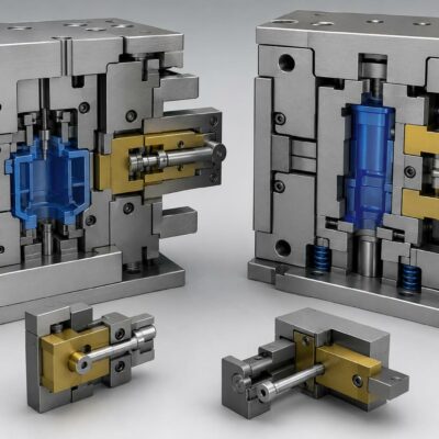
Stroke Design, Mechanical Stops, Sensor Selection and Misalignment Compensation
Hydraulic cylinders used in injection molds are often treated as relatively simple actuators: select the required force, define the stroke, install the cylinder and connect the hydraulic circuit.
In practice, the integration of a cylinder into the mold can be considerably more demanding.
The available space, required stroke, mechanical end stop, sensor technology, cylinder mounting and alignment between moving plates all have to be considered together.
A real mold application examined by the Vega Technical Team illustrates this very well. The application involved a 2+1 cavity mold with hydraulic cylinders installed on the third plate. During the design phase, the customer asked whether the cylinder rod could be shortened by 5 mm so that the third plate itself would determine the mechanical end position while still maintaining the required 130 mm stroke.
The technical discussion subsequently involved the choice between a cylinder with magnetic sensors and a V450CM configuration with mechanical micro-switches, as well as the possibility of recessing the rod into the third plate and using hammer-head connections to compensate for potential misalignment during movement.
This application demonstrates an important principle:
The hydraulic cylinder should be designed together with the mold mechanism, rather than treated as an independent component.
1. The application: cylinders installed on the third plate
The mold considered in the application was a 2+1 cavity mold, with hydraulic cylinders associated with the third plate.
The customer sent the mold configuration to the Technical Team and requested confirmation regarding the possibility of modifying the cylinder rod length.
The request was specific:
- shorten the rod by 5 mm;
- maintain a required stroke of 130 mm;
- avoid reducing the effective movement to 125 mm;
- use the closing of the third plate as the mechanical end stop.
At first sight, removing 5 mm from the end of a cylinder rod may appear to be a relatively minor modification.
However, the Technical Team did not approve shortening the rod.
Instead, an alternative was proposed:
The rod could potentially be recessed into the third plate.
This distinction is technically important.
2. Why shortening a cylinder rod is not necessarily a simple modification
A hydraulic cylinder is designed as a complete assembly.
The rod length is related to:
- the cylinder’s overall geometry;
- available stroke;
- mounting arrangement;
- mechanical travel;
- position of the end components;
- relationship between the cylinder and the mold plates.
Removing material from the end of the rod changes the original geometry.
In this application, the Technical Team therefore did not recommend simply cutting 5 mm from the rod. Instead, the available space in the third plate could potentially be used to accommodate the existing rod length.
This is a useful design principle:
When a cylinder appears to be too long for the available space, modifying the cylinder is not necessarily the first solution to consider.
The mold itself may provide a possibility for accommodating the component without changing the cylinder’s original construction.
3. Maintaining 130 mm instead of 125 mm
The customer’s requirement was particularly precise.
The available geometry had led to a concern that the effective stroke could become 125 mm instead of the required 130 mm.
The customer therefore asked whether 5 mm could be removed from the rod so that the closing of the third plate could act as the final mechanical stop while maintaining the required 130 mm movement.
This illustrates why stroke should always be considered together with the actual mold geometry.
The nominal stroke printed on a cylinder specification is not necessarily the same thing as the usable movement available in the assembled mold.
The final result depends on:
- cylinder mounting;
- rod geometry;
- plate geometry;
- mechanical stops;
- available clearance.
4. Mechanical end stops and hydraulic-cylinder stroke
A hydraulic cylinder can generate movement, but the mold designer still needs to determine how that movement is physically limited.
In this application, the customer wanted the closing of the third plate to determine the end position.
This creates an important distinction between:
Cylinder stroke
The movement that the hydraulic cylinder is capable of providing.
Mechanical end position
The position actually reached by the mold mechanism.
These two concepts are related but should not automatically be assumed to be identical.
The mechanical design of the mold determines how the cylinder’s movement is transferred to the moving plate.
5. Why the third plate can influence cylinder integration
A three-plate mold has a more complex moving architecture than a simple two-plate arrangement.
The cylinder is not operating in isolation.
It is mechanically connected to a plate that must move relative to the other mold components.
The relationship between:
cylinder → rod → third plate → mold mechanism
must therefore be considered when determining:
- stroke;
- mounting position;
- end position;
- clearance;
- sensor location.
The real application demonstrates this directly because the desired cylinder stroke and the closing position of the third plate were being considered together.
6. Recessing the rod instead of shortening it
The alternative suggested by the Technical Team was to recess the rod into the third plate, rather than shorten the rod by 5 mm.
This is an important mechanical-design solution.
Instead of changing the cylinder:
Original approach
Cylinder rod → too much available length → cut 5 mm
the proposed approach was:
Alternative
Cylinder rod → retained → accommodate part of its length within the third plate
The second solution preserves the original cylinder geometry while adapting the mold to the component.
7. Why preserving the original cylinder geometry can be advantageous
A standard cylinder configuration has been designed and manufactured with specific dimensional relationships.
Unnecessary modifications can introduce additional variables.
When possible, maintaining the original cylinder configuration can simplify:
- replacement;
- spare-parts management;
- future maintenance;
- dimensional control;
- repeatability.
In this particular application, the Technical Team therefore recommended considering a modification to the third plate, rather than shortening the cylinder rod.
The source does not provide a detailed structural calculation for the proposed recess, so the article should not infer dimensions or safety margins that are not documented.
8. The importance of alignment
The application also raised another important issue: alignment during movement.
The Technical Team recommended considering a connection using hammer heads because of the dimensions of the plate and the possibility of misalignment or sticking during movement.
This is a significant detail.
A hydraulic cylinder produces linear movement along its axis.
The mold mechanism, however, may experience slight geometric deviations during assembly and operation.
If the connection between the cylinder and moving plate is completely rigid, even a small misalignment can potentially create unwanted side loads or resistance to movement.
9. Why misalignment matters for hydraulic cylinders
A hydraulic cylinder is primarily designed to apply force along its axis.
The ideal load condition is therefore:
Cylinder axis → load direction
If the mechanism introduces an angular deviation, the connection can experience forces that are not perfectly aligned with the cylinder axis.
This can lead to:
- increased friction;
- sticking;
- uneven loading;
- additional wear;
- difficulty during movement.
The source specifically mentions the possibility of disalignments / impuntamenti—misalignment or sticking—and recommends evaluating hammer-head connections to address this issue.
10. Hammer-head connections as a compensation solution
The Technical Team recommended evaluating hammer-head connections because of the dimensions of the plate and the possibility of misalignment during movement.
The important engineering principle is that the connection should accommodate the actual mechanical conditions of the mold.
Instead of assuming that every component will remain perfectly aligned throughout its movement, the connection can be designed with appropriate freedom to accommodate small deviations.
This can help avoid a situation in which the cylinder itself becomes responsible for compensating for a misaligned mold mechanism.
11. The cylinder should not be forced to compensate for mold misalignment
A hydraulic cylinder should ideally drive the mechanism without being subjected to unnecessary lateral forces.
When a plate or moving component is not perfectly aligned with the cylinder axis, the connection should be designed appropriately.
This is particularly relevant for large plates.
The Technical Team specifically referred to the dimensions of the plate when recommending consideration of hammer-head connections.
This suggests that the geometry of the moving plate was an important factor in determining the appropriate connection method.
12. Sensor selection became part of the same design discussion
The application did not involve only mechanical integration.
The customer was also considering the possibility of using cylinders with magnetic sensors and had entered a cylinder configuration with a magnetic sensor in the design.
The Technical Team instead suggested considering V450CM cylinders with mechanical micro-switches as an alternative to the V220 series.
This is an important aspect of the case.
The choice of cylinder was being evaluated together with the choice of sensor technology.
13. Magnetic sensors versus mechanical micro-switches
The source confirms that the application considered both:
- cylinders with magnetic sensors;
- V450CM cylinders equipped with mechanical micro-switches.
The Technical Team recommended the V450CM with mechanical micro-switches as an alternative to the V220.
The source does not provide a detailed comparison of the two sensor technologies for this particular mold, so it would be incorrect to attribute a specific technical advantage to magnetic or mechanical sensors beyond what is explicitly documented.
The important point is that sensor selection was part of the cylinder-selection process.
14. Why sensor choice should be made during cylinder selection
A position sensor is not an independent accessory that can always be added later without considering the cylinder.
The selected cylinder needs to accommodate the appropriate sensor configuration.
In this application, the customer had already incorporated a cylinder configuration with magnetic sensors, while Vega proposed evaluating the V450CM with mechanical micro-switches.
This demonstrates the importance of discussing sensor requirements during the cylinder-selection phase.
15. The V450CM as an alternative
The Technical Team recommended the V450CM with mechanical micro-switches as an alternative to the V220 series.
This was not simply a change of model number.
The cylinder selection had to be considered in relation to the actual mold architecture.
Relevant questions included:
- required stroke;
- available space;
- rod geometry;
- position of the third plate;
- end position;
- sensor configuration;
- connection to the moving plate.
The real application demonstrates why cylinder selection should be based on the complete mechanical and functional requirements of the mold.
16. The role of the third plate in determining the final geometry
The third plate was central to the application because it represented both:
- the moving component associated with the cylinder;
- the potential mechanical end position.
The customer wanted the closing of the third plate to provide the end stop while maintaining the required 130 mm cylinder movement.
The Technical Team’s response was therefore not simply:
“Use a shorter cylinder.”
Instead, the recommendation was to consider how the existing cylinder geometry could be integrated into the plate by recessing the rod.
17. Mechanical integration is a system problem
This case demonstrates that several apparently independent parameters are actually connected:
Cylinder stroke
affects
plate movement
which affects
mechanical end position
which affects
rod geometry
which affects
available space
which affects
mounting and connection design
At the same time:
sensor technology
affects
cylinder configuration
and
position feedback.
The result is a system in which mechanical, hydraulic and electrical requirements have to be considered together.
18. What happens if the cylinder is too long?
When a cylinder appears too long for the available mold space, several possible solutions may exist.
Depending on the application, the designer could investigate:
- different cylinder geometry;
- different mounting arrangement;
- recessing part of the rod into the plate;
- changing the connection;
- changing the mechanical stop.
But these solutions are not interchangeable.
In this application, Vega specifically rejected shortening the rod by 5 mm and suggested evaluating a recess in the third plate instead.
This should therefore be presented as the solution proposed for this specific application, rather than as a universal rule.
19. Why the end stop must be clearly defined
A hydraulic cylinder can reach a position because:
- the cylinder reaches the end of its available stroke;
- a mechanical component stops the movement;
- the control system removes the hydraulic command;
- a combination of these conditions occurs.
In the application discussed here, the customer wanted the closing of the third plate to define the end position.
This makes the mechanical geometry of the mold particularly important.
The designer must know precisely where the plate stops relative to the cylinder’s available movement.
20. Why 5 mm can matter
Five millimetres may appear insignificant when looking at a large mold.
But in a precision mold, 5 mm can determine whether:
- the cylinder reaches the required position;
- the plate reaches its intended stop;
- the desired 130 mm movement is achieved;
- another component interferes;
- the cylinder requires modification.
The customer’s request was specifically motivated by the difference between 130 mm and 125 mm of effective movement.
This illustrates how small dimensional differences can become important in mold engineering.
21. The danger of solving a clearance problem by modifying the cylinder
When space is limited, it may be tempting to modify whichever component appears easiest to change.
For example:
“There is 5 mm too much rod length, so remove 5 mm from the rod.”
But the correct question is:
Which component should be modified to achieve the required geometry while preserving the intended cylinder configuration?
In this case, the Technical Team suggested modifying the way the rod was accommodated in the third plate rather than shortening the rod itself.
This is a useful approach to component integration.
22. The importance of the 3D mold model
The customer provided a 3D mold design and requested confirmation regarding the proposed cylinder arrangement and modification.
The Technical Team also requested the modified 3D model before continuing the evaluation.
This highlights the importance of working with the actual mold geometry.
A cylinder cannot be correctly evaluated only from a catalogue drawing when:
- the plate geometry is complex;
- space is limited;
- the rod interacts directly with a moving plate;
- alignment is critical.
The 3D model provides the necessary context for evaluating the complete assembly.
23. The importance of iterative design
The communication between the customer and Vega shows an iterative design process.
The customer provided the mold arrangement.
↓
A dimensional requirement was identified.
↓
The possibility of modifying the cylinder was discussed.
↓
Vega proposed an alternative involving the third plate.
↓
The connection method was also reconsidered because of potential misalignment.
↓
The cylinder and sensor configuration was evaluated.
This is a typical example of how specialized cylinder manufacturers can contribute to mold design beyond simply supplying a standard component.
24. Cylinder selection should start with the mold mechanism
A common mistake is to select a cylinder first and then try to adapt the mold around it.
For specialized applications, the process can be more effective in the opposite direction.
Start with:
What must the mold mechanism do?
Then define:
- required movement;
- required force;
- available space;
- end position;
- connection;
- sensor feedback.
Only then select the cylinder configuration.
The application analyzed here follows this logic: the customer’s mold geometry and movement requirements drove the discussion about cylinder type, rod geometry and sensor configuration.
25. The importance of the connection between rod and plate
The connection between the cylinder rod and the third plate deserves particular attention.
It transfers the cylinder force to the moving mold component.
If the connection is too rigid for the actual geometry, small alignment errors can become problematic.
If it is appropriately designed to accommodate the expected conditions, the mechanism can move more smoothly.
The Technical Team’s recommendation to evaluate hammer-head connections was specifically linked to the dimensions of the plate and the possibility of misalignment or sticking.
26. A practical design checklist
For hydraulic cylinders installed on a moving mold plate, the designer should verify:
Cylinder
- required stroke;
- required force;
- overall dimensions;
- rod length;
- sensor configuration.
Mold
- plate thickness;
- available space;
- movement;
- mechanical stop;
- clearance.
Connection
- alignment;
- possibility of angular deviation;
- risk of sticking;
- connection geometry.
Sensor
- technology;
- position;
- accessibility;
- compatibility with the cylinder.
Final assembly
- actual 3D geometry;
- complete travel;
- end position;
- maintenance access.
The real application touched virtually all of these areas.
27. The main engineering lesson
The most important lesson from this application is that a hydraulic cylinder cannot be specified independently from the mold architecture.
A 5 mm dimensional difference can affect the achievable stroke.
A plate geometry can determine whether the rod needs to be recessed.
A large moving plate can introduce alignment considerations.
The desired position feedback can influence the cylinder and sensor configuration.
These are not separate engineering decisions.
They form one integrated design problem.
Conclusion
The real application analyzed by the Vega Technical Team involved a 2+1 cavity injection mold with hydraulic cylinders installed on the third plate. The customer needed to maintain a 130 mm movement while using the closing of the third plate as the mechanical end position, and therefore asked whether the cylinder rod could be shortened by 5 mm.
Vega did not recommend shortening the rod. Instead, the Technical Team indicated that the rod could potentially be recessed into the third plate, preserving the cylinder geometry while adapting the mold to the available space.
The Technical Team also recommended evaluating hammer-head connections because of the dimensions of the plate and the possibility of misalignment or sticking during movement.
At the same time, the cylinder and sensor configuration was reconsidered. The customer had evaluated a cylinder equipped with magnetic sensors, while Vega proposed considering the V450CM with mechanical micro-switches as an alternative to the V220 series.
The broader lesson is clear:
In an injection mold, cylinder stroke, rod geometry, mechanical stops, mounting connections and position sensors must be designed as one integrated system.
A cylinder that fits dimensionally is not necessarily a cylinder that is correctly integrated into the mold. The final solution must consider how the cylinder moves the plate, where the movement stops, how alignment is maintained and how the cylinder’s position is detected.
Mechanical Integration, Stroke Management, Sensor Configuration and Practical Design Considerations
In Part 1, we examined a real application involving a 2+1 cavity injection mold with hydraulic cylinders installed on the third plate.
The customer needed to maintain a 130 mm movement, while using the closing of the third plate as the mechanical end position. The initial proposal considered shortening the cylinder rod by 5 mm, but the Vega Technical Team indicated that shortening the rod was not the preferred solution. Instead, the rod could potentially be recessed into the third plate.
The same application also raised questions about the connection between the cylinder and the moving plate. Because of the dimensions of the plate and the possibility of misalignment or sticking, the Technical Team recommended evaluating hammer-head connections.
Finally, the cylinder and sensor configuration had to be considered. The customer had evaluated a V220 configuration with magnetic sensors, while Vega proposed the V450CM with mechanical micro-switches as an alternative.
Part 2 examines the engineering principles behind these decisions.
1. The cylinder is only one component of the complete mechanism
When a hydraulic cylinder is installed in an injection mold, its performance depends on the surrounding mechanical architecture.
The complete system includes:
- hydraulic cylinder;
- cylinder rod;
- rod-end connection;
- moving plate;
- guides;
- mechanical stops;
- sensors;
- hydraulic circuit;
- control system.
The cylinder generates the hydraulic force, but the mold mechanism determines how that force is transmitted and where the movement ultimately stops.
This is why selecting a cylinder purely according to bore and stroke can be insufficient.
Vega’s own engineering material emphasizes that cylinder selection should consider more than force and stroke, including installation dimensions and the actual mechanical conditions of the mold.
2. Nominal stroke versus usable mold movement
One of the most important distinctions in this application is the difference between the nominal cylinder stroke and the actual movement available in the assembled mold.
A cylinder may have a specified stroke, but the mold designer must still determine:
- where the cylinder starts;
- where the rod connects;
- where the moving plate starts;
- where the mechanical stop is located;
- whether any part of the rod is accommodated inside the plate.
In the application discussed here, the customer specifically wanted to obtain 130 mm of effective movement, rather than approximately 125 mm, while using the third plate as the end stop.
This makes the geometry of the complete assembly more important than the cylinder catalogue specification alone.
3. Why five millimetres can become an engineering problem
In a large mold, 5 mm may appear insignificant.
In a precision mechanism, however, 5 mm can determine whether the required movement is achieved.
A 5 mm difference can influence:
- final plate position;
- mechanical clearance;
- sensor activation;
- available cylinder travel;
- interference between components;
- mechanical end-stop position.
The customer’s request to remove 5 mm from the rod therefore had a direct relationship with the required 130 mm movement.
The important lesson is that small dimensional differences should be evaluated within the complete kinematic chain of the mold.
4. Why shortening the rod was not the preferred solution
The Technical Team indicated that the rod could not simply be shortened by 5 mm. Instead, it suggested evaluating whether the rod could be recessed into the third plate.
This approach has a clear engineering logic.
Rather than modifying the cylinder itself:
Cylinder geometry remains unchanged
while
the mold geometry accommodates the rod.
This can preserve the original cylinder configuration and avoid introducing an unnecessary modification to a manufactured component.
The exact dimensions and structural requirements of the recess must, of course, be verified on the actual mold design. The available case material does not provide a structural calculation for the proposed recess.
5. Recessing the rod into the third plate
A recess in the moving plate can provide additional installation space without changing the external length of the cylinder rod.
Conceptually:
Without recess
Cylinder → Rod → Plate
With recess
Cylinder → Rod → Recessed area in plate
This approach can be particularly useful when the required movement is already defined and the available installation space is limited.
However, the recess must be evaluated together with:
- plate thickness;
- structural requirements;
- connection geometry;
- clearance;
- rod movement;
- surrounding components.
It should therefore be treated as a mold-design modification, not simply as a dimensional adjustment.
6. The mechanical stop must be defined precisely
The customer wanted the closing of the third plate to determine the final position.
This means that the mechanical stop becomes an important part of the cylinder application.
The designer needs to understand the relationship between:
Cylinder stroke
→
Rod movement
→
Third-plate movement
→
Mechanical stop
The cylinder should not be selected without considering this chain.
7. Hydraulic stroke does not automatically define the mold’s final position
A common design assumption is:
“The cylinder has a 130 mm stroke, therefore the plate will move 130 mm.”
That conclusion is not necessarily correct.
The actual plate movement depends on the mechanical connection and the geometry of the complete mechanism.
For example, the effective movement may be influenced by:
- rod-end geometry;
- mounting position;
- mechanical stops;
- recesses;
- linkages;
- plate travel.
This is why the 3D mold assembly is particularly important in applications such as the one discussed here.
8. The 3D model is part of the engineering process
The customer provided the mold design and the Technical Team requested the modified 3D model during the evaluation.
This is significant.
A catalogue drawing can establish the cylinder’s nominal dimensions, but it cannot fully demonstrate how the cylinder interacts with:
- the third plate;
- adjacent components;
- guides;
- mechanical stops;
- sensors;
- connection hardware.
For complex applications, the cylinder must therefore be evaluated inside the actual mold assembly.
9. Alignment becomes more important with large moving plates
The Technical Team also highlighted a potential issue with misalignment or sticking and recommended evaluating hammer-head connections because of the dimensions of the plate.
This is an important consideration.
A large plate may be guided at several points, but small dimensional deviations can still occur.
If the cylinder rod is rigidly connected to the plate and the cylinder axis is not perfectly aligned with the actual movement, the cylinder can be exposed to additional mechanical loading.
10. The ideal cylinder load is axial
Hydraulic cylinders are primarily intended to generate force along their axis.
The ideal situation is therefore:
Cylinder axis
↓
Rod axis
↓
Direction of load
↓
Direction of movement
When these directions coincide, the cylinder is operating under the intended type of loading.
When they do not, additional forces may be introduced.
This is why the connection between the cylinder rod and the moving plate deserves as much attention as the cylinder itself.
11. What misalignment can cause
The case material specifically refers to the possibility of disalignment and sticking and recommends considering a suitable connection to compensate for these conditions.
In general engineering terms, unwanted misalignment can contribute to:
- increased friction;
- irregular movement;
- increased mechanical stress;
- premature wear;
- higher resistance during movement.
The purpose of an appropriate rod-end connection is therefore not simply to transmit force.
It can also help the mechanical system tolerate the real conditions of the mold.
12. Hammer-head connections
For this particular application, Vega recommended evaluating hammer-head connections because of the dimensions of the plate and the possibility of misalignment or sticking.
The important principle is that the connection should be compatible with the actual kinematics of the moving plate.
The article should not assume a specific degree of angular compensation or a specific allowable misalignment because those values are not given in the source material.
The correct approach is to evaluate the complete mechanical assembly and select the appropriate connection based on the actual geometry.
13. Why a rigid connection is not always the best connection
A rigid connection can appear attractive because it is simple.
However, simplicity does not automatically mean that it is the best solution.
If the moving plate has even a small deviation from the cylinder axis, a completely rigid connection may transmit that deviation directly to the cylinder.
An appropriately designed connection can instead help accommodate the mechanical realities of the assembly.
This is particularly relevant when:
- the plate is large;
- several guides are involved;
- the cylinder is mounted away from the center of the plate;
- multiple cylinders operate together.
14. Multiple cylinders increase the importance of alignment
The application concerns cylinders installed on a third plate.
When more than one cylinder moves the same plate, another consideration appears:
the cylinders must work together mechanically.
Even if both cylinders have identical nominal strokes, the plate may experience unwanted loading if:
- one cylinder moves differently;
- the guides have different friction;
- the mechanical connections are not aligned;
- one side of the plate reaches the stop earlier.
Vega’s technical material on simultaneous hydraulic cylinders highlights synchronization, force distribution, guide friction and structural deformation as factors that must be considered when multiple cylinders operate on the same component.
15. Cylinder synchronization and mechanical guidance
Hydraulic synchronization should not be confused with mechanical guidance.
The hydraulic circuit controls the cylinder movements, but the mold’s guide system determines how the moving plate is physically constrained.
If the plate is correctly guided, the cylinders can focus on generating the required movement.
If the cylinders are expected to compensate for poor guidance, the system may become unnecessarily stressed.
This is why the hydraulic and mechanical design should be considered together.
16. The importance of the cylinder body and installation dimensions
The V450CM is part of Vega’s Heavy Duty Block Cylinder range. The official product documentation identifies the V450CM as a compact, heavy-duty cylinder available in different bore and stroke configurations.
The official product range also lists V450CM among the hydraulic-cylinder families specifically intended for plastic injection molding and die-casting applications.
This is relevant because the application was not simply looking for any hydraulic actuator.
The cylinder needed to fit a particular mold architecture while providing the required movement and sensor configuration.
17. V220CC and magnetic sensors
The customer had also considered a V220 configuration with a magnetic sensor, specifically a configuration including an MSU4 magnetic switch.
Vega’s current official documentation confirms that the V220CC range is available in configurations prepared for magnetic switches and that the MSU4 is used with the corresponding V220CC configuration.
This provides a useful comparison with the alternative proposed by the Technical Team.
18. V450CM with mechanical micro-switches
The Technical Team proposed considering the V450CM equipped with mechanical micro-switches as an alternative to the V220 series.
The choice of sensor technology must always be related to the construction of the specific cylinder.
Vega’s product documentation shows that mechanical switches are available for applications involving the V450CM. The official V450CM range includes different configurations, while Vega’s broader sensor documentation explains the available sensor technologies for its hydraulic cylinders.
19. Sensor selection is part of the mechanical design
A position sensor is often considered an electrical component.
In a mold, however, its location is fundamentally mechanical.
The sensor must be:
- physically mounted;
- accessible;
- protected;
- positioned relative to the moving rod;
- compatible with the cylinder;
- connected to the machine control system.
Therefore, the choice between magnetic and mechanical sensing should be considered at the same time as the cylinder configuration.
This was exactly what happened in the application discussed here.
20. Why sensor accessibility matters
A sensor that works correctly during the first test is not necessarily a well-designed solution if it becomes difficult to access during maintenance.
The designer should consider:
- Can the sensor be replaced?
- Can its cable or connector be accessed?
- Can the sensor status be checked?
- Is it protected from mechanical damage?
- Is there sufficient space for maintenance?
These considerations become particularly important in compact injection molds.
21. Sensor configuration and mold control
The sensor provides information about the cylinder’s position.
The machine can then use this information to determine whether the next operation is permitted.
A simplified sequence could be:
Cylinder moves
↓
Sensor detects position
↓
Position confirmed
↓
Next mold operation permitted
If the expected position is not detected, the machine can prevent the sequence from progressing.
This is why the sensor should be considered part of the complete mold-control architecture rather than simply an accessory.
22. The relationship between the mechanical stop and the sensor
There is another important point in this application.
The third plate was intended to provide the mechanical end position.
The sensor, however, provides the electrical confirmation of position.
These are two different functions.
Mechanical stop
Physically determines where the moving component stops.
Position sensor
Provides information to the control system about the position.
The two systems should work together rather than being confused with one another.
23. Mechanical stop versus hydraulic pressure
A hydraulic cylinder should not automatically be considered the best component for absorbing every mechanical impact at the end of travel.
The actual end-of-stroke behavior depends on:
- moving mass;
- speed;
- hydraulic pressure;
- flow;
- mechanical stop;
- cushioning;
- mold structure.
Vega’s technical material on hydraulic cushioning emphasizes that end-of-stroke energy management becomes important when moving masses operate at higher speeds.
Therefore, if the third plate is intended to provide the mechanical end position, the complete motion and stopping conditions should be evaluated rather than considering only the nominal stroke.
24. Mechanical stopping and hydraulic cushioning are different functions
This distinction is particularly important.
A mechanical stop determines the physical limit of movement.
A hydraulic cushioning system can manage the energy associated with stopping the moving mass.
They should not automatically be treated as interchangeable.
The case material does not specify a cushioning requirement for this particular mold, so no conclusion should be drawn that the application requires hydraulic cushioning.
However, if the plate moves at high speed or has significant mass, end-of-stroke dynamics should be considered during the engineering review.
25. The importance of the complete 3D assembly
The Technical Team’s request for the modified 3D model is particularly relevant here.
A 3D assembly allows the designer to verify:
- rod clearance;
- plate thickness;
- recess depth;
- sensor position;
- connection geometry;
- guide alignment;
- mechanical stops;
- surrounding components.
This is much more reliable than evaluating each component separately.
26. A practical engineering workflow
For applications similar to this one, a useful workflow is:
Step 1 – Define the required movement
Determine the actual movement required by the mold mechanism.
Step 2 – Define the mechanical end position
Determine where the moving plate must stop.
Step 3 – Select the cylinder
Choose bore, stroke and configuration based on the actual application.
Step 4 – Verify the rod geometry
Check whether the rod can be accommodated within the available mold space.
Step 5 – Check the connection
Evaluate alignment and potential sticking.
Step 6 – Select the sensor technology
Determine whether magnetic, mechanical or another sensor configuration is appropriate.
Step 7 – Integrate the sensor
Verify accessibility and protection.
Step 8 – Verify the complete 3D assembly
Check all clearances and movement conditions.
Step 9 – Test the complete system
Verify movement, end position and sensor feedback.
27. Why changing the mold can be better than modifying the cylinder
The solution proposed in this application illustrates a broader principle.
When there is a dimensional conflict between a standard cylinder and the mold, there are two general approaches:
Modify the cylinder
or
Modify the mold interface.
The Technical Team recommended evaluating the second approach by recessing the rod into the third plate rather than shortening the rod.
This can be a useful design philosophy when the cylinder is already available in a suitable standard configuration.
However, whether the mold can safely accommodate such a recess must always be determined from the actual plate design.
28. Standard components versus customized solutions
Injection molds frequently require customized mechanical interfaces.
That does not necessarily mean that the hydraulic cylinder itself should be extensively modified.
A more efficient strategy can sometimes be:
Standard hydraulic cylinder
custom mold interface
This preserves the cylinder configuration while adapting the surrounding mold structure to the application.
The real application is an example of this philosophy.
29. Why the V450CM was considered
The V450CM belongs to Vega’s compact heavy-duty block-cylinder family. The official product documentation describes the series as compact and heavy duty, with different bore and stroke options.
The application therefore involved more than selecting a cylinder based on nominal dimensions.
The Technical Team was considering:
- cylinder architecture;
- mechanical integration;
- rod geometry;
- sensor technology;
- plate movement;
- connection method.
This is the correct level of analysis for a complex mold application.
30. The broader lesson for mold designers
This application demonstrates why hydraulic-cylinder selection should take place before the mold geometry is completely frozen.
If the cylinder is selected too late, the designer may discover that:
- the rod is too long;
- the sensor is inaccessible;
- the mechanical stop is in the wrong position;
- the connection creates misalignment;
- the required stroke is not available;
- the cylinder cannot be mounted in the intended space.
The earlier the hydraulic-cylinder configuration is integrated into the 3D mold design, the easier it is to avoid these conflicts.
31. A cylinder should be evaluated in its real operating environment
The official Vega documentation itself warns that its 3D models and drawings represent the external interface and should not be used to infer internal dimensions.
This is another reason why the complete application should be reviewed with the manufacturer when the design involves tight dimensional constraints.
For this particular application, the interaction between the rod and the third plate was sufficiently important that the modified 3D model was requested for evaluation.
32. What this real application teaches
The case can be summarized through five engineering principles.
1. Do not modify the cylinder unnecessarily
The proposed solution was to recess the rod rather than shorten it.
2. Define the actual mechanical end position
The customer wanted the third plate to determine the final position.
3. Consider alignment
The Technical Team recommended evaluating hammer-head connections because of possible misalignment and sticking.
4. Select the sensor together with the cylinder
The application compared magnetic-sensor and mechanical-switch configurations.
5. Validate the complete 3D assembly
The modified mold geometry needed to be reviewed before finalizing the solution.
Conclusion
The application of hydraulic cylinders to a three-plate injection mold is an excellent example of why cylinder selection cannot be separated from mold design.
The customer needed a specific 130 mm movement and wanted the third plate to provide the mechanical end position. The initial idea of shortening the rod by 5 mm was not recommended; instead, Vega proposed evaluating a recess in the third plate to accommodate the existing rod geometry.
Because of the dimensions of the moving plate and the possibility of misalignment or sticking, the Technical Team also recommended evaluating hammer-head connections.
At the same time, sensor selection was considered as part of the cylinder solution. The customer had evaluated a V220 configuration with magnetic sensing, while Vega proposed the V450CM with mechanical micro-switches as an alternative.
The broader engineering lesson is clear:
The correct hydraulic cylinder is not simply the one with the right bore and stroke. It is the cylinder that can be correctly integrated into the complete mechanical, hydraulic and electrical architecture of the mold.
For three-plate molds in particular, the designer should evaluate stroke, rod geometry, mechanical stops, plate movement, alignment, connection type and sensor configuration together.
Please read the next part of this article HERE!
Useful and verified URLs
I checked the current official Vega pages and selected links that are directly relevant to this article.
- V450CM – Official Vega product page — technical information on the V450CM heavy-duty block cylinder and available configurations.
- V220CC – Official Vega product page — useful for the comparison with the V220CC configuration and MSU4 magnetic sensors.
- Vega Hydraulic Cylinders – Product Range — official overview of Vega’s hydraulic-cylinder families for injection molding and die casting.
- Vega Materials and Components — useful for technical information on cylinder construction, materials, seals and component selection.
- Vega Official Blog – Hydraulic Cylinder Sizing — useful additional technical reading on selecting cylinders according to the real application.
- Vega Official Blog – Simultaneous Hydraulic Cylinders — relevant to alignment, synchronization, guide friction and force distribution when multiple cylinders move the same mold component.
- Vega Official Blog – Hydraulic Cushioning — useful for the relationship between moving masses, end-of-stroke behavior and hydraulic cushioning.