

In injection molding, hydraulic cylinders are frequently used to actuate slides, cores, wedges and other mold mechanisms that must remain securely in position during the injection phase. When the moving element is exposed to high cavity pressure, however, the cylinder is not simply required to generate enough force to move the mechanism.
It must also resist the force generated by the injection pressure without allowing the slide or core to move backward.
This distinction is particularly important when using a self-locking hydraulic cylinder. In this type of application, the cylinder performs two different functions:
- it generates the hydraulic force required to move or position the mold mechanism;
- once the mechanism reaches its working position, the locking system must resist the external load generated during injection.
The correct cylinder therefore cannot be selected simply by comparing its nominal hydraulic force with the expected load. The designer must consider the actual geometry of the mold, the surfaces exposed to plastic pressure, the direction of the resulting force, the mechanical transmission system and, where applicable, the effect of preload.
1.1 The actual load is determined by the mold geometry
One of the most important aspects emerging from Vega’s technical dimensioning cases is that the effective surface exposed to pressure must be determined from the actual geometry of the molded component and the mold mechanism.
For example, in one Vega calculation, the effective frontal surface was approximately 100 cm². With an estimated cavity pressure of 500 bar, the resulting thrust force was calculated as approximately 50,000 kgf. When a lower cavity pressure of 350 bar was considered, the calculated force was approximately 35,000 kgf.
This illustrates a fundamental engineering principle:
where:
- = force generated by the pressure;
- = effective projected area subjected to the pressure;
- = pressure acting on that area.
However, this equation must be applied to the correct effective area. Using an arbitrary geometric dimension, the projected area of the entire component, or an underestimated contact area can lead to a substantial undersizing of the hydraulic cylinder.
A real Vega case illustrates this problem particularly well. In an application involving two CM063 cylinders, the original design had considered a surface of approximately 5 cm², while a subsequent analysis indicated that the relevant surface was actually approximately 9.2 cm². The cylinders were retracting during molding, and the hydraulic circuit and fluid compressibility were also identified as factors requiring investigation.
Therefore, the first step in professional cylinder dimensioning is not selecting the cylinder.
It is identifying the correct load-producing surface.
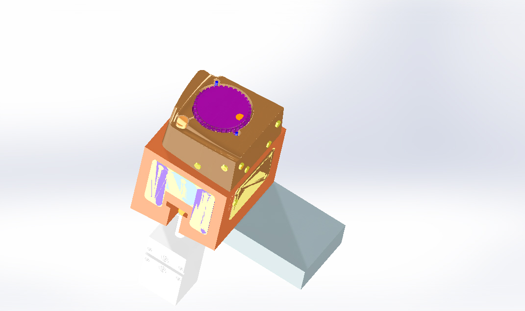
1.2 Injection pressure does not act directly on the cylinder
Another important point is that the cavity pressure does not necessarily act directly along the cylinder axis.
The force generated inside the mold may be transferred through:
- slides;
- wedges;
- inclined planes;
- cores;
- ejector plates;
- mechanical stops;
- locking elements.
Consequently, the hydraulic cylinder may be subjected to a load that is different from the simple product of cavity pressure and molded-part area.
This is why Vega’s technical evaluations frequently distinguish between different mechanical configurations.
In one application, for example, Vega considered a solution using a cylinder directly on the axis of the slide and, alternatively, a solution in which the cylinder operated through an inclined slide mechanism. For the direct configuration, a CF030 was calculated as sufficient at a minimum working pressure of 100–130 bar, while the alternative inclined-plane configuration led to the recommendation of a CM063 at a minimum working pressure of 110 bar.
The mechanical architecture of the mold therefore becomes part of the hydraulic-cylinder calculation.
1.3 Direct actuation versus wedge actuation
A particularly important distinction is between a cylinder acting directly on the moving element and a cylinder operating through a wedge.
In a direct configuration, the cylinder force is transferred substantially along the same axis as the required movement.
In a wedge configuration, the relationship between cylinder force and slide force depends on the geometry of the inclined surfaces.
This can produce a significant mechanical advantage, but it also introduces additional considerations such as:
- wedge angle;
- direction of the forces;
- friction;
- contact pressure;
- mechanical efficiency;
- lateral loads;
- stresses in the wedge and slide;
- required locking force.
Vega’s technical documentation contains applications where the cylinder was specifically selected to operate the wedge rather than directly carry the entire mold load. In one case, a CM050 or CM063 was considered sufficient for holding and moving the wedge, while a substantially larger CF084 was considered when a single cylinder was positioned directly on the slide axis.
This is an important practical lesson:
The same mold load can require substantially different cylinder configurations depending on how the force is mechanically transmitted.
The cylinder should therefore be dimensioned as part of the complete mechanical system, not as an isolated hydraulic component.
1.4 Why the 3D mold geometry matters
For complex applications, a two-dimensional description is often insufficient to determine the correct cylinder size.
Vega’s technical department explicitly requested the 3D geometry of the plastic parts in order to verify the surfaces involved in the force calculation.
This is particularly relevant when the mechanism involves:
- undercuts;
- deep cores;
- slides;
- inclined surfaces;
- threaded components;
- multiple moving elements;
- asymmetric pressure areas.
The engineer must determine not only how much surface exists, but also which surface contributes to the force acting against the hydraulic mechanism.
A correct calculation therefore begins with the mold geometry and proceeds toward the hydraulic cylinder selection—not the other way around.
The engineering sequence
A reliable dimensioning procedure can consequently be summarized as:
3D mold geometry → effective pressure area → resulting mold force → mechanical transmission → required cylinder force → hydraulic pressure → cylinder selection → locking/preload verification
This sequence will be developed in the following sections, including the distinction between thrust force, traction force, useful force and locking force, which is essential when selecting a self-locking cylinder for an injection mold.
Force Calculation, Preload and Locking Performance
The first step in sizing a self-locking hydraulic cylinder is to determine the force generated by the injection pressure. However, this is only the beginning of the calculation.
For an injection-mold application, the engineer must distinguish between injection thrust, extraction force, cylinder force, locking force and preload. These forces do not necessarily act in the same direction and they are not interchangeable.
The Vega technical documentation provides several practical examples showing how these parameters are evaluated.
2.1 Calculating the injection thrust force
The basic relationship remains:
where:
- = resulting force;
- = effective projected area;
- = pressure acting on that area.
A Vega calculation for a slide, for example, considered an effective surface of approximately 12.9 cm² and an estimated cavity pressure of 500 bar, resulting in a total thrust force of approximately 6,450 kgf.
For another slide in the same technical evaluation, the effective surface was approximately 10.5 cm². At the same estimated 500 bar cavity pressure, the resulting thrust was approximately 5,124 kgf.
These examples demonstrate why the actual projected surface must be established before selecting the cylinder.
A relatively small change in effective area can produce a substantial change in the required retaining force when injection pressure is high.
2.2 Thrust force is not the same as extraction force
A common design error is to calculate only the force generated during injection.
A slide or core may experience a very different force when it has to be pulled out of the molded component.
Vega technical calculations distinguish between:
Injection thrust
The force generated by the pressure acting on the projected surface of the mold component.
Extraction or traction force
The force required to separate the core, slide or plug from the molded plastic.
These two forces can be calculated using completely different parameters.
In one Vega calculation, a slide had approximately 12.13 cm² of relevant traction surface and a plastic adhesion coefficient of 20 kg/cm², resulting in a calculated traction force of approximately 242 kgf.
For another slide, the traction surface was approximately 21.3 cm², producing a calculated traction force of approximately 426 kgf using the same adhesion coefficient.
This leads to an important design principle:
The cylinder must be capable of both moving the mechanism and resisting the forces acting on it during injection. The relevant force is not necessarily the same in both phases.
2.3 The direction of force changes the cylinder selection
The geometry of the mold mechanism can completely change the required cylinder size.
Vega’s technical evaluation provides a useful example.
For a slide with an inclined plane of 36.5°, the recommended solution was a CM063 operating at a minimum pressure of approximately 110 bar.
For direct actuation along the punch axis, the calculation instead identified a CF030 as suitable at a minimum pressure of 100 bar, while the CF036 was preferred when an additional margin of force with preload was desired.
For another slide with an inclined plane of 41°, the same CM063 solution was again considered suitable at approximately 110 bar, while the direct-axis solution required the CF030 at a higher minimum pressure of approximately 130 bar, with the CF036 providing additional force margin when preload was considered.
The important point is not the specific cylinder selection.
It is the method.
The engineer must evaluate:
load → direction → mechanical geometry → cylinder force → operating pressure
rather than simply selecting a cylinder based on bore diameter.
2.4 Why the wedge mechanism changes the calculation
A wedge or inclined-plane mechanism can modify the relationship between the hydraulic cylinder force and the force acting on the slide.
This is why two applications with similar injection loads can require different hydraulic cylinders.
The designer must consider:
- wedge angle;
- direction of movement;
- contact surfaces;
- friction;
- mechanical advantage;
- resistance during unlocking;
- lateral forces;
- deformation of the mechanical components.
A wedge can provide a significant mechanical advantage during locking, but the same geometry can also increase the force required to release the mechanism.
This is particularly important for self-locking cylinders because the cylinder must not only hold the mold mechanism—it must also be capable of unlocking it when the cycle requires movement.
Vega’s technical experience explicitly shows that a self-locking cylinder can be unsuitable when the force required for release is greater than the useful force available from the cylinder.
2.5 Cylinder force must be evaluated at the actual hydraulic pressure
A cylinder does not produce one single force under all operating conditions.
Its hydraulic force depends on the effective piston area and the actual hydraulic pressure.
For a simplified pushing calculation:
where is the effective piston area.
This means that stating that a cylinder is “large enough” is not technically sufficient.
The engineer should instead establish:
- required force;
- available hydraulic pressure;
- minimum operating pressure;
- maximum operating pressure;
- required force margin;
- effect of preload;
- mechanical losses.
The minimum available pressure is particularly important.
A cylinder that is adequate at 160 bar may not provide the same useful margin if the machine can only guarantee 100 or 120 bar during the critical phase.
2.6 Preload changes the behavior of the self-locking system
One of the most important differences between a conventional hydraulic cylinder and a self-locking cylinder is the possibility of applying preload.
When the rod of a self-locking cylinder reaches its fully extended position and is compressed against a mechanical stop, it generates a force between the two closing surfaces of the mold mechanism. This preload removes clearance and helps prevent backward movement when injection pressure is applied.
Conceptually:
Without preload
Injection pressure → elastic deformation → movement → possible flash
With preload
Pre-compression → compensation of elastic deformation → stable contact
The purpose of preload is therefore not simply to “increase cylinder force”.
Its main purpose is to establish a controlled mechanical compression of the mold system before injection.
2.7 Preload has a price: available locking force is reduced
Preload must not be considered a free increase in performance.
The Vega Technical Manual explicitly points out that compressing the rod requires a force that is transferred to the segmented locking rings. Consequently, the total admissible force of the self-locking cylinder is reduced when preload is applied.
This is a critical point when dimensioning a cylinder.
The engineer therefore needs to consider two separate values:
locking capacity without preload
and
admissible force with the required preload
The second value is the one that matters for the actual mold design when preload is part of the application.
This is why selecting a cylinder simply from a catalogue’s maximum locking force can lead to an incorrect design.
2.8 Preload compensates for elastic deformation
A mold is not perfectly rigid.
During injection, the cylinder rod, core, plug, mold plates and other components can deform elastically.
Even a very small displacement can be important in precision injection molding.
Vega’s current technical material describes preload as a method for compensating for this elastic deformation and maintaining stable contact between mold components during injection.
The principle is particularly relevant when the application involves:
- high injection pressure;
- large projected areas;
- thin-wall components;
- precision sealing surfaces;
- plugs or cores that must remain precisely positioned.
The goal is not to eliminate elastic deformation—which is physically impossible—but to control its effect on the molding process.
2.9 Preload adjustment requires very small dimensional changes
The Vega Technical Manual emphasizes that preload values can involve extremely small deflections, typically only a few hundredths of a millimeter.
This creates an important practical challenge.
Traditional adjustment methods can involve:
- shims;
- grinding;
- repeated mold trials;
- disassembly;
- reassembly;
- measurement and correction.
Vega describes flange-based solutions intended to make this adjustment easier. A solid flange can be modified after the first mold trial, while adjustable flange concepts allow the cylinder position to be fine-tuned more conveniently.
This is a good example of how cylinder design and mold design cannot be separated.
The mold should provide enough space and access for the preload system to be adjusted correctly.
2.10 Why oil compressibility matters
Another factor frequently underestimated during cylinder sizing is the compressibility of the hydraulic fluid.
The Vega Technical Manual gives an approximate reference of 1% volume compression for each 130 bar of pressure increase under the conditions discussed in the manual.
The practical consequence can be significant.
For example, if pressure inside a cylinder increases by 130 bar and the cylinder has a 100 mm stroke, the manual indicates that the resulting elastic response of the hydraulic volume can produce approximately 1 mm of movement.
In a precision mold, 1 mm is enormous.
Even much smaller movements can result in:
- flash;
- material seepage;
- dimensional variation;
- incomplete sealing;
- movement of the core or slide.
2.11 Why a check valve is not always sufficient
A check valve can prevent hydraulic oil from flowing back toward the pump.
It does not, however, make the hydraulic fluid perfectly incompressible.
If the pressure in the cylinder changes significantly during injection, the compressed hydraulic volume can still produce movement.
The Vega Technical Manual therefore notes that non-return valves can be useful when:
- the cylinder stroke is short;
- the pressure increase caused by injection is small.
For longer strokes or substantial pressure variations, the resulting movement caused by oil compressibility can become significant.
This is one of the reasons a mechanical self-locking cylinder can offer a different solution.
The external injection force is transferred through the mechanical locking system rather than being supported exclusively by pressurized hydraulic oil.
2.12 Mechanical locking versus hydraulic holding
A conventional hydraulic cylinder relies primarily on hydraulic pressure to resist the external load.
A self-locking cylinder introduces a mechanical locking mechanism.
Vega describes the V260CF as a double-acting hydraulic cylinder with a mechanical locking system that locks the rod in the extended end-of-stroke position and allows it to withstand very high opposing forces.
This is particularly useful in injection molding because the cavity pressure can generate forces that would otherwise require a much larger conventional hydraulic cylinder.
Vega gives an illustrative comparison in which a standard 84 mm bore locking cylinder can withstand static forces up to approximately 700,000 N, whereas achieving an equivalent static holding capacity with a conventional hydraulic cylinder would require a substantially larger bore and an efficient check-valve arrangement.
The mechanical lock therefore changes the engineering problem from:
“How much hydraulic pressure is required to hold the load?”
to:
“What mechanical locking capacity is required, and what hydraulic force is needed to move and unlock the mechanism?”
2.13 The cylinder must reach the correct end position
A self-locking cylinder cannot be treated like an ordinary hydraulic actuator.
The locking mechanism must engage correctly.
Vega specifically explains that the V260CF must reach its complete outward stroke for the locking sectors to engage correctly. If the rod does not reach the full outward position, the locking effect can be significantly reduced or may fail completely.
This has an important consequence for mold design:
A cylinder can be correctly dimensioned in terms of force and still be incorrectly installed in the mold.
The designer must verify:
- complete stroke;
- mechanical end position;
- clearance;
- locking engagement;
- mold interference;
- preload position.
A recent Vega technical review illustrates how even an interference of only a few millimeters can prevent a self-locking cylinder from reaching its correct locking position.
2.14 A complete engineering calculation
For a professional cylinder selection, the calculation should therefore proceed in stages.
Step 1 — Determine the effective pressure area
From the 3D geometry:
Step 2 — Calculate the injection force
Step 3 — Determine the mechanical force acting on the cylinder
Account for:
- direct actuation;
- wedge angle;
- mechanical advantage;
- friction;
- direction of movement.
Step 4 — Calculate extraction force
Consider:
- plastic adhesion;
- projected/contact area;
- draft angle;
- temperature;
- friction;
- number of cylinders.
Step 5 — Select the cylinder
Compare the required force with the cylinder’s available force at the minimum guaranteed hydraulic pressure.
Step 6 — Check locking capacity
Verify that the cylinder’s mechanical locking capacity exceeds the opposing load.
Step 7 — Check preload
If preload is required, use the admissible force corresponding to the preload condition, not simply the catalogue maximum.
Step 8 — Verify complete stroke
Ensure that the rod can reach the required mechanical locking position.
Step 9 — Check hydraulic behavior
Evaluate:
- oil compressibility;
- hose length;
- trapped air;
- pressure stability;
- check-valve requirements.
Step 10 — Verify the complete mold assembly
The final check must be performed against the actual 3D mold geometry.
2.15 Why the largest cylinder is not automatically the best cylinder
It may seem safer simply to choose a larger bore.
That approach can create other problems.
A larger cylinder can require:
- more installation space;
- larger mold plates;
- different hydraulic connections;
- greater weight;
- more expensive components;
- different stroke dimensions;
- greater forces transmitted to the mold structure.
The correct engineering solution is therefore not:
“Choose the biggest cylinder possible.”
It is:
Choose the smallest cylinder that provides the required functional performance with an appropriate engineering margin.
The Vega technical cases illustrate this philosophy: different mechanical configurations can lead to very different cylinder selections even when they are exposed to similar molding conditions.
2.16 The final verification must include the mold structure
The cylinder is only one component of the load path.
The injection force ultimately passes through the complete mechanical structure:
plastic pressure → core/slide → wedge or direct interface → cylinder rod → locking mechanism → cylinder body → mold plates → mold structure
Every component in this chain must be capable of transmitting the required load.
The mold itself must also provide adequate support and alignment.
The mold manual emphasizes that mold design must provide appropriate plates and rigid backup for the functional components, while also considering alignment methods and serviceability.
This is why cylinder sizing should never be performed independently from the mold structure.
Engineering Conclusion
A self-locking hydraulic cylinder for an injection mold slide should be selected only after the complete load path has been understood.
The calculation begins with the effective pressure area, but it does not end with the simple equation .
A complete design must distinguish between:
- injection thrust;
- extraction force;
- cylinder hydraulic force;
- mechanical transmission force;
- locking force;
- preload;
- elastic deformation;
- hydraulic compressibility.
The Vega technical documentation demonstrates that these factors can change the cylinder selection significantly. In one application, a direct-axis configuration led to a CF030/CF036 evaluation, while an inclined-plane mechanism led to a CM063 solution at a different minimum pressure.
The self-locking mechanism then adds another layer of engineering: the cylinder must reach the correct end position, the locking mechanism must engage completely, and any preload must be included in the admissible-force calculation.
Finally, the hydraulic circuit itself must be considered because oil compressibility can produce measurable displacement even when a check valve is installed.
The result is a much more reliable design methodology:
Do not select the self-locking cylinder first and then try to make the mold fit it. Calculate the mold forces first, understand the mechanical transmission, establish the required locking and preload conditions, and then select the cylinder.
Choosing the Right Cylinder for Mold Core: Pushing Force
Choosing the Right Cylinder for Mold Core: Pushing Force
Ways to Support Injection Pressure
Ways to Support Injection Pressure
Preload in Self-Locking Hydraulic Cylinders
Preload in Self-Locking Hydraulic Cylinders
