

Why Selecting a Locking Hydraulic Cylinder Requires Engineering Calculations
Selecting a locking hydraulic cylinder for an injection mold slide is often underestimated.
Many designers assume that choosing a cylinder simply means selecting a larger bore whenever the previous solution was not strong enough.
In reality, locking cylinder selection is a genuine engineering calculation that requires understanding the forces acting on the slide, the pressure generated by the molten plastic, the slide stroke and the operating conditions of the mold.
A real engineering case handled by the Vega Technical Department demonstrates why locking cylinder selection should never be based solely on the diameter of an existing cylinder and why accurate calculations are essential before recommending a hydraulic solution.
The Customer’s Problem
The request originated from the design of the T99 injection mold.
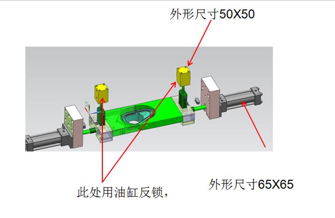
The customer had previously used a 40 mm bore rod cylinder, but the mold did not operate satisfactorily.
To solve the problem, an additional locking cylinder had been installed.
Unfortunately, the mold continued to experience the same operating issues.
At this point, the customer asked the Vega Technical Department to determine which locking cylinder should actually be used.
This situation is common in injection mold engineering.
Increasing cylinder size does not necessarily solve the underlying problem.
The entire application must first be analysed.
Engineering Begins with the Mold, Not the Catalogue
One of the most valuable lessons from this case is the methodology adopted by the Vega Technical Department.
Instead of immediately recommending a product code, Stefano Rogora first reviewed all the documentation previously received from the customer.
He carefully re-examined:
- the mold drawings;
- the PowerPoint presentation;
- the surfaces identified by the customer;
- the force calculations already available.
Only after verifying these engineering inputs did he begin calculating the forces acting on the locking system.
This demonstrates an important principle.
Professional hydraulic cylinder selection always starts with understanding the application—not with choosing a catalogue product.
The Surface Determines the Required Locking Force
Rather than using the bore diameter of the previous cylinder as a reference, the Vega Technical Department calculated the thrust force generated by the molten plastic.
For the first slide, the analysis considered:
- projected surface: 24.434 cm²;
- estimated cavity pressure: 350 bar;
- resulting thrust force: 8,551 kgf.
These calculations formed the basis for selecting the appropriate locking cylinder.
The process demonstrates that hydraulic cylinder sizing begins with the forces generated inside the mold rather than with the dimensions of the existing cylinder.
Plastic Pressure Changes Everything
The engineering analysis did not stop with a single operating condition.
The Vega Technical Department also evaluated a second design scenario by increasing the estimated plastic pressure to 500 bar.
Under these conditions, the calculated thrust force increased dramatically to 12,217 kgf, requiring a larger hydraulic cylinder.
Exactly the same methodology was repeated for the second slide.
The resulting thrust force increased from 8,715 kgf at 350 bar to 12,450 kgf at 500 bar.
This illustrates an essential engineering concept.
Changing only one design parameter—the assumed plastic pressure—can completely change the hydraulic cylinder selection.
Hydraulic Cylinder Selection Is Based on Calculated Forces
After completing the calculations, the Vega Technical Department recommended different hydraulic cylinders depending on the operating conditions.
For the estimated plastic pressure of 350 bar, the calculated forces indicated that the CF036 locking cylinder would be suitable.
When considering the more demanding condition of 500 bar, the recommended solution became the CF045.
This demonstrates that hydraulic cylinder selection is not based on habit or previous experience.
It is based on engineering calculations.
Engineering Means Verifying Assumptions
Another remarkable aspect of this case is that the engineers did not assume their first calculations were necessarily final.
They explicitly stated that if the customer remained concerned about cylinder dimensions or wanted a greater safety margin, an even larger CF056 cylinder could be considered.
Alternatively, they requested that the customer provide the force calculations based on the plastic pressure actually used in the mold.
This approach reflects professional engineering practice.
Rather than relying on assumptions, engineers verify the design conditions before making a final recommendation.
Good Engineering Does Not Rely on Previous Solutions
One of the strongest messages contained in this engineering case is that a previously installed hydraulic cylinder should never be considered proof that its size is correct.
The original 40 mm bore cylinder had already failed to solve the problem.
Adding another locking cylinder did not improve the mold’s behaviour either.
Instead of continuing to increase cylinder size by trial and error, the Vega Technical Department returned to the engineering fundamentals:
- analyse the mold;
- calculate the forces;
- verify the operating pressure;
- select the cylinder accordingly.
This systematic process reduces technical risk and leads to more reliable mold performance.
From Engineering Calculations to the Correct Hydraulic Cylinder Selection
In Part 1, we saw that selecting a locking hydraulic cylinder is not a matter of choosing the largest available bore.
The Vega Technical Department first analysed the mold geometry, reviewed the customer’s drawings, calculated the forces generated by the plastic pressure and only then identified the most suitable hydraulic cylinder.
This engineering methodology is essential because the locking system must safely resist the forces acting on the injection mold slide throughout the molding cycle.
Engineering Calculations Must Be Verified Every Time
One of the most interesting aspects of this case is that, several months after the initial analysis, the customer returned with additional questions regarding the locking cylinder.
Rather than relying on memory or on the previous recommendation, the Vega Technical Department replied that it was necessary to review the historical calculations before confirming the cylinder selection.
This reflects professional engineering practice.
Even when a similar project has already been analysed, engineers verify the calculations whenever:
- mold dimensions change;
- slide geometry is modified;
- operating conditions are updated;
- new technical information becomes available.
Good engineering is based on verified calculations—not on assumptions.
Slide Stroke Is as Important as Locking Force
Force is only one parameter in hydraulic cylinder selection.
The Vega Technical Department also verified the actual slide stroke before recommending the final solution.
Based on the information available, two different locking cylinder configurations were proposed.
For one configuration, the recommendation was:
- CF036M#070 + RF036211E
However, if the actual slide stroke was approximately 86 mm, a different solution became more appropriate:
- CF045M#090 + RF045211E.
This illustrates another important engineering principle.
The required stroke directly influences hydraulic cylinder selection.
Choosing a cylinder with sufficient force but an incorrect stroke can compromise the entire locking mechanism.
Plastic Pressure Determines Cylinder Size
The engineering calculations performed by the Vega Technical Department demonstrate how strongly hydraulic cylinder selection depends on the estimated cavity pressure.
Using a projected surface of 24.434 cm², the calculations produced:
- 8,551 kgf at 350 bar, leading to the recommendation of the CF036 locking cylinder;
- 12,217 kgf at 500 bar, requiring the larger CF045 cylinder.
The same approach was repeated for the second slide, producing comparable results:
- 8,715 kgf at 350 bar;
- 12,450 kgf at 500 bar.
These calculations demonstrate that cylinder selection depends on engineering data rather than previous experience.
Safety Margins Are Part of Good Engineering
Another valuable lesson from this case concerns engineering safety.
The Vega Technical Department did not limit its recommendations to a single hydraulic cylinder.
The engineers also explained that, if the customer wished to increase the safety margin or remained uncertain about the calculated conditions, a larger CF056 locking cylinder could also be considered.
Alternatively, they requested that the customer provide the force calculations corresponding to the actual plastic pressure used in production.
This approach demonstrates that hydraulic cylinder selection is rarely based on one fixed value.
Professional engineers evaluate multiple operating conditions before making the final decision.
Engineering Is More Than Choosing a Bore Diameter
One of the most common mistakes in mold design is believing that increasing cylinder diameter automatically solves locking problems.
This case demonstrates exactly the opposite.
Before recommending a hydraulic cylinder, engineers evaluate:
- projected plastic pressure area;
- injection pressure;
- resulting locking force;
- slide stroke;
- mold geometry;
- required safety margin.
Only after analysing all these parameters can the correct hydraulic cylinder be selected.
Simply replacing a 40 mm cylinder with a larger one without performing these calculations may increase costs without solving the underlying engineering problem.
A Structured Engineering Process Produces Better Results
The methodology followed by the Vega Technical Department illustrates a professional design process.
Instead of selecting a cylinder from the catalogue, the engineers:
- analysed the mold drawings;
- reviewed previous engineering documentation;
- calculated the projected forces generated by plastic pressure;
- evaluated different operating pressure scenarios;
- verified the required slide stroke;
- selected the appropriate locking cylinder;
- proposed alternative solutions where necessary.
This systematic approach reduces design errors, improves mold reliability and avoids unnecessary redesign work.
Conclusion
This real engineering case demonstrates that selecting a locking hydraulic cylinder requires much more than comparing bore diameters.
The Vega Technical Department first analysed the mold geometry, calculated the forces generated by different plastic pressures, verified the slide stroke and only then recommended the appropriate hydraulic cylinder. Depending on the calculated operating conditions, different solutions—including the CF036, CF045 and, where additional safety margins were required, the CF056—were considered.
This case reinforces one of the most important principles of injection mold engineering:
A locking hydraulic cylinder should never be selected by simply increasing its bore diameter. Correct selection requires engineering calculations based on plastic pressure, projected area, locking force, slide stroke and the real operating conditions of the mold.
Related Articles (Verified URLs on icvega.com)
- Locking Hydraulic Cylinders for Injection Molds
https://www.icvega.com/products/locking-hydraulic-cylinders - How to Find the Right Vega Cylinder or Accessory
https://www.icvega.com/choosing/find-right-vega-cylinder-accessory - Choosing the Right Cylinder: Pushing Force
https://www.icvega.com/choosing/choosing-the-right-cylinder-for-your-mold-pushing-force - Choosing the Right Cylinder: Stroke Selection
https://www.icvega.com/choosing/choosing-the-right-cylinder-for-your-mold-stroke - Hydraulic Cylinder Maintenance
https://www.icvega.com/maintenance/hydraulic-cylinder-maintenance
