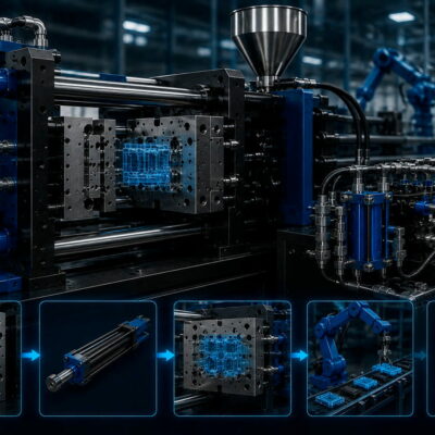
Selecting the correct hydraulic cylinder for an injection mold requires more than simply choosing a cylinder based on its physical dimensions.
When a cylinder is used to retract a core from a molded plastic component, the required force depends on the contact surface between the core and the plastic, the adhesion of the material and the geometry of the core.
A technical application analyzed by the Vega Team provides a useful example. The Customer needed to determine which hydraulic cylinder was sufficiently powerful to retract a tubular core from the molded plastic component.
The analysis considered two separate loads:
- the traction force required to pull the core out of the plastic;
- the thrust force generated by the plastic pressure acting on the frontal surface.
The two calculations produced very similar results, around 400 kgf, and led to the selection of a larger cylinder than the one initially considered by the Customer.
Why cylinder sizing must start from the application
A hydraulic cylinder should not be selected simply because its bore appears appropriate or because a similar mold previously used the same cylinder.
The first step is to understand what the cylinder actually has to move.
In this application, the Customer explained that the plastic component was a tube and asked the Vega Team to determine the correct cylinder size for retracting the core.
The Vega Team therefore analyzed the geometry of the core and calculated both the traction and thrust forces.
This approach is important because a core can experience different loads during different stages of the molding cycle.
1. Calculating the traction force
The first calculation considered the lateral surface of the core in contact with the plastic material.
The dimensions used in the calculation were:
- Core diameter: 13 mm
- Core length: 39.2 mm
- Plastic adhesion coefficient: 25 kg/cm²
- Draft angle: 0.5°
The diameter was converted from millimeters to centimeters:
13 mm = 1.3 cm
The core length was converted to:
39.2 mm = 3.92 cm
The lateral cylindrical surface was then calculated as:
1.3 × π × 3.92 ≈ 16 cm²
The Vega calculation therefore used approximately:
16 cm² of contact surface.
2. Applying the plastic adhesion coefficient
Once the contact surface had been determined, the Vega Team applied the assumed plastic adhesion value:
25 kg/cm²
The calculation was:
16 cm² × 25 kg/cm² = 400 kgf
The resulting estimated traction force was therefore approximately:
400 kgf
This is the force required to overcome the adhesion between the molded plastic and the lateral surface of the core according to the assumptions used in this application.
Why the draft angle matters
The original technical calculation explicitly refers to 0.5° of draft angle.
Draft is an important factor when a core has to be extracted from a molded component.
A core with insufficient draft can be more difficult to extract because the plastic can remain strongly engaged with the core surface.
However, the historical calculation provided in this application uses the 25 kg/cm² adhesion coefficient together with the stated geometry; it does not provide a separate numerical correction factor for the 0.5° draft angle.
For this reason, the approximately 400 kgf result should be understood as the result of the calculation documented by the Vega Team, rather than as a universal formula for every material and every draft angle.
3. Calculating the thrust force
The second calculation considered the frontal surface exposed to the pressure of the plastic inside the cavity.
The calculation used two diameters:
- outer diameter: 16.5 mm
- inner diameter: 13 mm
The resulting effective annular area was calculated as:
0.811 cm²
This is important because the plastic pressure does not act over the full outer circular area when there is an internal opening.
The effective area is therefore the difference between the outer and inner circular surfaces.
4. Applying the cavity pressure
The estimated plastic pressure in the cavity was:
500 bar
The Vega Team then calculated:
500 × 0.811 = 405.5 kgf
The resulting thrust force was approximately:
405.5 kgf
The two independent calculations therefore produced remarkably similar results:
| Load condition | Calculated force |
|---|---|
| Core traction / extraction | ≈ 400 kgf |
| Frontal thrust | ≈ 405.5 kgf |
These values were the basis for the cylinder selection.
Why both forces should be calculated
This application demonstrates an important principle in hydraulic-cylinder sizing.
It is not enough to calculate only the force required to retract the core.
The core can also be subjected to forces generated by the pressure of the plastic during injection.
Therefore, two different questions have to be answered:
How much force is required to extract the core?
and:
How much force is generated by the plastic pressure acting on the core?
The answers may be different.
In this particular application, however, they were very close: approximately 400 kgf for traction and 405.5 kgf for thrust.
The initial cylinder selection was too small
The Customer had initially considered a CE025 cylinder.
After performing the force calculations, the Vega Team concluded that the appropriate solution was instead:
- CE032, or
- CM032
with a minimum hydraulic working pressure of 100 bar.
This is a good example of why cylinder selection should be based on calculated application forces rather than simply choosing the smallest cylinder that appears compatible with the available space.
Why the working pressure matters
The hydraulic force generated by a cylinder depends on the effective piston area and the hydraulic pressure.
For a simplified pushing-force calculation:
F = P × A
where:
- F = hydraulic force;
- P = hydraulic pressure;
- A = effective piston area.
Once the required mechanical force has been calculated, the engineer can determine whether the selected cylinder can generate sufficient force at the available hydraulic pressure.
In this application, the Vega Team specifically identified the CE032 or CM032 at a minimum working pressure of 100 bar as suitable.
That is a much more meaningful selection criterion than simply saying that a certain cylinder “looks large enough.”
The importance of the available hydraulic pressure
The same cylinder can generate different forces depending on the pressure available from the hydraulic system.
This means that cylinder selection should consider both:
required mechanical force
and
available hydraulic pressure.
A cylinder that is suitable at one operating pressure may not provide sufficient force at a lower pressure.
For this reason, the Vega Team did not simply recommend the CE032 or CM032 as an isolated product. The recommendation was specifically associated with the minimum hydraulic working pressure of 100 bar.
The difference between theoretical force and application requirements
The calculations in this case should be understood as an engineering estimate based on the assumptions provided.
The traction calculation used:
- a 13 mm core diameter;
- a 39.2 mm contact length;
- 25 kg/cm² plastic adhesion;
- 0.5° draft.
The thrust calculation used:
- 16.5 mm outer diameter;
- 13 mm inner diameter;
- 500 bar estimated cavity pressure.
Changing any of these parameters can change the required cylinder size.
For example, a different plastic material or a different core length could significantly change the extraction force.
Likewise, a larger projected area or higher cavity pressure could increase the thrust force.
A useful design workflow
This technical case suggests a practical workflow for selecting a hydraulic cylinder for core retraction.
Step 1 – Identify the moving component
Determine exactly what the hydraulic cylinder has to retract.
In this case, it was a tubular core inside a molded plastic component.
Step 2 – Calculate the plastic contact surface
For a cylindrical core, the relevant lateral area can be calculated from:
π × diameter × contact length
The application produced approximately:
16 cm².
Step 3 – Estimate the extraction force
Apply the appropriate plastic adhesion coefficient.
The documented calculation used:
25 kg/cm²
and obtained:
approximately 400 kgf.
Step 4 – Calculate the frontal projected area
If the component is subjected to cavity pressure, calculate the effective frontal area.
The documented annular area was:
0.811 cm².
Step 5 – Calculate the pressure force
Using the estimated cavity pressure of:
500 bar
the calculated thrust force was:
approximately 405.5 kgf.
Step 6 – Compare the two loads
The cylinder must be selected according to the relevant worst-case operating condition.
In this case, the two calculated forces were almost identical.
Step 7 – Check the available hydraulic pressure
Finally, compare the required force with the force that the candidate cylinder can generate at the actual hydraulic pressure available.
The Vega Team’s conclusion was that CE032 or CM032 at a minimum working pressure of 100 bar was appropriate.
Why the smallest possible cylinder is not always the right choice
A smaller cylinder may appear attractive because it occupies less space and may cost less.
However, selecting a cylinder simply because it fits physically can create problems if the available force is insufficient.
An undersized cylinder may cause:
- incomplete core retraction;
- excessive operating pressure;
- unreliable mold operation;
- increased cycle interruptions;
- inability to overcome plastic adhesion;
- insufficient resistance during injection.
The technical case shows precisely why the Customer’s initial CE025 selection was reconsidered after the force calculation.
Why the largest cylinder is not automatically the best solution either
The opposite approach can also be problematic.
Choosing a cylinder substantially larger than necessary may result in:
- unnecessary space requirements;
- higher oil consumption;
- slower movement depending on the hydraulic circuit;
- higher component cost;
- unnecessary oversizing of the hydraulic system.
The goal is therefore not to select the largest cylinder available.
The goal is to select a cylinder whose characteristics are appropriate for the actual calculated load and operating pressure.
The calculation should be based on the actual mold geometry
The Customer originally asked the Vega Team for the calculations used to “find” the correct cylinder because the intention was to understand how to perform this type of evaluation.
This is an important point.
Cylinder sizing is much more reliable when it starts from the mold drawing.
The engineer can identify:
- core diameter;
- contact length;
- frontal area;
- draft angle;
- plastic contact conditions;
- cavity pressure;
- direction of movement;
- hydraulic pressure available.
Only after these parameters are established should the cylinder be selected.
A practical example of application-based sizing
The sequence in this case can be summarized as follows:
Core geometry
→ 13 mm diameter × 39.2 mm length
Contact surface
→ approximately 16 cm²
Plastic adhesion
→ 25 kg/cm²
Extraction force
→ approximately 400 kgf
Then:
Outer diameter
→ 16.5 mm
Inner diameter
→ 13 mm
Effective frontal area
→ approximately 0.811 cm²
Cavity pressure
→ 500 bar
Thrust force
→ approximately 405.5 kgf
Finally:
Cylinder selection
→ CE032 or CM032
Minimum hydraulic working pressure
→ 100 bar.
Connection with modern Vega cylinder selection
Vega’s current documentation confirms that its hydraulic cylinders for molds cover different applications and that cylinder configurations can be customized according to customer requirements. The official catalog organizes the products according to applications such as cart and plug movement, ejection plate movement, unscrewing and mechanical locking.
This reinforces the importance of selecting the cylinder according to the function it performs inside the mold, rather than treating every hydraulic cylinder as an interchangeable actuator.
Conclusion
Selecting the correct hydraulic cylinder for core retraction requires a calculation of the actual forces generated by the mold application.
In the documented application, the Vega Team calculated the extraction force from the lateral contact surface between the 13 mm diameter core and the plastic, using a 25 kg/cm² adhesion coefficient. The result was approximately 400 kgf.
A second calculation considered the 0.811 cm² effective frontal area and an estimated 500 bar cavity pressure, producing a thrust force of approximately 405.5 kgf.
Because the initially considered CE025 was not considered suitable, the Vega Team recommended a CE032 or CM032 cylinder, operating at a minimum hydraulic pressure of 100 bar.
The main lesson is simple:
The correct hydraulic cylinder should be selected from the forces generated by the actual mold geometry, not simply from the cylinder dimensions or the available installation space.
For core-retraction applications, both traction/extraction force and thrust force should be evaluated before the final cylinder is selected.
Useful and Verified URLs
- How to Calculate the Correct Hydraulic Cylinder Size for Injection Molds — Official Vega technical article explaining how core geometry, plastic adhesion, thrust and extraction forces affect cylinder selection.
- How to Calculate the Required Hydraulic Cylinder Force for an Injection Mold — Official Vega support article focused on calculating the force required from a hydraulic cylinder in an injection-mold application.
- Hydraulic Cylinders for Molds — Official Vega product category covering hydraulic cylinders for plastic injection molds and their different applications.
- Hydraulic Cylinders Catalog — Official Vega catalog page for the hydraulic-cylinder range, including the CE and CM families.
- Cart and Plug Movement Hydraulic Cylinders — Official Vega category for cylinders used to move carts, pins, plugs and other mold components that can create undercuts.