

A Real Engineering Case on Plastic Pressure, Adhesion Forces and Mechanical Locking
Selecting a self-locking hydraulic cylinder for an injection mold is far more complex than choosing a bore diameter and stroke from a catalog.
The cylinder must withstand the forces generated during every phase of the molding cycle while guaranteeing dimensional accuracy, preventing flash and ensuring safe operation even if hydraulic pressure is temporarily lost.
If the holding force is underestimated, the moving insert may open during injection, causing severe quality problems or even damaging the mold.
Conversely, an oversized cylinder increases costs, occupies valuable space inside the mold and unnecessarily complicates the design.
The correct engineering approach is therefore based on force calculations, not assumptions.
This real technical support case demonstrates how the Vega Technical Department analyzed the geometry of a mold insert, calculated both the injection force and the plastic adhesion force, and selected the most suitable self-locking hydraulic cylinder using objective engineering calculations.
The Customer’s Request
A mold manufacturer contacted Vega requesting a self-locking hydraulic cylinder for a license plate light mold.
The application required:
- one self-locking cylinder for each cavity slot;
- cylinder stroke of 10 mm;
- molded material PP-EPDM TV20 + UV.
To support the engineering evaluation, the customer supplied partial 3D CAD models in IGS and STEP format and requested confirmation that the proposed cylinder used a true mechanical locking system.
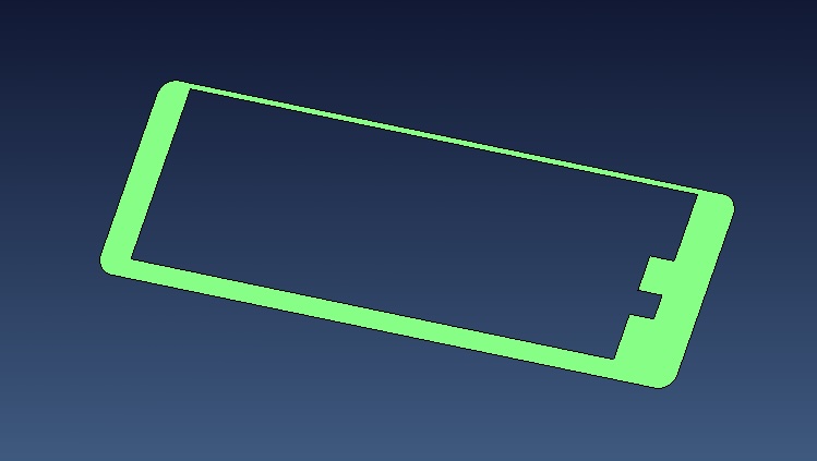
Engineering Always Starts from the Geometry
Rather than immediately selecting a cylinder, the Vega Technical Department first analyzed the geometry of the molded component.
Using the customer’s CAD model, engineers measured two different projected areas:
- frontal area exposed to cavity pressure;
- lateral area subjected to plastic adhesion during mold opening.
These two surfaces generate completely different mechanical loads and therefore require separate calculations.
Ignoring either one could result in an incorrect cylinder selection.
Calculating the Injection Holding Force
The first calculation evaluates the force generated by the molten plastic during injection.
The basic engineering equation is:
where
- F = Force
- P = Plastic cavity pressure
- A = Effective projected area
The engineering analysis determined:
Projected area
A = 9 cm²
Estimated cavity pressure
P = 500 bar
Since
1 bar ≈ 1.0197 kgf/cm²
the effective pressure becomes
500 × 1.0197 = 509.9 kgf/cm²
Therefore
Force = 509.9 × 9
Force = 4589 kgf
Rounded for engineering purposes:
≈ 4500 kgf
This value perfectly matches the calculation performed by the Vega Technical Department.
What Does 4,500 kgf Really Mean?
A force of 4,500 kgf corresponds to approximately:
- 44.1 kN
- the weight of a medium-sized SUV
- nearly 4.5 metric tons acting on a single mold insert.
This enormous force explains why relying only on hydraulic pressure is often insufficient for high-pressure injection molds.
Mechanical locking becomes essential to guarantee process stability.
Calculating the Plastic Adhesion Force
After cooling, the plastic adheres to the steel cavity surfaces.
When the mold opens, the insert must overcome this adhesion.
The calculation is based on:
where
- σ = plastic adhesion coefficient
- A = lateral contact area
Measured values:
Lateral area
9.14 cm²
Plastic adhesion coefficient
27 kg/cm²
Therefore
Force = 27 × 9.14
Force = 246.8 kgf
Rounded:
≈ 247 kgf
again confirming the engineering calculations performed during the project.
Comparing the Two Forces
One of the most interesting engineering observations is the enormous difference between the two calculated loads.
| Load | Value |
|---|---|
| Injection force | 4,589 kgf |
| Adhesion force | 247 kgf |
The injection force is therefore
4589 ÷ 247 = 18.6
times greater than the extraction force.
This means that the cylinder selection is governed almost entirely by the cavity pressure generated during injection.
The adhesion force remains an important verification but is not the critical sizing condition.
Why Mechanical Locking Is Essential
Suppose the hydraulic system suddenly loses pressure during the injection phase.
Without mechanical locking, the insert could immediately be subjected to nearly 4.5 tons of separating force.
Even a very small movement could produce:
- flash;
- dimensional defects;
- damaged slides;
- broken inserts;
- expensive mold repairs.
A self-locking hydraulic cylinder eliminates this risk because the locking force is maintained mechanically rather than hydraulically.
This considerably increases process safety and reliability.
Selecting the Appropriate Hydraulic Cylinder
After completing all calculations, the Vega Technical Department proposed two self-locking solutions.
Primary recommendation:
- 2 × CF030M010 + RF030211E
Alternative solution:
- 2 × CF030M010 + RF030271C
The engineering team also confirmed that complete 3D models would be supplied for integration into the customer’s mold design, while the commercial quotation would follow separately.
Engineering Decisions Must Be Based on Numbers
One of the strongest lessons from this case is the engineering methodology itself.
The cylinder was not selected because it “looked suitable.”
Instead, the engineers:
- analyzed the CAD geometry;
- measured the effective surfaces;
- calculated cavity pressure;
- calculated adhesion forces;
- evaluated each insert separately;
- selected the locking system according to actual mechanical loads.
This approach minimizes risk while avoiding unnecessary oversizing.
Lessons Learned from This Real Engineering Case
Selecting a self-locking hydraulic cylinder requires understanding the complete mechanical behavior of the mold.
Pressure generated during injection and adhesion forces generated during demolding act in different directions and with dramatically different magnitudes.
Only by calculating both conditions can engineers choose a locking system that guarantees safety, reliability and long service life.
The real value of engineering lies in transforming CAD geometry into measurable forces and then into a technically justified design solution.
Engineering Conclusions
This real technical support case demonstrates how hydraulic cylinder selection should always begin with engineering calculations rather than catalog dimensions.
The Vega Technical Department analyzed the customer’s CAD model, calculated a cavity pressure force of approximately 4,500 kgf and an extraction force of approximately 247 kgf for each mold insert, before proposing two suitable self-locking hydraulic cylinder solutions.
The calculations revealed that the injection force is almost 19 times greater than the adhesion force, confirming that cavity pressure is the governing design condition for the locking system.
The most important lesson is simple:
Reliable mold design is built on engineering calculations—not assumptions. Every self-locking hydraulic cylinder should be selected according to the actual forces generated inside the mold, ensuring maximum safety, precision and long-term reliability.
