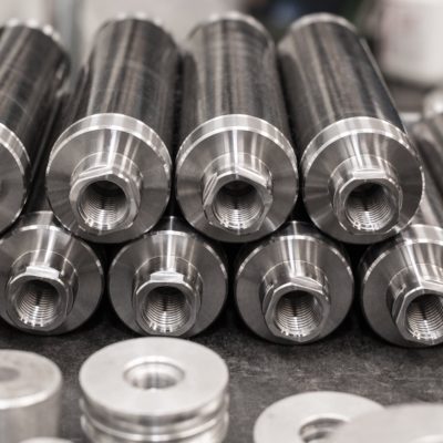
A self-locking hydraulic cylinder is designed to provide both hydraulic movement and mechanical locking. In injection mold applications, however, reliable operation depends not only on the cylinder itself but also on the hydraulic circuit connected to it.
A technical support case involving a V260CF self-locking hydraulic cylinder illustrates this point clearly. The Cliente reported that the cylinder initially reached the required return position and the corresponding signal was detected correctly. After approximately 5–10 seconds, however, the return signal disappeared. The cylinder appeared to move slightly after reaching its position.
The hydraulic connection between the V260CF and the check valve included a flexible hose, and the Cliente specifically asked whether residual pressure inside the hose could be sufficient to move the piston.
The Vega Team did not immediately attribute the problem to a single component. Instead, several possible causes were identified and a systematic troubleshooting approach was proposed.
The Problem: The Cylinder Reaches Position, Then Moves
The reported sequence was particularly significant.
The operator applied pressure to retract the cylinder. The cylinder moved correctly and the expected signal was initially present.
Then, after approximately 5–10 seconds:
- the return signal disappeared;
- the cylinder appeared to move slightly;
- the problem occurred after the cylinder had initially reached the expected position.
This type of delayed movement is different from a cylinder that simply cannot reach its end position.
The fact that the cylinder initially reached the position suggested that the investigation should consider what happened after the hydraulic movement had apparently been completed.
That led the Vega Team to examine not only the mechanical locking cylinder, but the complete hydraulic circuit.
Four Possible Causes Identified by the Vega Team
In the technical response, the Vega Team identified four possible causes:
- A flexible tube between the cylinder and the valve
- Air inside the hydraulic circuit
- Oil leakage through the cylinder piston seals
- Internal oil leakage inside the pump valve
This is an important diagnostic approach.
Rather than assuming that the V260CF itself was defective, the investigation considered the complete chain:
Valve → hydraulic connection → oil → cylinder → piston → locking mechanism → end-position signal
A problem anywhere along this chain can potentially influence the final position of the cylinder.
Why the Flexible Hose Was Investigated
The Cliente had a flexible hose installed between the V260CF and the check valve.
The question was whether pressure remaining in the hose could cause enough movement to change the cylinder position after the operator had already completed the hydraulic movement.
The Vega Team’s recommendation was straightforward:
Use a rigid connection between the cylinder and the valve.
This was the first corrective action suggested, together with bleeding the air from the hydraulic circuit.
It is important to distinguish between a suspected cause and a confirmed root cause.
The documentation does not confirm that the flexible hose was ultimately proven to be the cause of the movement. It records the hose as one of the possible causes and documents the recommended diagnostic action.
That distinction is important when analysing a real engineering case.
Why Hydraulic Circuit Design Matters
A hydraulic cylinder cannot be considered independently from the circuit supplying it.
Vega’s current technical documentation similarly emphasizes that hydraulic-cylinder accessories include check valves, flow regulators and hydraulic connections intended to ensure that the cylinder receives and retains the required oil flow and pressure.
For self-locking applications, this becomes particularly important because the cylinder combines two different functions:
- hydraulic actuation;
- mechanical locking.
The official Vega V260CF documentation identifies the product as a self-locking rod hydraulic cylinder with integrated end-stroke switches.
Therefore, an unexpected change in the end position can involve both the hydraulic circuit and the mechanical locking system.
Air in the Hydraulic Circuit
The second possible cause identified by the Vega Team was air inside the oil circuit.
This is especially relevant when precise positioning is required.
Air is significantly more compressible than hydraulic oil. If air remains trapped in the circuit, the hydraulic system can behave less rigidly and may produce changes in position as pressure conditions change.
The Vega Technical documentation available in the Library also emphasizes the importance of properly bleeding hydraulic circuits. A previous Vega technical case involving a V260 locking cylinder specifically recommended bleeding the hydraulic circuit before production.
The broader engineering principle is therefore clear:
Before investigating a sophisticated locking-cylinder problem, make sure that the hydraulic circuit has been correctly filled and completely bled.
Why Air Can Be Particularly Important in a Self-Locking Application
A conventional hydraulic cylinder can sometimes tolerate small changes in hydraulic behaviour without producing an obvious positioning problem.
A self-locking cylinder used in a mold can be more sensitive because the cylinder may need to reach a specific mechanical position for the locking mechanism and end-of-stroke system to function correctly.
Vega’s technical information explains that the V260CF locks the rod in its extended end-of-stroke position.
The official V260CF technical documentation also distinguishes between:
- static locking force;
- thrust force;
- traction force;
- locking force with and without preload.
This demonstrates that the V260CF is not simply a conventional actuator. Its hydraulic movement and mechanical locking functions must be considered together.
Possible Internal Leakage Through the Piston Seals
The third possibility identified by the Vega Team was oil leakage through the piston seals inside the cylinder.
If oil can pass internally across the piston, the cylinder may not maintain its position as expected.
This is another reason why replacing the cylinder immediately should not necessarily be the first step.
Before dismantling the cylinder, the hydraulic circuit should be checked systematically.
A useful diagnostic sequence is:
Hydraulic connection → air → valve → cylinder
This makes it possible to determine whether the problem originates externally or internally.
Possible Leakage Inside the Pump Valve
The fourth possible cause identified in the case was oil leakage inside the pump valve.
This is an important reminder that a cylinder can appear to be losing position even when the cylinder itself is functioning correctly.
If the control valve does not properly maintain the required hydraulic condition, pressure may change over time and the cylinder can respond accordingly.
For this reason, troubleshooting should not stop at the cylinder’s hydraulic ports.
The valve and the rest of the circuit must also be evaluated.
The Recommended First Step: Rigid Connection and Air Bleeding
The Vega Team’s first recommendation was deliberately simple:
Use a rigid connection between the cylinder and the valve and bleed the air from the circuit.
This is a useful troubleshooting philosophy.
Before replacing a cylinder or modifying the mold, eliminate the simplest variables that can affect positioning.
In this case, the first intervention addresses two of the main concerns simultaneously:
1. Replace the flexible section
A rigid connection removes the flexible hose from the diagnostic equation.
2. Bleed the hydraulic circuit
Removing trapped air reduces hydraulic compressibility and eliminates another possible source of delayed movement.
If the problem disappears after these changes, the investigation has a much clearer direction.
If the problem remains, the next steps can focus more closely on the cylinder seals and valve.
The Role of the Check Valve
The case specifically shows a check valve installed between the hydraulic circuit and the V260CF.
Check valves are an important component in hydraulic-cylinder applications because they can help retain hydraulic pressure and prevent unwanted oil flow in the reverse direction.
Vega currently offers controlled check valves among its hydraulic-cylinder accessories, alongside rod accessories, flow regulators and hydraulic connections.
For self-locking mold applications, the hydraulic circuit remains important even though the cylinder incorporates a mechanical locking mechanism.
Vega’s current technical guidance explains that the V260 self-locking system achieves maximum performance when the required hydraulic pressure is maintained during the injection phase, and that a check valve can be used when the machine cannot maintain that pressure continuously.
This reinforces an important concept:
Mechanical locking and hydraulic circuit performance should be considered as parts of the same system.
The V260CF: Mechanical Locking Plus Hydraulic Actuation
The V260CF technical documentation provides separate performance data for locking, thrust and traction. For example, the catalogue lists different static locking forces according to bore size and preload condition.
This distinction is fundamental.
The hydraulic pressure is primarily responsible for moving the piston and rod.
The mechanical locking system provides the high static holding capacity associated with the self-locking function.
Therefore, a positioning problem should not automatically be interpreted as a failure of the mechanical locking system.
The hydraulic circuit can still influence whether the cylinder reaches and maintains the correct position.
Full Stroke and End-Position Detection
Another important aspect of V260CF operation is reaching the correct end position.
Vega’s technical documentation explains that the self-locking mechanism is designed to engage when the rod reaches its appropriate end-of-stroke position.
This means that a few millimetres of unexpected movement can be important.
In the documented case, the Cliente observed that the cylinder initially reached the required position and then appeared to move slightly, causing the return signal to disappear.
This is precisely why the end-position signal should not be considered merely an electrical issue.
If the cylinder mechanically changes position, the sensor can simply be reporting that mechanical change.
The correct diagnostic question is therefore:
Why did the cylinder position change?
rather than simply:
Why did the sensor signal disappear?
A Systematic Troubleshooting Procedure
Based on the documented case and the supporting Vega technical information, a logical troubleshooting sequence is:
Step 1 — Confirm the symptom
Verify that the cylinder initially reaches the expected position and that the signal is correctly detected.
Step 2 — Check the hydraulic connection
Inspect the connection between the valve and V260CF.
If a flexible hose is used, consider replacing it temporarily with a rigid connection as recommended by the Vega Team.
Step 3 — Bleed the hydraulic circuit
Remove trapped air before evaluating the stability of the cylinder position.
Step 4 — Check the valve
Verify whether the valve can maintain the required hydraulic condition and whether there is evidence of internal leakage.
Step 5 — Check the cylinder
If the hydraulic circuit is functioning correctly, investigate possible internal leakage through the piston seals.
Step 6 — Check the mechanical position
Confirm that the cylinder actually reaches the required end position and that the mechanical installation does not prevent correct locking.
Step 7 — Check the sensor
Only after the mechanical and hydraulic conditions have been verified should the sensor itself become the primary suspect.
This sequence avoids replacing electrical or hydraulic components before the real source of the movement has been identified.
What This Case Does—and Does Not—Prove
The most important conclusion from this technical case is that the documentation does not establish a definitive root cause.
The Cliente suspected that residual pressure in the flexible hose might be causing the piston to move.
The Vega Team identified four possible causes:
- flexible hose;
- air in the circuit;
- piston-seal leakage;
- valve leakage.
The recommended first action was to use a rigid connection and bleed the circuit.
The available documentation does not contain a subsequent message confirming which of these possibilities was ultimately responsible.
Therefore, the correct engineering conclusion is not that “the flexible hose caused the failure.”
The documented conclusion is that the flexible hose and hydraulic circuit were considered possible contributors and that a rigid connection plus air bleeding was recommended as the first diagnostic intervention.
Conclusion
A self-locking hydraulic cylinder should always be evaluated as part of the complete hydraulic and mechanical system.
In this case, a V260CF initially reached its required position and generated the correct signal, but after approximately 5–10 seconds the signal disappeared and the cylinder appeared to move slightly.
The Vega Team identified four possible causes: the flexible hydraulic connection, air in the circuit, internal leakage through the piston seals and leakage inside the pump valve.
The first recommended action was to replace the flexible connection with a rigid connection and perform a complete air bleed of the hydraulic circuit.
The V260CF documentation confirms that this is a mechanical self-locking cylinder with integrated end-stroke switches and separate locking, thrust and traction characteristics.
The broader lesson for mold designers and hydraulic engineers is straightforward:
When a self-locking cylinder appears to lose position, do not investigate the cylinder alone. Check the complete hydraulic circuit, the connection between the valve and cylinder, trapped air, valve leakage, cylinder leakage and the actual mechanical end position.
That systematic approach can prevent unnecessary component replacement and make it much easier to identify the real source of an intermittent positioning problem.
Useful and Verified Vega URLs
- Vega Self-Locking Hydraulic Cylinders — Overview of Vega’s mechanical self-locking hydraulic-cylinder technology.
- Vega Hydraulic Cylinder Accessories — Rod accessories, check valves and flow regulators.
- Vega VR Hydraulic Cylinder Accessories — Hydraulic connections, check valves and accessories for cylinder installation.
- Why Hydraulic Self-Locking Cylinders Move During Injection — Technical explanation of locking force, hydraulic pressure and circuit stability.
- Why Servo Hydraulic Machines Need Pilot-Operated Check Valves — Relevant Vega engineering discussion about check valves, pressure retention and air bleeding.
- How to Select the Correct Self-Locking Hydraulic Cylinder for an Injection Mold — Cylinder selection, locking function and correct end position.