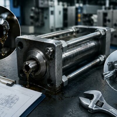
In injection mold engineering, a dimensional difference that appears extremely small can have a significant effect on the operation of a self-locking hydraulic cylinder.
A technical case illustrates this very clearly.
A Customer received four locking cylinders. Three of the fixing flanges measured 32 mm in thickness, while one measured only 31.27 mm. The Customer requested a replacement flange with the same 32 mm thickness as the other three.
At first sight, the difference may appear negligible:
32.00 mm − 31.27 mm = 0.73 mm
However, according to the Vega Team’s technical assessment, this difference was sufficient to create an incorrect cylinder position with excessive preload when the flange was a neutral, non-adjustable version.
This case demonstrates an important principle in injection mold engineering:
When a self-locking hydraulic cylinder uses preload, flange dimensions are functional dimensions—not simply manufacturing dimensions.
Why 0.73 mm Can Be Important
A difference of 0.73 mm might seem insignificant when considering the overall dimensions of a mold or hydraulic cylinder.
For a preload system, however, the relevant dimensions can be measured in tenths or even hundredths of a millimeter.
Vega’s technical documentation explains that preload is used to compensate for the elastic deformation of the cylinder rod and the components connected to it. The purpose is to establish controlled compression before injection so that the mold component remains correctly positioned when injection forces are applied.
Therefore, a flange that is 0.73 mm thinner than specified does not simply represent a small dimensional variation.
It can change the entire mechanical position of the cylinder.
What Is Preload in a Self-Locking Hydraulic Cylinder?
Preload is a controlled mechanical compression introduced into the cylinder system before the injection phase.
During injection, the cylinder rod and the connected mold components are subjected to forces and undergo a certain amount of elastic deformation.
Without compensation, this deformation can allow the plug, core or other mold component to move slightly.
The basic principle can be represented as:
Without preload:
Injection force → elastic deformation → component movement → possible flash
With preload:
Pre-compression → compensation of elastic deformation → more stable component position
Vega’s technical documentation specifically explains that the preload values take into account the elasticity and compression of the cylinder rod, while the elasticity of the slide, core or other component connected to the rod must also be considered.
This is why the flange becomes an important part of the engineering calculation.
The Difference Between a Neutral Flange and an Adjustable Flange
The technical case makes an important distinction.
The flange involved in the complaint was a neutral flange.
According to the Vega Team, because it was a neutral flange, the 0.73 mm dimensional difference would result in an incorrect cylinder position and excessive preload.
With a neutral flange, there is no convenient adjustment mechanism that allows the cylinder position to be fine-tuned after installation.
This means that the flange’s manufactured thickness directly influences the installed position of the cylinder.
By contrast, Vega’s technical documentation describes the RF…211E adjustable preload flange as a practical solution for applications where preload needs to be adjusted during mold installation or testing.
This difference is fundamental:
| Neutral flange | Adjustable flange |
|---|---|
| Fixed geometry | Adjustable geometry |
| Flange dimension directly determines position | Cylinder position can be fine-tuned |
| Dimensional error can directly affect preload | Small dimensional variations can be compensated |
| Less flexible during mold trials | More practical during mold commissioning |
Why Excessive Preload Is Not Always Better
It is tempting to assume that more preload will always improve the performance of a self-locking cylinder.
That is not the case.
Vega’s technical instructions explicitly warn that excessive preload can interfere with the correct locking function and can also compromise proper unlocking.
This is a critical point.
The objective is not to maximize preload.
The objective is to apply the correct preload for the specific cylinder and mold application.
An excessive preload can therefore create a new problem while attempting to solve another one.
Preload Values Can Be Very Small
The Vega technical instructions provide maximum preload values according to cylinder bore and stroke.
For example, the documentation gives values such as:
- Ø36 mm bore, 35 mm stroke → 0.10 mm maximum preload
- Ø36 mm bore, 70 mm stroke → 0.13 mm
- Ø36 mm bore, 100 mm stroke → 0.15 mm
- Ø36 mm bore, 120 mm stroke → 0.17 mm
Other configurations in the table also remain within a few tenths of a millimeter.
This provides important context for the 0.73 mm dimensional difference in the Customer’s flange.
The difference between the correct and incorrect flange thickness was several times larger than the preload values typically being adjusted.
That explains why the Vega Team considered the difference mechanically significant.
How an Adjustable Flange Works
Vega’s technical instructions describe a specific procedure for the RF…211E adjustable flange.
The process begins by establishing a 1 mm reference distance between the flange and the perpendicular plane of the cartridge.
The cylinder is then positioned so that the mold component reaches its correct mechanical zero position.
Vega recommends checking the contact between the plug or core and the die, including the use of blue Prussian Blue test paste as a mechanical contact check.
Only after this reference position has been established is the preload adjusted.
For example, if the required preload is 0.15 mm, the Vega procedure uses:
1.00 mm − 0.15 mm = 0.85 mm
An appropriate 0.85 mm flat shim is then used during the adjustment procedure.
This illustrates just how precisely the mechanical installation has to be controlled.
Why the Mold’s Mechanical “Zero” Matters
Preload should not be adjusted simply by rotating the cylinder until the mold appears to close correctly.
Vega recommends establishing a defined mechanical reference, or point “0”, before applying the preload.
The sequence is therefore:
Correct mold position
↓
Plug/core completely closed
↓
Mechanical point “0”
↓
Preload adjustment
↓
Molding trials
This approach prevents preload from being used to compensate for an unrelated dimensional error in the mold.
If the mold itself is incorrectly dimensioned, simply adding preload may mask the real problem.
Why the Flange Must Be Checked Before Shipment
The Vega Team’s conclusion in this case was straightforward.
Because the Customer had received a neutral flange that was 0.73 mm thinner than the other flanges, the replacement flange should be supplied with the correct thickness.
The Vega Team also specifically stated that the flange to be shipped should be checked beforehand to prevent the same error from happening again.
This is a useful quality-control lesson.
When a component directly determines the position of a self-locking cylinder, dimensional inspection should not be treated as an administrative formality.
The dimension is part of the cylinder’s functional installation.
When an Adjustable Flange Is the Better Solution
Vega’s technical documentation recommends the adjustable RF…211E flange as a practical solution when preload needs to be established during mold testing.
One advantage is that the preload can be adjusted with the mold installed in the press, provided that the cylinder is accessible and there is sufficient space for the operator to perform the adjustment.
This can be particularly valuable during commissioning because the actual mold behavior may need to be evaluated before the final preload is established.
However, the adjustment also rotates the cylinder relative to its original design position.
This can change the orientation of:
- hydraulic ports;
- hydraulic connections;
- sensors;
- sensor cables.
Therefore, the mold design must provide enough space for the adjustment and for the resulting component positions.
What Happens With a Non-Adjustable Flange?
Vega’s technical instructions explain that when a non-adjustable flange is used, establishing preload may require machining the flange or, alternatively, using a shim between the accessory and the rod end, although this alternative is not recommended as the preferred solution.
This is less flexible than an adjustable flange.
It can also be difficult to perform during mold testing because the correct preload may only become apparent once the mold has been assembled and tested.
For this reason, the choice of flange should be considered during the mold design phase.
Preload and Injection Mold Quality
The purpose of preload is ultimately connected to the quality of the molded component.
During injection, pressure acts on the mold components.
Even small elastic deformations or clearances can allow a plug, core or slide to move.
This can contribute to:
- flash;
- material seepage;
- dimensional variation;
- imperfect shut-off;
- inconsistent production quality.
Vega’s current technical explanation of preload specifically describes the relationship between controlled pre-compression, elastic deformation and mold quality.
The company’s self-locking-cylinder technology also explains that the pre-loading flange is intended to compress the rod and connected components during setup so that the mold component can better resist injection pressure.
Preload Must Be Combined With Correct Hydraulic Conditions
Mechanical preload does not replace correct hydraulic operation.
Vega’s technical instructions specify that, for correct operation of the mechanical locking system, 120 bar push pressure should be maintained throughout the injection phase. If this cannot be maintained, the instructions call for a pilot-operated check valve to be installed directly on the cylinder using a nipple or another rigid fitting.
The same instructions explicitly state:
Do not use hoses to connect the valve to the cylinder.
The cylinder and valve should also be purged to remove possible air bubbles trapped in the hydraulic circuit.
This reinforces the idea that the flange, mechanical preload and hydraulic circuit cannot be considered independently.
A Small Dimensional Error Can Become a Functional Error
The most important lesson from this technical case is that a dimensional deviation should always be evaluated in relation to the function of the component.
A difference of:
0.73 mm
may be insignificant for some mechanical components.
For a flange that defines the position and preload of a self-locking hydraulic cylinder, it can be highly significant.
The Vega Team’s assessment was therefore not simply that one flange was “slightly thinner.”
The issue was that the dimensional difference could change the installed position of the cylinder and produce excessive preload.
That is a very different engineering problem.
The Importance of Dimensional Quality Control
This case also highlights a broader principle for manufacturers of hydraulic-cylinder assemblies and mold components.
Critical dimensions should be controlled according to their functional purpose, not simply according to whether they appear visually or geometrically reasonable.
For a self-locking cylinder installation, relevant dimensions may include:
- flange thickness;
- cylinder position;
- rod position;
- mold reference position;
- preload;
- connection geometry;
- mechanical contact surfaces.
An error in one dimension can propagate through the entire mechanical chain.
A Practical Engineering Checklist
When installing a self-locking hydraulic cylinder with a fixing flange, it is useful to verify:
Before installation
- Confirm the correct flange type.
- Confirm whether the flange is neutral or adjustable.
- Check the flange dimensions.
- Confirm the cylinder bore and stroke.
- Determine the permissible preload.
- Verify the mold’s mechanical reference position.
During installation
- Establish the correct point “0”.
- Verify contact between the moving component and the die.
- Apply the specified preload.
- Check the cylinder position.
- Verify that hydraulic ports and sensors remain accessible.
During mold testing
- Check for flash or material seepage.
- Verify locking and unlocking.
- Evaluate whether the preload is excessive or insufficient.
- Adjust only within the specified limits.
- Recheck the mechanical position after adjustment.
Before production
- Verify the final flange and cylinder position.
- Check the hydraulic circuit.
- Confirm the required pressure.
- Purge trapped air.
- Verify the complete system under actual operating conditions.
Conclusion
This technical case demonstrates why precision matters when installing self-locking hydraulic cylinders in injection molds.
A Customer received four locking cylinders, with three flanges measuring 32 mm and one measuring 31.27 mm. The 0.73 mm difference was considered significant because the flange was a neutral type: according to the Vega Team, the dimensional difference would produce an incorrect cylinder position with excessive preload.
Vega’s technical documentation shows why such a small dimensional difference can matter. Preload values themselves may be only a few tenths of a millimeter, and excessive preload can interfere with correct locking and unlocking.
For applications requiring adjustment, Vega recommends an RF…211E adjustable preload flange, which allows the cylinder position and preload to be fine-tuned during mold installation and testing.
The key engineering lesson is simple:
A flange is not just a mounting component when it determines the position and preload of a self-locking hydraulic cylinder. Its dimensional accuracy directly affects the mechanical behavior of the mold.
Useful and Verified Vega URLs
- Preload in Self-Locking Hydraulic Cylinders — Vega technical article explaining elastic deformation, preload, the RF211E adjustable flange and the relationship between preload and mold quality.
- How to Set the Preload on a Vega V270CG Self-Locking Hydraulic Cylinder — Detailed Vega procedure for setting preload with the RF…211E adjustable flange.
- Self-Locking Hydraulic Cylinders — Official Vega overview of mechanical locking and the pre-loading flange.
- VR Hydraulic Cylinders Accessories — Official Vega page covering cylinder mounting accessories, check valves, hydraulic connections and sensor testing.
- How to Size a Mechanical Self-Locking Hydraulic Cylinder for an Injection Mold — Useful engineering guidance on cylinder sizing, locking force and the effect of preload.