In the injection molding industry, hydraulic cylinder failures are often treated as maintenance issues.
A cylinder is removed from the mold, repaired, reinstalled, and production resumes.
But what happens when the same cylinder fails again?
And then fails once more in exactly the same way?
This was the challenge faced by Vega Technical Dep. when supporting a mold maker that we will identify only as H.T..
What initially appeared to be a routine cylinder repair became a complete engineering investigation involving mold design, hydraulic loads, injection pressure forces, dynamic stresses, and application sizing.
The outcome demonstrates why solving the root cause is far more valuable than simply repairing the symptom.
A Repeated Failure That Raised Questions
The customer contacted Vega regarding two self-locking hydraulic cylinders that had already undergone repair and had subsequently failed again.
The damage pattern was remarkably similar to the previous failure.
For experienced engineers, this is an important warning sign.
When a component repeatedly fails in the same manner, there is usually an underlying application issue rather than a product issue.
Instead of immediately proceeding with another repair, Vega Technical Dep. decided to investigate the entire system.
The objective was simple:
Determine why the cylinders continued to fail.
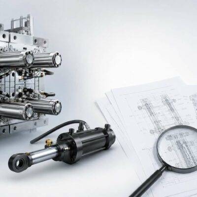
Looking Beyond the Damaged Components
Rather than focusing exclusively on the damaged cylinders, Vega engineers requested additional information, including:
- Hydraulic operating pressure
- Mold installation details
- 3D mold assembly data
- Side-action geometry
- Operating conditions
This approach reflects a fundamental engineering principle.
A hydraulic cylinder can only be evaluated correctly when the forces acting on it are fully understood.
As highlighted in modern mold engineering practice, successful mold design requires understanding statics, dynamics, material behavior, stress transmission, and the interaction between the molded plastic and the moving mold components.
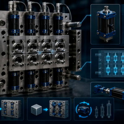
The 3D Analysis Revealed the Real Problem
After reviewing the mold assembly and the moving side-action mechanism, Vega engineers calculated the actual loads generated during injection.
The first step was determining the projected area exposed to cavity pressure.
The analysis revealed:
- Projected surface area approximately 39.4 cm²
- Estimated cavity pressure approximately 550 bar
The resulting force acting directly on the side core exceeded:
21,600 kgf
This value alone was significantly higher than many engineers would initially expect.
However, the investigation did not stop there.
Because the side-action moved at an angle of approximately 40 degrees, the actual force transmitted to the self-locking cylinder had to be calculated through the mechanism geometry.
The resulting load acting on the cylinder was approximately:
16,600 kgf
This was the critical discovery.
Why the Cylinders Continued to Fail
The calculations demonstrated that the installed self-locking cylinders were operating beyond their intended design limits.
This explains why repairing the cylinders did not solve the problem.
Each repair restored the cylinders to their original condition.
However, the operating conditions that caused the damage remained unchanged.
As soon as production resumed, the cylinders were again exposed to forces exceeding their safe operating range.
The failures were therefore not random.
They were predictable.
And they would continue to occur until the application itself was corrected.
Understanding Injection Pressure Forces
One of the most common mistakes in mold design is underestimating the effect of cavity pressure on moving mold components.
During injection, molten plastic behaves like a hydraulic medium.
Every square millimeter exposed to cavity pressure generates force.
When projected areas become large, the resulting loads can quickly reach several tons.
For this reason, Vega’s cylinder sizing procedures always consider:
- Injection pressure force
- Stripping force
- Ejection force
- Static holding force
These parameters are fundamental for selecting the correct hydraulic cylinder and avoiding overload conditions.
Ignoring them may lead to premature failures, reduced reliability, and repeated maintenance interventions.
The Hidden Factor: Dynamic Loads
The investigation uncovered another important aspect.
The side-action assembly had considerable mass and operated in a vertical position.
Under these conditions, static calculations alone are not sufficient.
A moving mass generates kinetic energy.
When motion stops abruptly at the end of the stroke, that energy must be dissipated somewhere.
If it is not controlled properly, it becomes a pressure spike and a mechanical shock load.
The Vega Technical Manual specifically warns that kinetic energy generated by high-speed movement or large moving masses must be absorbed through cushioning systems or external shock absorption devices.
Allowing this energy to be discharged directly against the cylinder end-of-stroke surfaces can cause severe damage and drastically reduce service life.
This meant that the application was likely suffering from two separate issues:
- Insufficient cylinder capacity.
- Excessive dynamic loading caused by the moving mass.
The combination created a highly demanding operating environment.
The Engineering Solution
Once the root cause had been identified, Vega Technical Dep. developed a corrective strategy.
The solution was not simply to repair the damaged cylinders again.
Instead, Vega recommended:
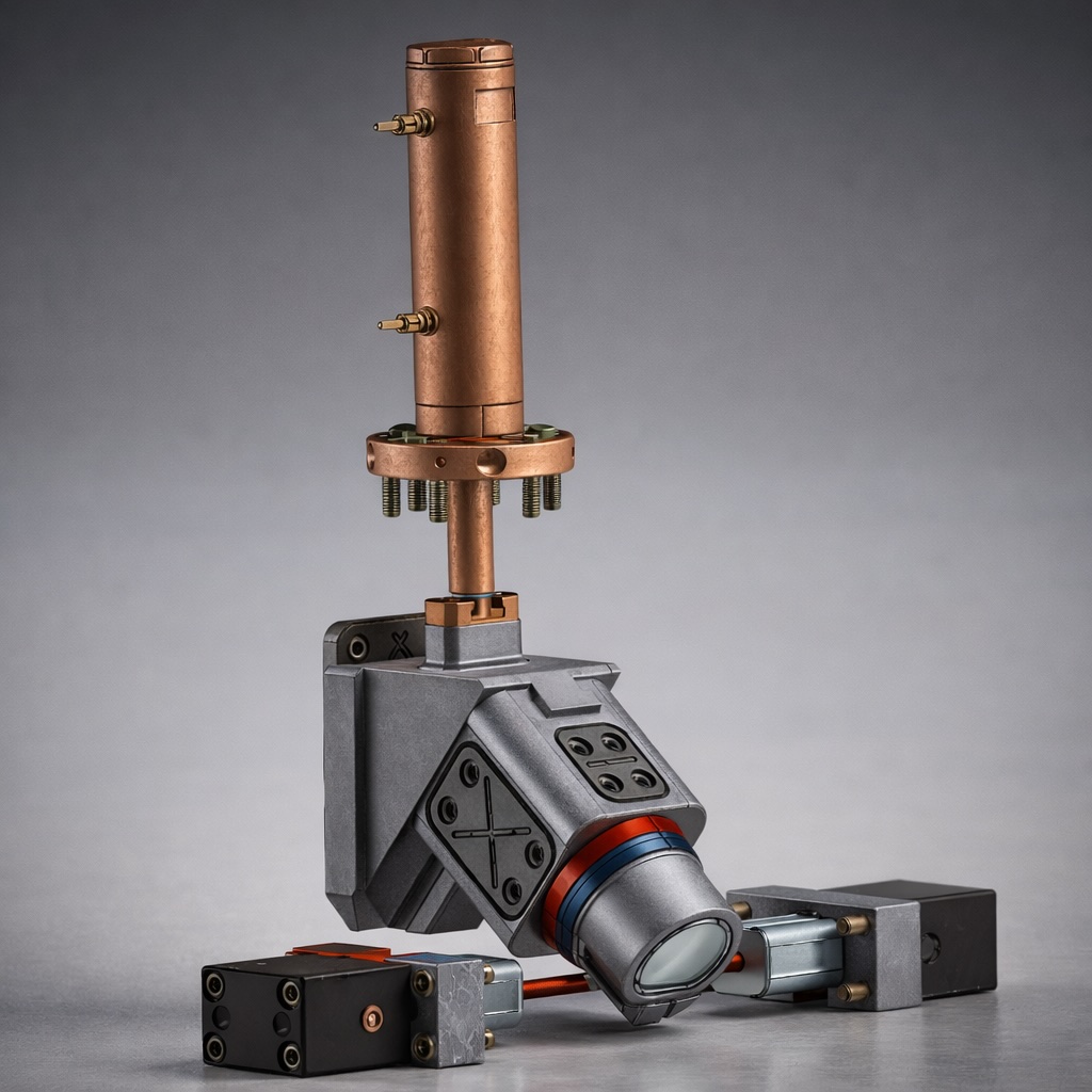
Larger Self-Locking Cylinders
The new cylinders were selected to withstand the actual forces generated by the mold with an appropriate safety margin.
Flow Regulation
Flow regulators were recommended to reduce operating speed and minimize impact forces during movement.
Dynamic Load Reduction
By controlling acceleration and deceleration, the kinetic energy generated by the moving side-action could be significantly reduced.
Long-Term Reliability
The objective was not merely restoring production.
The objective was preventing the same failure from occurring again.
Lessons Learned
This case highlights several important engineering principles.
1. Repeated failures are rarely coincidental
When the same damage appears repeatedly, the application should be investigated before repairing the component again.
2. Injection pressure creates enormous forces
Even relatively small projected areas can generate loads measured in tons.
3. Static calculations are not enough
Moving masses create dynamic loads that can exceed the static force calculations.
4. Repairs do not remove root causes
A repaired component will fail again if the operating conditions remain unchanged.
5. Engineering support creates value
The fastest solution is often replacing a component.
The best solution is understanding why it failed.
Conclusion
At Vega, technical support goes far beyond cylinder repair.
Every failure is treated as an opportunity to understand the application, verify the calculations, and identify the true cause of the problem.
In this case, the damaged cylinders were not the root cause.
They were simply the first visible sign of an overloaded system.
Through force calculations, 3D analysis, hydraulic engineering, and mold design expertise, Vega Technical Dep. identified the actual source of the problem and proposed a solution designed for long-term reliability.
Because in engineering, repairing the cylinder is easy.
Understanding why it failed is what prevents the next failure.